wheel bolts NISSAN LATIO 2008 Service User Guide
[x] Cancel search | Manufacturer: NISSAN, Model Year: 2008, Model line: LATIO, Model: NISSAN LATIO 2008Pages: 2771, PDF Size: 60.61 MB
Page 1687 of 2771
EM-10
< SERVICE INFORMATION >
PREPARATION
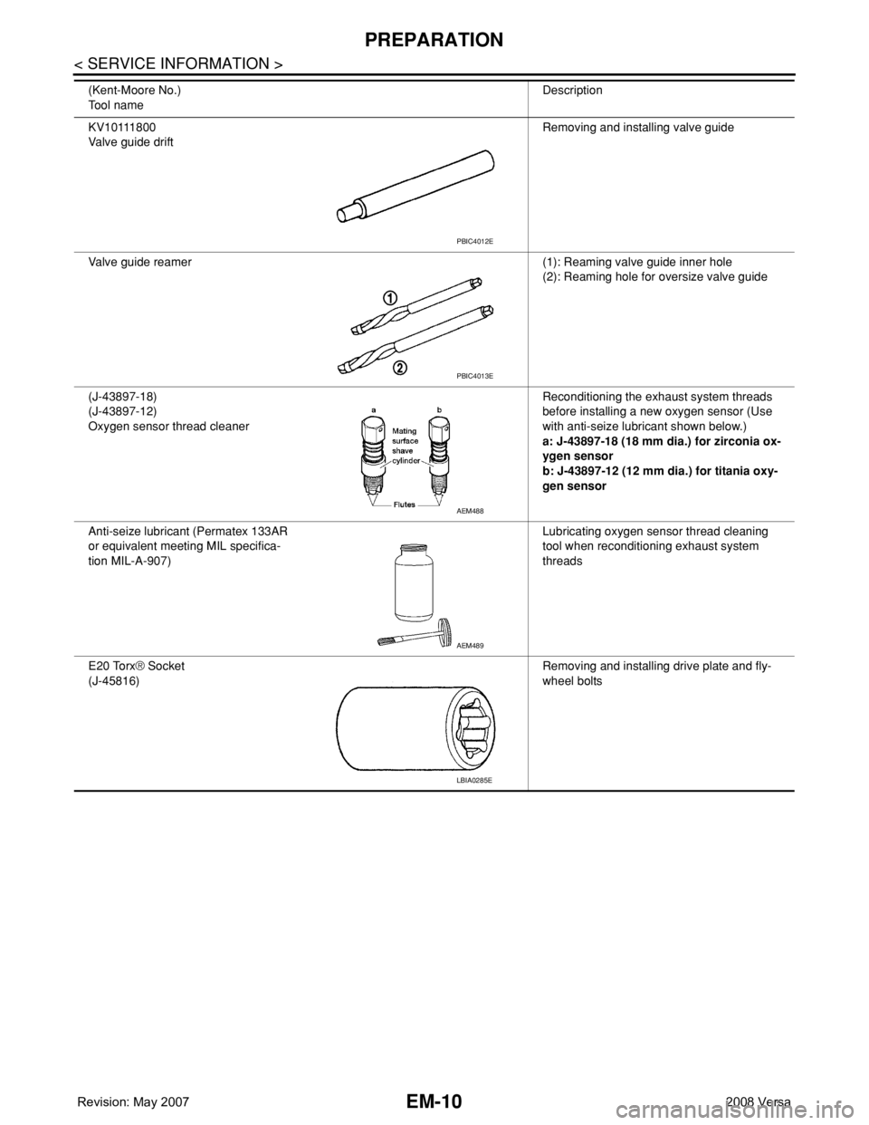
KV10111800
Valve guide driftRemoving and installing valve guide
Valve guide reamer (1): Reaming valve guide inner hole
(2): Reaming hole for oversize valve guide
(J-43897-18)
(J-43897-12)
Oxygen sensor thread cleanerReconditioning the exhaust system threads
before installing a new oxygen sensor (Use
with anti-seize lubricant shown below.)
a: J-43897-18 (18 mm dia.) for zirconia ox-
ygen sensor
b: J-43897-12 (12 mm dia.) for titania oxy-
gen sensor
Anti-seize lubricant (Permatex 133AR
or equivalent meeting MIL specifica-
tion MIL-A-907)Lubricating oxygen sensor thread cleaning
tool when reconditioning exhaust system
threads
E20 Torx® Socket
(J-45816)Removing and installing drive plate and fly-
wheel bolts (Kent-Moore No.)
Tool nameDescription
PBIC4012E
PBIC4013E
AEM488
AEM489
LBIA0285E
Page 1702 of 2771
OIL PAN
EM-25
< SERVICE INFORMATION >
C
D
E
F
G
H
I
J
K
L
MA
EM
N
P O
1. Drain engine oil. Refer to LU-6.
2. Remove engine and transaxle assembly. Refer to EM-72
.
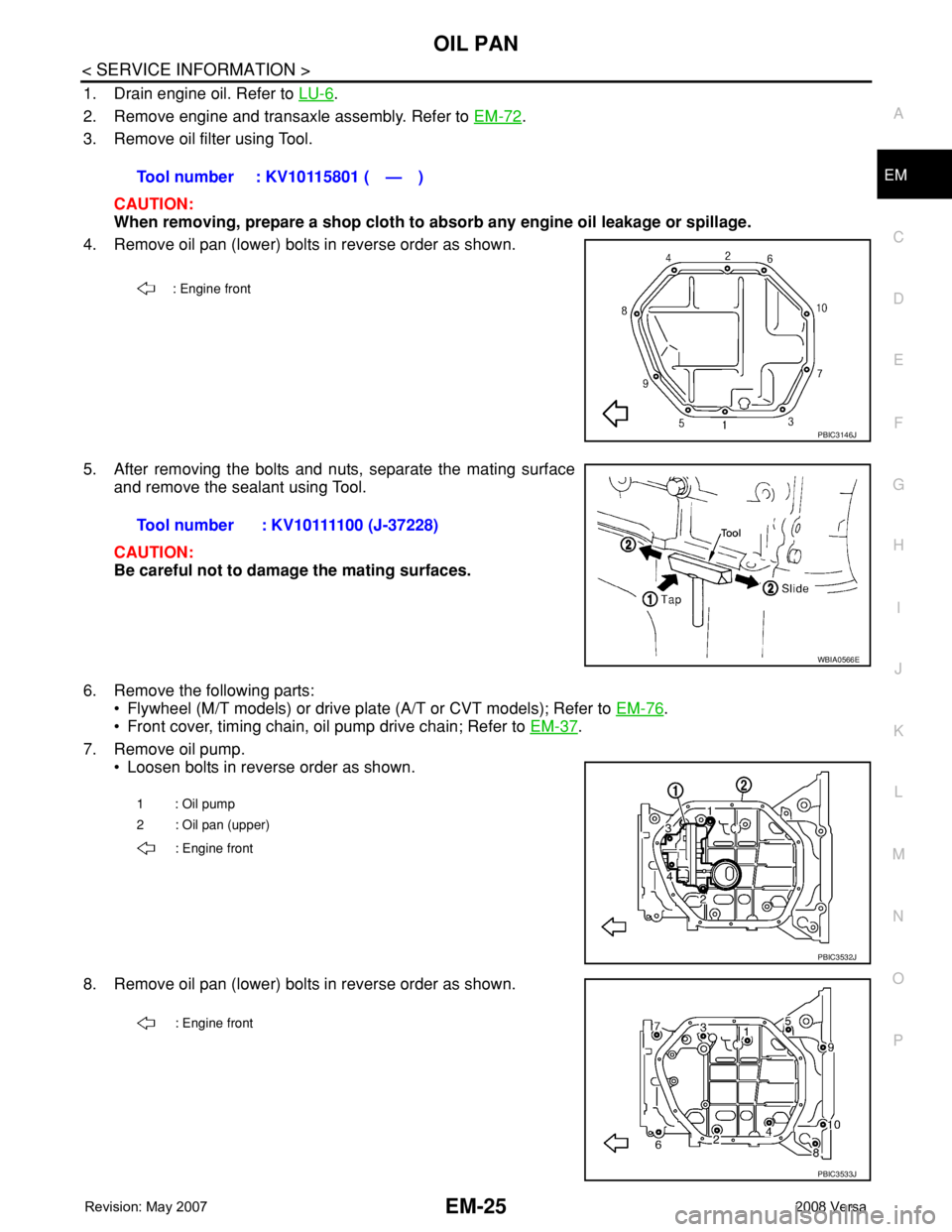
3. Remove oil filter using Tool.
CAUTION:
When removing, prepare a shop cloth to absorb any engine oil leakage or spillage.
4. Remove oil pan (lower) bolts in reverse order as shown.
5. After removing the bolts and nuts, separate the mating surface
and remove the sealant using Tool.
CAUTION:
Be careful not to damage the mating surfaces.
6. Remove the following parts:
• Flywheel (M/T models) or drive plate (A/T or CVT models); Refer to EM-76
.
• Front cover, timing chain, oil pump drive chain; Refer to EM-37
.
7. Remove oil pump.
• Loosen bolts in reverse order as shown.
8. Remove oil pan (lower) bolts in reverse order as shown.Tool number : KV10115801 ( — )
: Engine front
PBIC3146J
Tool number : KV10111100 (J-37228)
WBIA0566E
1: Oil pump
2 : Oil pan (upper)
: Engine front
PBIC3532J
: Engine front
PBIC3533J
Page 1749 of 2771
EM-72
< SERVICE INFORMATION >
ENGINE ASSEMBLY
ENGINE ASSEMBLY
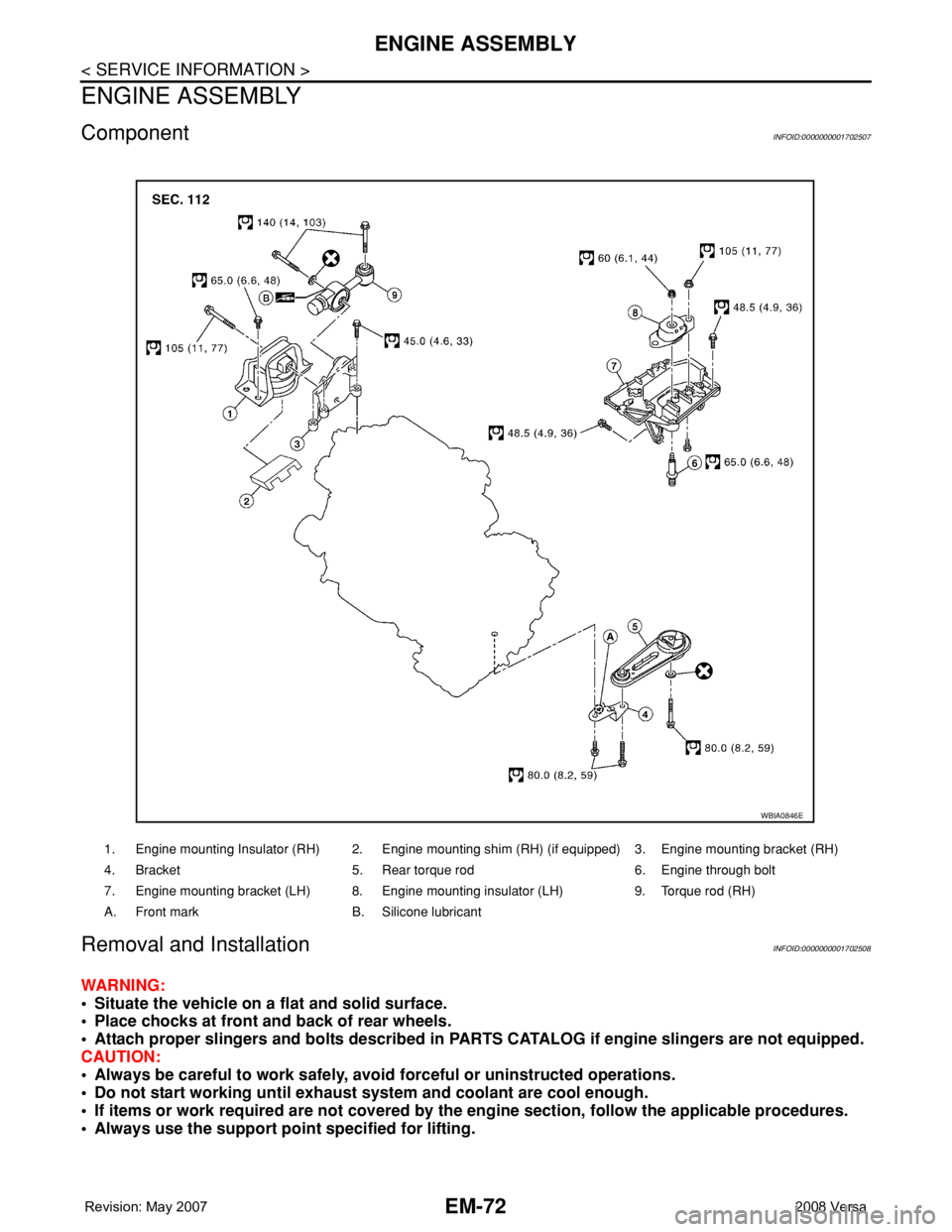
ComponentINFOID:0000000001702507
Removal and InstallationINFOID:0000000001702508
WARNING:
• Situate the vehicle on a flat and solid surface.
• Place chocks at front and back of rear wheels.
• Attach proper slingers and bolts described in PARTS CATALOG if engine slingers are not equipped.
CAUTION:
• Always be careful to work safely, avoid forceful or uninstructed operations.
• Do not start working until exhaust system and coolant are cool enough.
• If items or work required are not covered by the engine section, follow the applicable procedures.
• Always use the support point specified for lifting.
1. Engine mounting Insulator (RH) 2. Engine mounting shim (RH) (if equipped) 3. Engine mounting bracket (RH)
4. Bracket 5. Rear torque rod 6. Engine through bolt
7. Engine mounting bracket (LH) 8. Engine mounting insulator (LH) 9. Torque rod (RH)
A. Front mark B. Silicone lubricant
WBIA0846E
Page 1754 of 2771
CYLINDER BLOCK
EM-77
< SERVICE INFORMATION >
C
D
E
F
G
H
I
J
K
L
MA
EM
N
P O
Disassembly and AssemblyINFOID:0000000001702510
DISASSEMBLY
1. Remove engine and transaxle assembly from vehicle, separate transaxle from engine. Refer to EM-72.
2. Install engine to engine stand as follows;
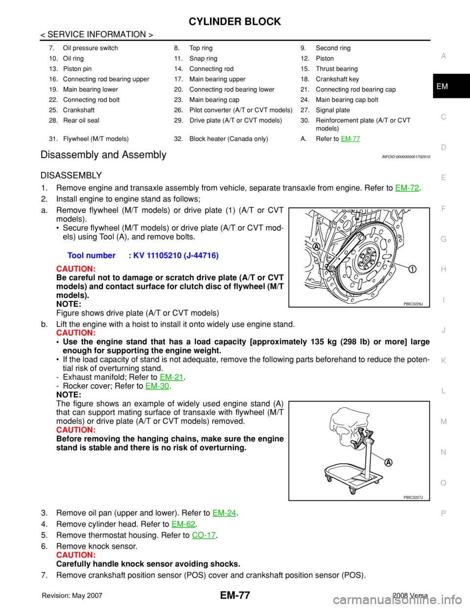
a. Remove flywheel (M/T models) or drive plate (1) (A/T or CVT
models).
• Secure flywheel (M/T models) or drive plate (A/T or CVT mod-
els) using Tool (A), and remove bolts.
CAUTION:
Be careful not to damage or scratch drive plate (A/T or CVT
models) and contact surface for clutch disc of flywheel (M/T
models).
NOTE:
Figure shows drive plate (A/T or CVT models)
b. Lift the engine with a hoist to install it onto widely use engine stand.
CAUTION:
• Use the engine stand that has a load capacity [approximately 135 kg (298 lb) or more] large
enough for supporting the engine weight.
• If the load capacity of stand is not adequate, remove the following parts beforehand to reduce the poten-
tial risk of overturning stand.
- Exhaust manifold; Refer to EM-21
.
- Rocker cover; Refer to EM-30
.
NOTE:
The figure shows an example of widely used engine stand (A)
that can support mating surface of transaxle with flywheel (M/T
models) or drive plate (A/T or CVT models) removed.
CAUTION:
Before removing the hanging chains, make sure the engine
stand is stable and there is no risk of overturning.
3. Remove oil pan (upper and lower). Refer to EM-24
.
4. Remove cylinder head. Refer to EM-62
.
5. Remove thermostat housing. Refer to CO-17
.
6. Remove knock sensor.
CAUTION:
Carefully handle knock sensor avoiding shocks.
7. Remove crankshaft position sensor (POS) cover and crankshaft position sensor (POS).
7. Oil pressure switch 8. Top ring 9. Second ring
10. Oil ring 11. Snap ring 12. Piston
13. Piston pin 14. Connecting rod 15. Thrust bearing
16. Connecting rod bearing upper 17. Main bearing upper 18. Crankshaft key
19. Main bearing lower 20. Connecting rod bearing lower 21. Connecting rod bearing cap
22. Connecting rod bolt 23. Main bearing cap 24. Main bearing cap bolt
25. Crankshaft 26. Pilot converter (A/T or CVT models) 27. Signal plate
28. Rear oil seal 29. Drive plate (A/T or CVT models) 30. Reinforcement plate (A/T or CVT
models)
31. Flywheel (M/T models) 32. Block heater (Canada only) A. Refer to EM-77
Tool number : KV 11105210 (J-44716)
PBIC3226J
PBIC3227J
Page 1761 of 2771
![NISSAN LATIO 2008 Service User Guide EM-84
< SERVICE INFORMATION >
CYLINDER BLOCK
• Using a piston ring compressor [SST: EM03470000 (J-8037)]
(A) or suitable tool, install piston with the front mark on the pis-
ton head facing the fron NISSAN LATIO 2008 Service User Guide EM-84
< SERVICE INFORMATION >
CYLINDER BLOCK
• Using a piston ring compressor [SST: EM03470000 (J-8037)]
(A) or suitable tool, install piston with the front mark on the pis-
ton head facing the fron](/img/5/57360/w960_57360-1760.png)
EM-84
< SERVICE INFORMATION >
CYLINDER BLOCK
• Using a piston ring compressor [SST: EM03470000 (J-8037)]
(A) or suitable tool, install piston with the front mark on the pis-
ton head facing the front of the engine.
CAUTION:
Be careful not to damage the cylinder wall and crankshaft
pin, resulting from an interference of the connecting rod
big end.
22. Install connecting rod cap.
• Match the stamped cylinder number marks (C) on connecting
rod with those on connecting rod cap to install.
23. Tighten connecting rod bolt with the following procedure:
CAUTION:
• Make sure that there is no gap in the thrust surface (A) of
the joint between connecting rod (1) and connecting rod
bearing cap (2) and that these parts are in the correct
position. And then, tighten the connecting rod bolts.
• If the connecting rod bolts are reused, measure the outer
diameter. Refer to EM-93, "
Inspection After Disassembly".
24. Apply new engine oil to the threads and seats of connecting rod
bolts.
25. Tighten bolts in three steps
• After tightening connecting rod bolt, make sure that crankshaft rotates smoothly.
• Check the connecting rod side clearance. Refer to EM-93, "
Inspection After Disassembly".
26. Install oil pan (upper). Refer to EM-24
.
NOTE:
Install the rear oil seal after installing the oil pan (upper).
27. Install rear oil seal. Refer to EM-24
.
28. Install flywheel (M/T models) or drive plate (1) (A/T or CVT mod-
els).
• Secure crankshaft using Tool. (A), and tighten bolts crosswise
over several times.
NOTE:
A/T model shown CVT and M/T similar.
PBIC3244J
A : Front mark (piston)
B : Oil hole
D : Big end diameter grade
E : Small end diameter grade
F : Front mark (connecting rod bearing cap)
PBIC3587J
Step 1 : 27.4 N·m (2.8 kg-m, 20 ft-lb)
Step 2 : 0 N·m (0 kg-m, 0 ft-lb)
Step 3 : 19.6 N·m (2.0 kg-m, 14 ft-lb)
Tool number : KV11105210 (J-44716)PBIC3510J
PBIC3998E
Page 1799 of 2771
PREPARATION
FAX-3
< SERVICE INFORMATION >
C
E
F
G
H
I
J
K
L
MA
B
FA X
N
O
P
PREPARATION
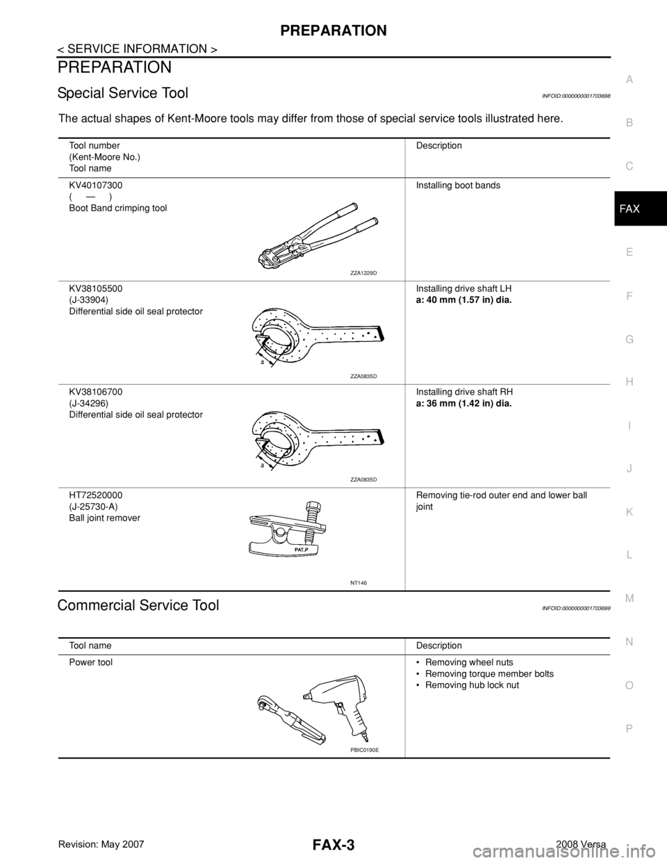
Special Service ToolINFOID:0000000001703698
The actual shapes of Kent-Moore tools may differ from those of special service tools illustrated here.
Commercial Service ToolINFOID:0000000001703699
Tool number
(Kent-Moore No.)
Tool nameDescription
KV40107300
(—)
Boot Band crimping toolInstalling boot bands
KV38105500
(J-33904)
Differential side oil seal protectorInstalling drive shaft LH
a: 40 mm (1.57 in) dia.
KV38106700
(J-34296)
Differential side oil seal protectorInstalling drive shaft RH
a: 36 mm (1.42 in) dia.
HT72520000
(J-25730-A)
Ball joint removerRemoving tie-rod outer end and lower ball
joint
ZZA1229D
ZZA0835D
ZZA0835D
NT146
Tool nameDescription
Power tool• Removing wheel nuts
• Removing torque member bolts
• Removing hub lock nut
PBIC0190E
Page 1802 of 2771
FAX-6
< SERVICE INFORMATION >
FRONT WHEEL HUB AND KNUCKLE
2. Without disassembling the hydraulic lines, remove the torque member bolts using power tool. Then repo-
sition the torque member and brake caliper assembly aside with wire. Refer to BR-23
.
CAUTION:
Do not depress brake pedal while brake caliper is removed.
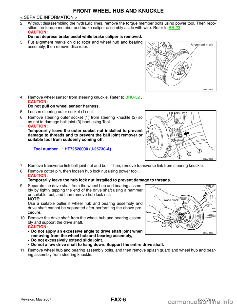
3. Put alignment marks on disc rotor and wheel hub and bearing
assembly, then remove disc rotor.
4. Remove wheel sensor from steering knuckle. Refer to BRC-32
.
CAUTION:
Do not pull on wheel sensor harness.
5. Loosen steering outer socket (1) nut.
6. Remove steering outer socket (1) from steering knuckle (2) so
as not to damage ball joint (3) boot using Tool.
CAUTION:
Temporarily leave the outer socket nut installed to prevent
damage to threads and to prevent the ball joint remover or
suitable tool from suddenly coming off.
7. Remove transverse link ball joint nut and bolt. Then, remove transverse link from steering knuckle.
8. Remove cotter pin, then loosen hub lock nut using power tool.
CAUTION:
Temporarily leave the hub lock nut installed to prevent damage to threads.
9. Separate the drive shaft from the wheel hub and bearing assem-
bly by lightly tapping the end of the drive shaft using a hammer
or suitable tool, and then remove hub lock nut.
NOTE:
Use a suitable puller if wheel hub and bearing assembly and
drive shaft cannot be separated after performing the above pro-
cedure.
10. Remove the drive shaft from the wheel hub and bearing assem-
bly and support the drive shaft.
CAUTION:
• Do not apply an excessive angle to drive shaft joint when
removing from the wheel hub and bearing assembly,
• Do not excessively extend slide joint.
• Do not allow drive shaft to hang down. Support the entire drive shaft.
11. Remove wheel hub and bearing assembly bolts, and then remove splash guard and wheel hub and bear-
ing assembly from steering knuckle.
SDIA1480E
Tool number : HT72520000 (J-25730-A)
SGIA1298E
SDIA1821E
Page 1803 of 2771
FRONT WHEEL HUB AND KNUCKLE
FAX-7
< SERVICE INFORMATION >
C
E
F
G
H
I
J
K
L
MA
B
FA X
N
O
P
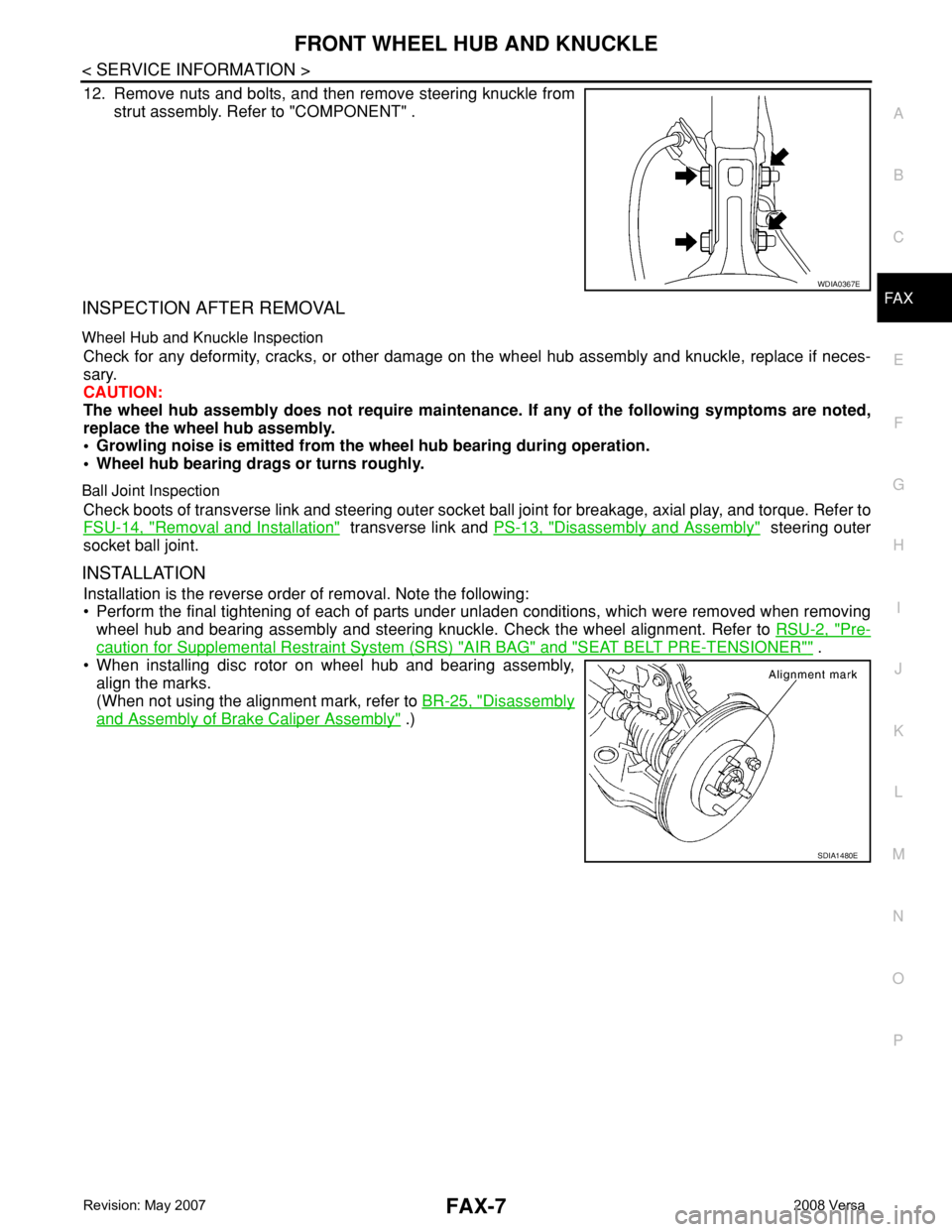
12. Remove nuts and bolts, and then remove steering knuckle from
strut assembly. Refer to "COMPONENT" .
INSPECTION AFTER REMOVAL
Wheel Hub and Knuckle Inspection
Check for any deformity, cracks, or other damage on the wheel hub assembly and knuckle, replace if neces-
sary.
CAUTION:
The wheel hub assembly does not require maintenance. If any of the following symptoms are noted,
replace the wheel hub assembly.
• Growling noise is emitted from the wheel hub bearing during operation.
• Wheel hub bearing drags or turns roughly.
Ball Joint Inspection
Check boots of transverse link and steering outer socket ball joint for breakage, axial play, and torque. Refer to
FSU-14, "
Removal and Installation" transverse link and PS-13, "Disassembly and Assembly" steering outer
socket ball joint.
INSTALLATION
Installation is the reverse order of removal. Note the following:
• Perform the final tightening of each of parts under unladen conditions, which were removed when removing
wheel hub and bearing assembly and steering knuckle. Check the wheel alignment. Refer to RSU-2, "
Pre-
caution for Supplemental Restraint System (SRS) "AIR BAG" and "SEAT BELT PRE-TENSIONER"" .
• When installing disc rotor on wheel hub and bearing assembly,
align the marks.
(When not using the alignment mark, refer to BR-25, "
Disassembly
and Assembly of Brake Caliper Assembly" .)
WDIA0367E
SDIA1480E
Page 1806 of 2771
FAX-10
< SERVICE INFORMATION >
FRONT DRIVE SHAFT
REMOVAL
1. Remove wheel and tire using power tool. Refer to WT-6, "Rotation" .
2. Remove wheel sensor from steering knuckle. Refer to BRC-32, "
Removal and Installation".
CAUTION:
Do not pull on wheel sensor harness.
3. Remove transverse link ball joint nut and bolt. Then, remove transverse link from steering knuckle.
4. Remove cotter pin, then loosen hub lock nut using power tool.
CAUTION:
Temporarily leave the hub lock nut installed to prevent damage to threads.
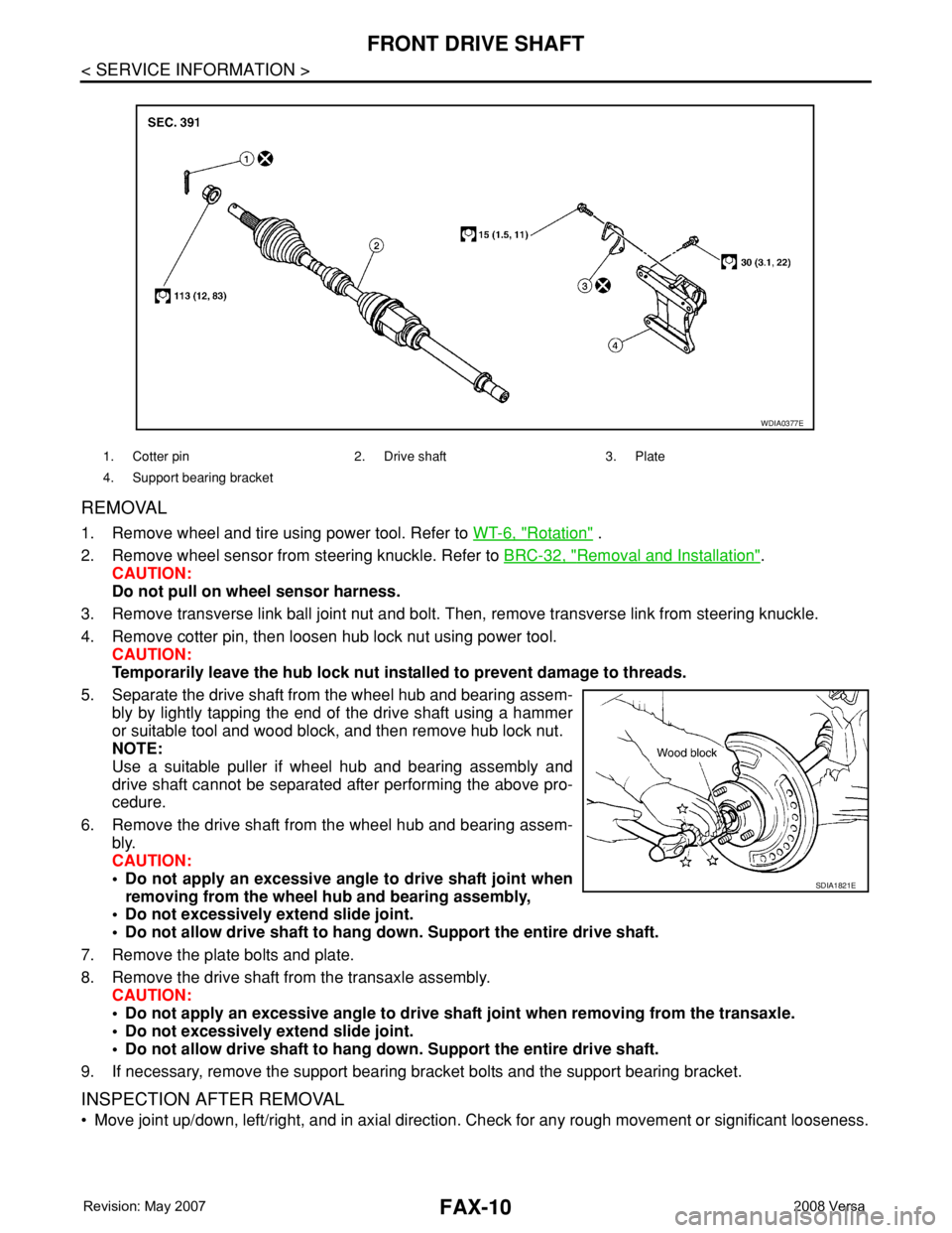
5. Separate the drive shaft from the wheel hub and bearing assem-
bly by lightly tapping the end of the drive shaft using a hammer
or suitable tool and wood block, and then remove hub lock nut.
NOTE:
Use a suitable puller if wheel hub and bearing assembly and
drive shaft cannot be separated after performing the above pro-
cedure.
6. Remove the drive shaft from the wheel hub and bearing assem-
bly.
CAUTION:
• Do not apply an excessive angle to drive shaft joint when
removing from the wheel hub and bearing assembly,
• Do not excessively extend slide joint.
• Do not allow drive shaft to hang down. Support the entire drive shaft.
7. Remove the plate bolts and plate.
8. Remove the drive shaft from the transaxle assembly.
CAUTION:
• Do not apply an excessive angle to drive shaft joint when removing from the transaxle.
• Do not excessively extend slide joint.
• Do not allow drive shaft to hang down. Support the entire drive shaft.
9. If necessary, remove the support bearing bracket bolts and the support bearing bracket.
INSPECTION AFTER REMOVAL
• Move joint up/down, left/right, and in axial direction. Check for any rough movement or significant looseness.
1. Cotter pin 2. Drive shaft 3. Plate
4. Support bearing bracket
WDIA0377E
SDIA1821E
Page 1841 of 2771
FRONT SUSPENSION ASSEMBLY
FSU-7
< SERVICE INFORMATION >
C
D
F
G
H
I
J
K
L
MA
B
FSU
N
O
P
• This may result in an ERROR.
2. Some newer alignment machines are equipped with an optional “Rolling Compensation” method to “com-
pensate” the sensors (alignment targets or head units). Do NOT use this “Rolling Compensation”
method.
• Use the “Jacking Compensation” method. After installing the alignment targets or head units, raise the
vehicle and rotate the wheels 1/2 turn both ways.
• See Instructions in the alignment machine you are using for more information.
CAMBER, CASTER AND KINGPIN INCLINATION ANGLES INSPECTION
• Camber, caster, kingpin inclination angles cannot be adjusted.
• Before inspection, mount front wheels onto turning radius gauge. Mount rear wheels onto a stand that has
same height so vehicle will remain horizontal.
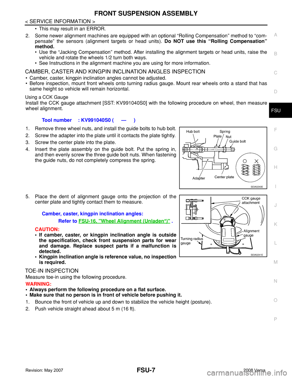
Using a CCK Gauge
Install the CCK gauge attachment [SST: KV991040S0] with the following procedure on wheel, then measure
wheel alignment.
1. Remove three wheel nuts, and install the guide bolts to hub bolt.
2. Screw the adapter into the plate until it contacts the plate tightly.
3. Screw the center plate into the plate.
4. Insert the plate assembly on the guide bolt. Put the spring in,
and then evenly screw the three guide bolt nuts. When fastening
the guide nuts, do not completely compress the spring.
5. Place the dent of alignment gauge onto the projection of the
center plate and tightly contact them to measure.
CAUTION:
• If camber, caster, or kingpin inclination angle is outside
the specification, check front suspension parts for wear
and damage. Replace suspect parts if a malfunction is
detected.
• Kingpin inclination angle is reference value, no inspection
is required.
TOE-IN INSPECTION
Measure toe-in using the following procedure.
WARNING:
• Always perform the following procedure on a flat surface.
• Make sure that no person is in front of vehicle before pushing it.
1. Bounce the front of vehicle up and down to stabilize the vehicle height (posture).
2. Push vehicle straight ahead about 5 m (16 ft).Tool number : KV991040S0 ( — )
SEIA0240E
Camber, caster, kingpin inclination angles:
Refer to FSU-16, "
Wheel Alignment (Unladen*)" .
SEIA0241E