radio NISSAN LATIO 2008 Service Owner's Manual
[x] Cancel search | Manufacturer: NISSAN, Model Year: 2008, Model line: LATIO, Model: NISSAN LATIO 2008Pages: 2771, PDF Size: 60.61 MB
Page 1876 of 2771

SERVICE INFORMATION FOR ELECTRICAL INCIDENT
GI-25
< SERVICE INFORMATION >
C
D
E
F
G
H
I
J
K
L
MB
GI
N
O
P
How to Perform Efficient Diagnosis for an Electrical IncidentINFOID:0000000001702441
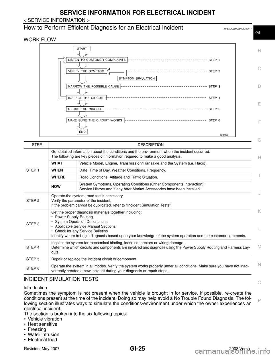
WORK FLOW
INCIDENT SIMULATION TESTS
Introduction
Sometimes the symptom is not present when the vehicle is brought in for service. If possible, re-create the
conditions present at the time of the incident. Doing so may help avoid a No Trouble Found Diagnosis. The fol-
lowing section illustrates ways to simulate the conditions/environment under which the owner experiences an
electrical incident.
The section is broken into the six following topics:
• Vehicle vibration
• Heat sensitive
• Freezing
• Water intrusion
• Electrical load
SGI838
STEP DESCRIPTION
STEP 1Get detailed information about the conditions and the environment when the incident occurred.
The following are key pieces of information required to make a good analysis:
WHATVehicle Model, Engine, Transmission/Transaxle and the System (i.e. Radio).
WHENDate, Time of Day, Weather Conditions, Frequency.
WHERERoad Conditions, Altitude and Traffic Situation.
HOWSystem Symptoms, Operating Conditions (Other Components Interaction).
Service History and if any After Market Accessories have been installed.
STEP 2Operate the system, road test if necessary.
Verify the parameter of the incident.
If the problem cannot be duplicated, refer to “Incident Simulation Tests”.
STEP 3Get the proper diagnosis materials together including:
• Power Supply Routing
• System Operation Descriptions
• Applicable Service Manual Sections
• Check for any Service Bulletins
Identify where to begin diagnosis based upon your knowledge of the system operation and the customer comments.
STEP 4Inspect the system for mechanical binding, loose connectors or wiring damage.
Determine which circuits and components are involved and diagnose using the Power Supply Routing and Harness Lay-
outs.
STEP 5 Repair or replace the incident circuit or component.
STEP 6Operate the system in all modes. Verify the system works properly under all conditions. Make sure you have not inad-
vertently created a new incident during your diagnosis or repair steps.
Page 1878 of 2771

SERVICE INFORMATION FOR ELECTRICAL INCIDENT
GI-27
< SERVICE INFORMATION >
C
D
E
F
G
H
I
J
K
L
MB
GI
N
O
P
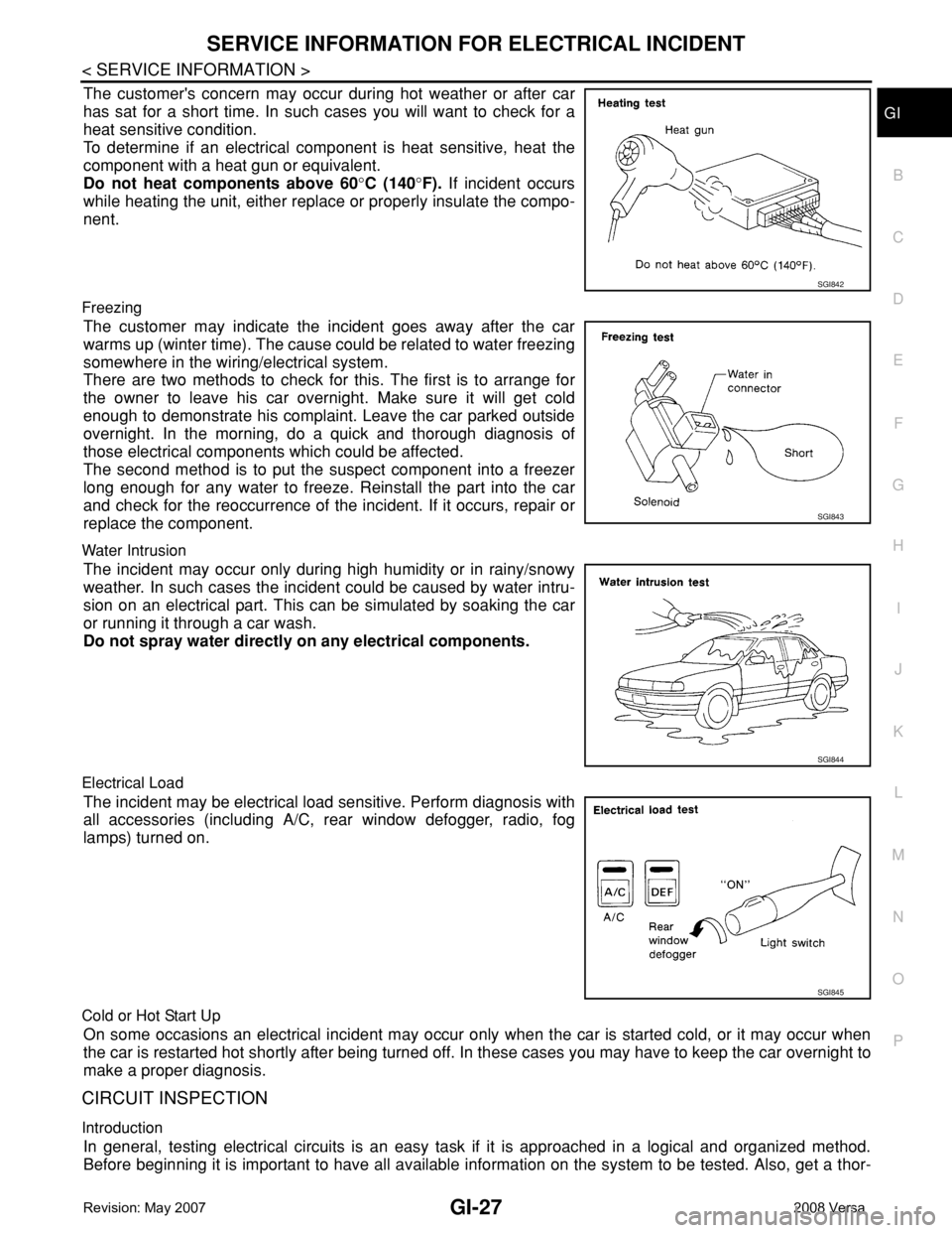
The customer's concern may occur during hot weather or after car
has sat for a short time. In such cases you will want to check for a
heat sensitive condition.
To determine if an electrical component is heat sensitive, heat the
component with a heat gun or equivalent.
Do not heat components above 60°C (140°F). If incident occurs
while heating the unit, either replace or properly insulate the compo-
nent.
Freezing
The customer may indicate the incident goes away after the car
warms up (winter time). The cause could be related to water freezing
somewhere in the wiring/electrical system.
There are two methods to check for this. The first is to arrange for
the owner to leave his car overnight. Make sure it will get cold
enough to demonstrate his complaint. Leave the car parked outside
overnight. In the morning, do a quick and thorough diagnosis of
those electrical components which could be affected.
The second method is to put the suspect component into a freezer
long enough for any water to freeze. Reinstall the part into the car
and check for the reoccurrence of the incident. If it occurs, repair or
replace the component.
Water Intrusion
The incident may occur only during high humidity or in rainy/snowy
weather. In such cases the incident could be caused by water intru-
sion on an electrical part. This can be simulated by soaking the car
or running it through a car wash.
Do not spray water directly on any electrical components.
Electrical Load
The incident may be electrical load sensitive. Perform diagnosis with
all accessories (including A/C, rear window defogger, radio, fog
lamps) turned on.
Cold or Hot Start Up
On some occasions an electrical incident may occur only when the car is started cold, or it may occur when
the car is restarted hot shortly after being turned off. In these cases you may have to keep the car overnight to
make a proper diagnosis.
CIRCUIT INSPECTION
Introduction
In general, testing electrical circuits is an easy task if it is approached in a logical and organized method.
Before beginning it is important to have all available information on the system to be tested. Also, get a thor-
SGI842
SGI843
SGI844
SGI845
Page 2479 of 2771

PG-46
< SERVICE INFORMATION >
HARNESS
G4 B2 GR/2 : Rear bumper antenna
C4 B4 W/8 : To D201
C4 B5 — : Body ground
E4 B6 W/1 : Rear door switch LH
C4 B7 — : Body ground
C4 B8 W/3 : Front door switch LH
C4 B9 Y/12 : Air bag diagnosis sensor unit
C4 B10 Y/2 : Front LH side air bag module
F3 B13 W/3 : Seat belt buckle switch LH
C4 B14 Y/2 : Front LH seat belt pre-tensioner
C5 B15 Y/2 : LH side air bag (satellite) sensor
G4 B16 BR/2 : License plate lamp LH
G4 B17 BR/2 : License plate lamp RH
F3 B19 — : Body ground
F3 B21 W/2 : Luggage room lamp
A4 B23 W/16 : To M15
A4 B24 W/24 : To M16
F3 B25 BR/6 : Rear combination lamp LH
F3 B26 Y/2 : LH side curtain air bag module
F4 B29 W/6 : Subwoofer
F4 B30 W/16 : Satellite radio tuner
Page 2481 of 2771

PG-48
< SERVICE INFORMATION >
HARNESS
C4 B8 W/3 : Front door switch LH
B3 B9 Y/12 : Air bag diagnosis sensor unit
B3 B10 Y/2 : Front LH side air bag module
B4 B13 W/3 : Seat belt buckle switch LH
C4 B14 Y/2 : Front LH seat belt pre-tensioner
C5 B15 Y/2 : LH side air bag (satellite) sensor
E3 B19 — : Body ground
F2 B21 W/2 : Luggage room lamp
A4 B23 W/16 : To M15
A4 B24 W/24 : To M16
G4 B25 BR/6 : Rear combination lamp LH
E3 B26 Y/2 : LH side curtain air bag module
E4 B30 W/16 : Satellite radio tuner
F2 B31 W/2 : High mounted stop lamp
F3 B32 BR/2 : Intelligent key warning buzzer (trunk)
Page 2716 of 2771

WT-8
< SERVICE INFORMATION >
TIRE PRESSURE MONITORING SYSTEM
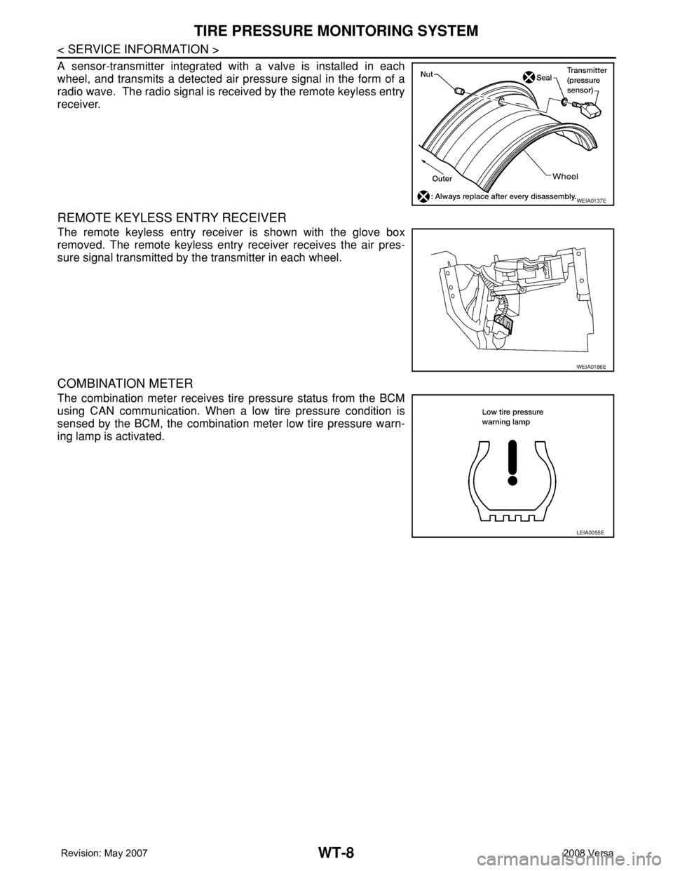
A sensor-transmitter integrated with a valve is installed in each
wheel, and transmits a detected air pressure signal in the form of a
radio wave. The radio signal is received by the remote keyless entry
receiver.
REMOTE KEYLESS ENTRY RECEIVER
The remote keyless entry receiver is shown with the glove box
removed. The remote keyless entry receiver receives the air pres-
sure signal transmitted by the transmitter in each wheel.
COMBINATION METER
The combination meter receives tire pressure status from the BCM
using CAN communication. When a low tire pressure condition is
sensed by the BCM, the combination meter low tire pressure warn-
ing lamp is activated.
WEIA0137E
WEIA0186E
LEIA0055E