engine NISSAN LATIO 2008 Service Repair Manual
[x] Cancel search | Manufacturer: NISSAN, Model Year: 2008, Model line: LATIO, Model: NISSAN LATIO 2008Pages: 2771, PDF Size: 60.61 MB
Page 1290 of 2771

EC-216
< SERVICE INFORMATION >
DTC P0131 A/F SENSOR 1
Do not use ECM ground terminals when measuring input/output voltage. Doing so may result in dam-
age to the ECM's transistor. Use a ground other than ECM terminals, such as the ground.
: Average voltage for pulse signal (Actual pulse signal can be confirmed by oscilloscope.)
Diagnosis ProcedureINFOID:0000000001702717
1.CHECK GROUND CONNECTIONS
1. Turn ignition switch OFF.
2. Loosen and retighten ground screw on the body.
Refer to EC-142, "
Ground Inspection".
OK or NG
OK >> GO TO 2.
NG >> Repair or replace ground connections.
2.CHECK AIR FUEL RATIO (A/F) SENSOR 1 POWER SUPPLY CIRCUIT
1. Disconnect A/F sensor 1 harness connector (1).
2. Turn ignition switch ON.
TERMI-
NAL
NO.WIRE
COLORITEM CONDITION DATA (DC Voltage)
3 G A/F sensor 1 heater[Engine is running]
•Warm-up condition
• Idle speed
(More than 140 seconds after starting
engine)Approximately 2.9 - 8.8V
49 W A/F sensor 1[Engine is running]
•Warm-up condition
• Engine speed: 2,000 rpmApproximately 1.8V
Output voltage varies with air fuel
ratio.
53 B A/F sensor 1[Ignition switch: ON]Approximately 2.2V
PBIA8148J
:Vehicle front
1. Body ground E24 2. Engine ground F9 3. Engine ground F16
4. Body ground E15
BBIA0698E
BBIA0699E
Page 1293 of 2771
 sensor 1 is a planar")
DTC P0132 A/F SENSOR 1
EC-219
< SERVICE INFORMATION >
C
D
E
F
G
H
I
J
K
L
MA
EC
N
P O
DTC P0132 A/F SENSOR 1
Component DescriptionINFOID:0000000001702719
The air fuel ratio (A/F) sensor 1 is a planar one-cell limit current sen-
sor. The sensor element of the A/F sensor 1 is composed an elec-
trode layer, which transports ions. It has a heater in the element.
The sensor is capable of precise measurement = 1, but also in the
lean and rich range. Together with its control electronics, the sensor
outputs a clear, continuous signal throughout a wide range.
The exhaust gas components diffuse through the diffusion layer at
the sensor cell. An electrode layer is applied voltage, and this current
relative oxygen density in lean. Also this current relative hydrocar-
bon density in rich.
Therefore, the A/F sensor 1 is able to indicate air fuel ratio by this
electrode layer of current. In addition, a heater is integrated in the
sensor to ensure the required operating temperature of about 800°C
(1,472°F).
CONSULT-II Reference Value in Data Monitor ModeINFOID:0000000001702720
Specification data are reference values.
On Board Diagnosis LogicINFOID:0000000001702721
To judge the malfunction, the diagnosis checks that the A/F signal computed by ECM from the air fuel ratio (A/
F) sensor 1 signal is not inordinately high.
DTC Confirmation ProcedureINFOID:0000000001702722
NOTE:
If DTC Confirmation Procedure has been previously conducted, always turn ignition switch OFF and wait at
least 10 seconds before conducting the next test.
TESTING CONDITION:
Before performing the following procedure, confirm that battery voltage is more than 11V at idle.
WITH CONSULT-II
1. Start engine and warm it up to normal operating temperature.
2. Select “A/F SEN1 (B1)” in “DATA MONITOR” mode with CONSULT-II.
PBIB3353E
PBIB3354E
MONITOR ITEM CONDITION SPECIFICATION
A/F SEN1 (B1) • Engine: After warming upMaintaining engine speed at
2,000 rpmFluctuates around 2.2V
DTC No.Trouble diagnosis
nameDTC detecting condition Possible Cause
P0132
0132Air fuel ratio (A/F) sen-
sor 1 circuit high volt-
ageThe A/F signal computed by ECM from the A/F
sensor 1 signal is constantly approx. 5V.• Harness or connectors
[Air fuel ratio (A/F) sensor circuit is open
or shorted.]
• Air fuel ratio (A/F) sensor 1
Page 1294 of 2771
” indication.
If the indication is constantly approx. 5V, go to EC-222, \"
Diagno-
sis Procedure\".
If the indic")
EC-220
< SERVICE INFORMATION >
DTC P0132 A/F SENSOR 1
3. Check “A/F SEN1 (B1)” indication.
If the indication is constantly approx. 5V, go to EC-222, "
Diagno-
sis Procedure".
If the indication is not constantly approx. 5V, go to next step.
4. Turn ignition switch OFF, wait at least 10 seconds and then
restart engine.
5. Drive and accelerate vehicle to more than 40 km/h (25 MPH)
within 20 seconds after restarting engine.
6. Maintain the following conditions for about 20 consecutive sec-
onds.
NOTE:
•Keep the accelerator pedal as steady as possible during the cruising.
•If this procedure is not completed within 1 minute after restarting engine at step 4, return to step
4.
7. If 1st trip DTC is displayed, go to EC-222, "
Diagnosis Procedure".
WITH GST
Follow the procedure “WITH CONSULT-II” above.
ENG SPEED 1,000 - 3,200 rpm
VHCL SPEED SE More than 40 km/h (25 MPH)
B/FUEL SCHDL 1.5 - 9.0 msec
Shift lever Suitable position
SEF581Z
Page 1296 of 2771

EC-222
< SERVICE INFORMATION >
DTC P0132 A/F SENSOR 1
Do not use ECM ground terminals when measuring input/output voltage. Doing so may result in dam-
age to the ECM's transistor. Use a ground other than ECM terminals, such as the ground.
: Average voltage for pulse signal (Actual pulse signal can be confirmed by oscilloscope.)
Diagnosis ProcedureINFOID:0000000001702724
1.CHECK GROUND CONNECTIONS
1. Turn ignition switch OFF.
2. Loosen and retighten three ground screws on the body.
Refer to EC-142, "
Ground Inspection".
OK or NG
OK >> GO TO 2.
NG >> Repair or replace ground connections.
2.CHECK AIR FUEL RATIO (A/F) SENSOR 1 POWER SUPPLY CIRCUIT
1. Disconnect A/F sensor 1 harness connector (1).
2. Turn ignition switch ON.
TERMI-
NAL
NO.WIRE
COLORITEM CONDITION DATA (DC Voltage)
3 G A/F sensor 1 heater[Engine is running]
•Warm-up condition
• Idle speed
(More than 140 seconds after starting
engine)Approximately 2.9 - 8.8V
49 W A/F sensor 1[Engine is running]
•Warm-up condition
• Engine speed: 2,000 rpmApproximately 1.8V
Output voltage varies with air fuel
ratio.
53 B A/F sensor 1[Ignition switch: ON]Approximately 2.2V
PBIA8148J
:Vehicle front
1. Body ground E24 2. Engine ground F9 3. Engine ground F16
4. Body ground E15
BBIA0698E
BBIA0699E
Page 1299 of 2771
 sensor 1 is a planar")
DTC P0133 A/F SENSOR 1
EC-225
< SERVICE INFORMATION >
C
D
E
F
G
H
I
J
K
L
MA
EC
N
P O
DTC P0133 A/F SENSOR 1
Component DescriptionINFOID:0000000001702726
The air fuel ratio (A/F) sensor 1 is a planar one-cell limit current sen-
sor. The sensor element of the A/F sensor 1 is composed an elec-
trode layer, which transports ions. It has a heater in the element.
The sensor is capable of precise measurement = 1, but also in the
lean and rich range. Together with its control electronics, the sensor
outputs a clear, continuous signal throughout a wide range.
The exhaust gas components diffuse through the diffusion layer at
the sensor cell. An electrode layer is applied voltage, and this current
relative oxygen density in lean. Also this current relative hydrocar-
bon density in rich.
Therefore, the A/F sensor 1 is able to indicate air fuel ratio by this
electrode layer of current. In addition, a heater is integrated in the
sensor to ensure the required operating temperature of about 800°C
(1,472°F).
CONSULT-II Reference Value in Data Monitor ModeINFOID:0000000001702727
Specification data are reference values.
On Board Diagnosis LogicINFOID:0000000001702728
To judge the malfunction of air fuel ratio (A/F) sensor 1, this diagnosis measures response time of the A/F sig-
nal computed by ECM from the air fuel ratio (A/F) sensor 1 signal. The time is compensated by engine operat-
ing (speed and load), fuel feedback control constant, and the air fuel ratio (A/F) sensor 1 temperature index.
Judgment is based on whether the compensated time (the A/F sensor 1 signal cycling time index) is inordi-
nately long or not.
DTC Confirmation ProcedureINFOID:0000000001702729
NOTE:
PBIB3353E
PBIB3354E
MONITOR ITEM CONDITION SPECIFICATION
A/F SEN1 (B1) • Engine: After warming upMaintaining engine speed at
2,000 rpmFluctuates around 2.2V
DTC No.Trouble diag-
nosis nameDTC detecting condition Possible Cause
P0133
0133Air fuel ratio
(A/F) sensor 1
circuit slow re-
sponseThe response of the A/F signal computed by ECM from
A/F sensor 1 signal takes more than the specified time.• Harness or connectors
[Air fuel ratio (A/F) sensor circuit is open
or shorted.]
• Air fuel ratio (A/F) sensor 1
• Air fuel ratio (A/F) sensor heater 1
• Fuel pressure
• Fuel injector
• Intake air leaks
• Exhaust gas leaks
•PCV
• Mass air flow sensor
Page 1300 of 2771

EC-226
< SERVICE INFORMATION >
DTC P0133 A/F SENSOR 1
If DTC Confirmation Procedure has been previously conducted, always turn ignition switch OFF and wait at
least 10 seconds before conducting the next test.
TESTING CONDITION:
Before performing the following procedure, confirm that battery voltage is more than 11V at idle.
WITH CONSULT-II
1. Start engine and warm it up to normal operating temperature.
2. Turn ignition switch OFF and wait at least 10 seconds.
3. Start engine and keep the engine speed between 3,500 and 4,000 rpm for at least 1minute under no load.
4. Let engine idle for 1 minute.
5. Select “A/F SEN1(B1) P1278/P1279” of “A/F SEN1” in “DTC WORK SUPPORT” mode with CONSULT-II.
6. Touch “START”.
If “COMPLETED” appears on CONSULT-II screen, go to step
10.
If “COMPLETED” does not appear on CONSULT-II screen, go to
the following step.
7. After perform the following procedure, “TESTING” will be dis-
played on the CONSULT-II screen.
a. Increase the engine speed up to 4,000 to 5,000 rpm and keep it
for 10 seconds.
b. Fully release accelerator pedal and then let engine idle for about
10 seconds.
If “TESTING” is not displayed after 10 seconds, refer to EC-
127.
8. Wait for about 20 seconds at idle at under the condition that
“TESTING” is displayed on the CONSULT-II screen.
9. Make sure that “TESTING” changes to “COMPLETED”.
If “TESTING” changed to “OUT OF CONDITION”, refer to
EC-127
.
10. Make sure that “OK” is displayed after touching “SELF-DIAG
RESULT”.
If “NG” is displayed, go to EC-229, "
Diagnosis Procedure".
WITH GST
1. Start engine and warm it up to normal operating temperature.
2. Select Service $01 with GST.
3. Calculate the total value of “Short term fuel trim” and “Long term fuel trim” indications.
Make sure that the total percentage should be within ±15%.
If OK, go to the following step.
If NG, check the following.
• Intake air leaks
• Exhaust gas leaks
• Incorrect fuel pressure
PBIB0756E
PBIB1925E
PBIB0758E
Page 1301 of 2771

DTC P0133 A/F SENSOR 1
EC-227
< SERVICE INFORMATION >
C
D
E
F
G
H
I
J
K
L
MA
EC
N
P O
• Lack of fuel
• Fuel injector
• Incorrect PCV hose connection
• PCV valve
• Mass air flow sensor
4. Turn ignition switch OFF and wait at least 10 seconds.
5. Start engine and keep the engine speed between 3,500 and 4,000 rpm for at least 1minute under no load.
6. Let engine idle for 1 minute.
7. Increase the engine speed up to 4,000 to 5,000 rpm and keep it for 10 seconds.
8. Fully release accelerator pedal and then let engine idle for about 1 minute.
9. Select Service $07 with GST.
If 1st trip DTC is detected, go to EC-229, "
Diagnosis Procedure".
Page 1303 of 2771
DTC P0133 A/F SENSOR 1
EC-229
< SERVICE INFORMATION >
C
D
E
F
G
H
I
J
K
L
MA
EC
N
P O
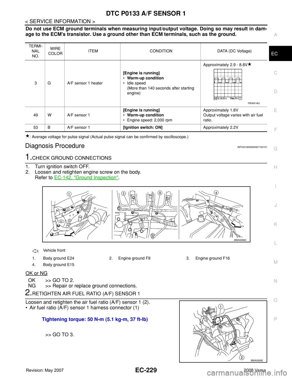
Do not use ECM ground terminals when measuring input/output voltage. Doing so may result in dam-
age to the ECM's transistor. Use a ground other than ECM terminals, such as the ground.
: Average voltage for pulse signal (Actual pulse signal can be confirmed by oscilloscope.)
Diagnosis ProcedureINFOID:0000000001702731
1.CHECK GROUND CONNECTIONS
1. Turn ignition switch OFF.
2. Loosen and retighten engine screw on the body.
Refer to EC-142, "
Ground Inspection".
OK or NG
OK >> GO TO 2.
NG >> Repair or replace ground connections.
2.RETIGHTEN AIR FUEL RATIO (A/F) SENSOR 1
Loosen and retighten the air fuel ratio (A/F) sensor 1 (2).
• Air fuel ratio (A/F) sensor 1 harness connector (1)
>> GO TO 3.
TERMI-
NAL
NO.WIRE
COLORITEM CONDITION DATA (DC Voltage)
3 G A/F sensor 1 heater[Engine is running]
•Warm-up condition
• Idle speed
(More than 140 seconds after starting
engine)Approximately 2.9 - 8.8V
49 W A/F sensor 1[Engine is running]
•Warm-up condition
• Engine speed: 2,000 rpmApproximately 1.8V
Output voltage varies with air fuel
ratio.
53 B A/F sensor 1[Ignition switch: ON]Approximately 2.2V
PBIA8148J
:Vehicle front
1. Body ground E24 2. Engine ground F9 3. Engine ground F16
4. Body ground E15
BBIA0698E
Tightening torque: 50 N-m (5.1 kg-m, 37 ft-lb)
BBIA0699E
Page 1304 of 2771
.
OK or NG
OK >")
EC-230
< SERVICE INFORMATION >
DTC P0133 A/F SENSOR 1
3.CHECK EXHAUST GAS LEAK
1. Start engine and run it at idle.
2. Listen for an exhaust gas leak before three way catalyst (manifold).
OK or NG
OK >> GO TO 4.
NG >> Repair or replace.
4.CHECK FOR INTAKE AIR LEAK
Listen for an intake air leak after the mass air flow sensor.
OK or NG
OK >> GO TO 5.
NG >> Repair or replace.
5.CLEAR THE SELF-LEARNING DATA
With CONSULT-II
1. Start engine and warm it up to normal operating temperature.
2. Select “SELF-LEARNING CONT” in “WORK SUPPORT” mode with CONSULT-II.
3. Clear the self-learning control coefficient by touching “CLEAR”
or “START”.
4. Run engine for at least 10 minutes at idle speed.
Is the 1st trip DTC P0171 or P0172 detected? Is it difficult to
start engine?
Without CONSULT-II
1. Start engine and warm it up to normal operating temperature.
2. Turn ignition switch OFF.
3. Disconnect mass air flow sensor (1) harness connector, and
restart and run engine for at least 5 seconds at idle speed.
4. Stop engine and reconnect mass air flow sensor harness con-
nector.
5. Make sure DTC P0102 is displayed.
6. Erase the DTC memory. Refer to EC-47, "
Emission-related
Diagnostic Information".
7. Make sure DTC P0000 is displayed.
8. Run engine for at least 10 minutes at idle speed.
Is the 1st trip DTC P0171 or P0172 detected? Is it difficult to
start engine?
Ye s o r N o
Yes >> Perform trouble diagnosis for DTC P0171, P0172. Refer to EC-257or EC-264.
No >> GO TO 6.
PBIB1216E
SEF215Z
BBIA0701E
Page 1307 of 2771

DTC P0137 HO2S2
EC-233
< SERVICE INFORMATION >
C
D
E
F
G
H
I
J
K
L
MA
EC
N
P O
DTC P0137 HO2S2
Component DescriptionINFOID:0000000001702733
The heated oxygen sensor 2, after three way catalyst (manifold),
monitors the oxygen level in the exhaust gas.
Even if switching characteristics of the air fuel ratio (A/F) sensor 1
are shifted, the air/fuel ratio is controlled to stoichiometric, by the sig-
nal from the heated oxygen sensor 2.
This sensor is made of ceramic zirconia. The zirconia generates volt-
age from approximately 1V in richer conditions to 0V in leaner condi-
tions.
Under normal conditions the heated oxygen sensor 2 is not used for
engine control operation.
CONSULT-II Reference Value in Data Monitor ModeINFOID:0000000001702734
Specification data are reference values.
On Board Diagnosis LogicINFOID:0000000001702735
The heated oxygen sensor 2 has a much longer switching time
between rich and lean than the air fuel ratio (A/F) sensor 1. The oxy-
gen storage capacity before the three way catalyst (manifold) causes
the longer switching time. To judge the malfunctions of heated oxy-
gen sensor 2, ECM monitors whether the maximum voltage of the
sensor is sufficiently high during the various driving condition such
as fuel-cut.
DTC Confirmation ProcedureINFOID:0000000001702736
NOTE:
If DTC confirmation Procedure has been previously conducted, always turn ignition switch OFF and wait at
least 10 seconds before conducting the next test.
WITH CONSULT-II
TESTING CONDITION:
For the best results, perform DTC WORK SUPPORT at a temperature of 0 to 30°C (32 to 86°F).
SEF327R
MONITOR ITEM CONDITION SPECIFICATION
HO2S2 (B1) • Revving engine from idle to 3,000 rpm quickly after the following
conditions are met.
- Engine: After warming up
- Keeping the engine speed between 3,500 and 4,000 rpm for 1
minute and at idle for 1 minute under no load0 - 0.3V ←→ Approx. 0.6 - 1.0V
HO2S2 MNTR (B1) LEAN ←→ RICH
SEF259VA
DTC No. Trouble diagnosis name DTC detecting condition Possible cause
P0137
0137Heated oxygen sensor 2 cir-
cuit low voltageThe maximum voltage from the sensor is not
reached to the specified voltage.• Harness or connectors
(Heated oxygen sensor 2 circuit open or
shorted.)
• Heated oxygen sensor 2
• Fuel pressure
• Fuel injector
• Intake air leaks