brake light NISSAN LATIO 2008 Service Repair Manual
[x] Cancel search | Manufacturer: NISSAN, Model Year: 2008, Model line: LATIO, Model: NISSAN LATIO 2008Pages: 2771, PDF Size: 60.61 MB
Page 1 of 2771
-1
QUICK REFERENCE INDEX
AGENERAL INFORMATIONGIGeneral Information
BENGINEEMEngine Mechanical
LUEngine Lubrication System
COEngine Cooling System
ECEngine Control System
FLFuel System
EXExhaust System
ACCAccelerator Control System
CTRANSMISSION/
TRANSAXLECLClutch System
MTManual Transaxle
ATAutomatic Transaxle
CVTCVT
DDRIVELINE/AXLEFAXFront Axle
RAXRear Axle
ESUSPENSIONFSUFront Suspension
RSURear Suspension
WTRoad Wheels & Tires
FBRAKESBRBrake System
PBParking Brake System
BRCBrake Control System
GSTEERINGPSPower Steering System
STCSteering Control System
HRESTRAINTSSBSeat Belts
SRSSupplemental Restraint System (SRS)
IBODYBLBody, Lock & Security System
GWGlasses, Window System & Mirrors
RFRoof
EIExterior & Interior
IPInstrument Panel
SESeat
JAIR CONDITIONERMTCManual Air Conditioner
KELECTRICALSCStarting & Charging System
LTLighting System
DIDriver Information System
WWWiper, Washer & Horn
BCSBody Control System
LANLAN System
AVAudio Visual, Navigation & Telephone System
ACSAuto Cruise Control System
PGPower Supply, Ground & Circuit Elements
LMAINTENANCEMAMaintenance
Edition: May 2007
Revision: May 2007
Publication No. SM8E-1C11U0
B
D
© 2007 NISSAN NORTH AMERICA, INC.
All rights reserved. No part of this Service Manual may be reproduced or stored in a retrieval system, or transmitted in any
form, or by any means, electronic, mechanical, photo-copying, recording or otherwise, without the prior written permission
of Nissan North America Inc.
A
C
E
F
G
H
I
J
K
L
M
Page 15 of 2771

AT-3
D
E
F
G
H
I
J
K
L
MA
B
AT
N
O
P N Wiring Diagram - AT - SSV/B ................................
140
Diagnosis Procedure .............................................141
Component Inspection ..........................................142
DTC P1760 OVERRUN CLUTCH SOLENOID
VALVE ..............................................................
144
Description ............................................................144
CONSULT-III Reference Value in Data Monitor
Mode .....................................................................
144
On Board Diagnosis Logic ....................................144
Possible Cause .....................................................144
DTC Confirmation Procedure ................................144
Wiring Diagram - AT - OVRCSV ...........................145
Diagnosis Procedure .............................................146
Component Inspection ..........................................147
DTC VEHICLE SPEED SENSOR MTR ............149
Description ............................................................149
CONSULT-III Reference Value in Data Monitor
Mode .....................................................................
149
On Board Diagnosis Logic ....................................149
Possible Cause .....................................................149
DTC Confirmation Procedure ................................149
Wiring Diagram - AT - VSSMTR ...........................150
Diagnosis Procedure .............................................151
DTC BATT/FLUID TEMP SEN (A/T FLUID
TEMP SENSOR CIRCUIT AND TCM POWER
SOURCE) .........................................................
152
Description ............................................................152
CONSULT-III Reference Value in Data Monitor
Mode .....................................................................
152
On Board Diagnosis Logic ....................................152
Possible Cause .....................................................152
DTC Confirmation Procedure ................................152
Wiring Diagram - AT - BA/FTS ..............................153
Diagnosis Procedure .............................................154
Component Inspection ..........................................156
DTC TURBINE REVOLUTION SENSOR .........158
Description ............................................................158
CONSULT-III Reference Value in Data Monitor
Mode .....................................................................
158
On Board Diagnosis Logic ....................................158
Possible Cause .....................................................158
DTC Confirmation Procedure ................................158
Wiring Diagram - AT - PT/SEN .............................159
Diagnosis Procedure .............................................160
CONTROL UNIT (RAM), CONTROL UNIT
(ROM) ...............................................................
163
Description ............................................................163
On Board Diagnosis Logic ....................................163
Possible Cause .....................................................163
DTC Confirmation Procedure ................................163
Diagnosis Procedure .............................................163
MAIN POWER SUPPLY AND GROUND CIR-
CUIT ..................................................................
164
Wiring Diagram - AT - MAIN .................................164
Diagnosis Procedure .............................................165
PNP, OD SWITCH AND CLOSED THROT-
TLE, WIDE OPEN THROTTLE POSITION
SIGNAL CIRCUIT ............................................
167
CONSULT-III Reference Value in Data Monitor
Mode ......................................................................
167
TCM Terminal and Reference Value .....................167
Diagnosis Procedure .............................................167
Component Inspection ...........................................171
SHIFT POSITION INDICATOR CIRCUIT ........172
Description .............................................................172
CONSULT-III Reference Value in Data Monitor
Mode ......................................................................
172
Diagnosis Procedure .............................................172
TROUBLE DIAGNOSIS FOR SYMPTOMS ....173
Wiring Diagram - AT - NONDTC ...........................173
OD OFF Indicator Lamp Does Not Come On ........176
Engine Cannot Be Started in "P" and "N" Position ..178
In "P" Position, Vehicle Moves Forward or Back-
ward When Pushed ...............................................
179
In "N" Position, Vehicle Moves ..............................179
Large Shock "N" → "R" Position ............................180
Vehicle Does Not Creep Backward in "R" Position ..181
Vehicle Does Not Creep Forward in "D", "2" or "1"
Position ..................................................................
182
Vehicle Cannot Be Started from D1 .......................183
A/T Does Not Shift: D1→ D2or Does Not Kick-
down: D
4→ D2 .......................................................185
A/T Does Not Shift: D2→ D3 ..................................186
A/T Does Not Shift: D3→ D4 ..................................188
A/T Does Not Perform Lock-up .............................189
A/T Does Not Hold Lock-up Condition ...................190
Lock-up Is Not Released .......................................191
Engine Speed Does Not Return to Idle (Light
Braking D
4→ D3) ...................................................192
A/T Does Not Shift: D4→ D3, When OD OFF ........193
A/T Does Not Shift: D3→ 22, When Selector Lever
"D" → "2" Position .................................................
194
A/T Does Not Shift: 22→ 11, When Selector Lever
"2" → "1" Position ..................................................
195
Vehicle Does Not Decelerate by Engine Brake .....197
TCM Self-Diagnosis Does Not Activate .................200
TRANSMISSION CONTROL MODULE ..........202
Removal and Installation .......................................202
SHIFT CONTROL SYSTEM ............................203
Control Device Removal and Installation ...............203
Control Device Disassembly and Assembly ..........206
Selector Lever Knob Removal and Installation ......206
Adjustment of A/T Position ....................................207
Checking of A/T Position .......................................207
A/T SHIFT LOCK SYSTEM .............................209
Description .............................................................209
Shift Lock System Parts Location ..........................209
Wiring Diagram - AT - SHIFT ................................210
Page 57 of 2771

TROUBLE DIAGNOSIS
AT-45
< SERVICE INFORMATION >
D
E
F
G
H
I
J
K
L
MA
B
AT
N
O
P
4. 4-3. “Cruise Test”AT- 5 5
Part 1
❏AT- 1 8 3 , "
Vehicle Cannot Be Started from D1" .
❏AT- 1 8 5 , "
A/T Does Not Shift: D1→ D2or Does Not Kickdown: D4→ D2" .
❏AT- 1 8 6 , "
A/T Does Not Shift: D2→ D3" .
❏AT- 1 8 8 , "
A/T Does Not Shift: D3→ D4" .
❏AT- 1 8 9 , "
A/T Does Not Perform Lock-up" .
❏AT- 1 9 0 , "
A/T Does Not Hold Lock-up Condition" .
❏AT- 1 9 1 , "
Lock-up Is Not Released" .
❏AT- 1 9 2 , "
Engine Speed Does Not Return to Idle (Light Braking D4→ D3)" .
Part 2AT- 5 8
❏AT- 1 8 3 , "Vehicle Cannot Be Started from D1" .
❏AT- 1 8 5 , "
A/T Does Not Shift: D1→ D2or Does Not Kickdown: D4→ D2" .
❏AT- 1 8 6 , "
A/T Does Not Shift: D2→ D3" .
❏AT- 1 8 8 , "
A/T Does Not Shift: D3→ D4" .
Part 3AT- 5 9
❏AT- 1 9 3 , "A/T Does Not Shift: D4→ D3, When OD OFF" .
❏AT- 1 9 4 , "
A/T Does Not Shift: D3→ 22, When Selector Lever "D" → "2" Position" .
❏AT- 1 9 5 , "
A/T Does Not Shift: 22→ 11, When Selector Lever "2" → "1" Position" .
❏AT- 1 9 7 , "
Vehicle Does Not Decelerate by Engine Brake" .
❏ Perform self-diagnosis. Enter checks for detected items. AT- 7 3
, AT- 7 8 .
❏AT- 8 3
.
❏AT- 8 6
.
❏AT- 9 1
.
❏AT- 9 6
.
❏AT- 1 0 1
.
❏AT- 1 0 5
❏AT- 1 0 8 .
❏AT- 111
.
❏AT- 11 4
.
❏AT- 11 9
.
❏AT- 1 2 4
.
❏AT- 1 2 9
.
❏AT- 1 3 4
.
❏AT- 1 3 9
.
❏AT- 1 4 4
.
❏AT- 1 4 9
.
❏AT- 1 5 2
.
❏AT- 1 5 8
.
❏AT- 1 6 3
.
❏AT- 1 6 4
.
5.❏ For self-diagnosis NG items, inspect each component. Repair or replace the damaged parts.AT- 7 3
,
AT- 7 8
6.❏ Perform “Road Test”.AT- 5 2
7.❏ Perform the Diagnostic Procedures for all remaining items marked NG. Repair or replace the damaged parts.
Refer to the Symptom Chart when you perform the procedures. (The chart also shows some other possible symp-
toms and the component inspection orders.)AT- 6 1
8.❏ Erase DTC from TCM and ECM memories.AT- 3 6,
AT- 7 8
Page 70 of 2771
AT-58
< SERVICE INFORMATION >
TROUBLE DIAGNOSIS
• Continue “Road Test”.
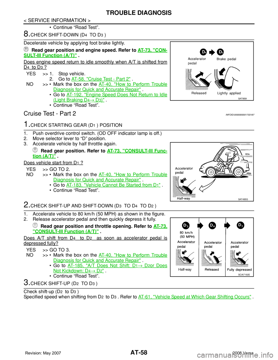
8.CHECK SHIFT-DOWN (D4 TO D3 )
Decelerate vehicle by applying foot brake lightly.
Read gear position and engine speed. Refer to AT-73, "
CON-
SULT-III Function (A/T)" .
Does engine speed return to idle smoothly when A/T is shifted from
D4 to D3 ?
YES >> 1. Stop vehicle.
2. Go to AT-58, "
Cruise Test - Part 2" .
NO >> • Mark the box on the AT-40, "
How to Perform Trouble
Diagnosis for Quick and Accurate Repair" .
•Go to AT-192, "
Engine Speed Does Not Return to Idle
(Light Braking D4→ D3)" .
• Continue “Road Test”.
Cruise Test - Part 2INFOID:0000000001703187
1.CHECK STARTING GEAR (D1 ) POSITION
1. Push overdrive control switch. (OD OFF indicator lamp is off.)
2. Move selector lever to “D” position.
3. Accelerate vehicle by half throttle again.
Read gear position. Refer to AT-73, "
CONSULT-III Func-
tion (A/T)" .
Does vehicle start from D
1 ?
YES >> GO TO 2.
NO >> • Mark the box on the AT-40, "
How to Perform Trouble
Diagnosis for Quick and Accurate Repair" .
•Go to AT-183, "
Vehicle Cannot Be Started from D1" .
• Continue “Road Test”.
2.CHECK SHIFT-UP AND SHIFT-DOWN (D3 TO D4 TO D2 )
1. Accelerate vehicle to 80 km/h (50 MPH) as shown in the figure.
2. Release accelerator pedal and then quickly depress it fully.
Read gear position and throttle opening. Refer to AT-73,
"CONSULT-III Function (A/T)" .
Does A/T shift from D
4 to D2 as soon as accelerator pedal is
depressed fully?
YES >> GO TO 3.
NO >> • Mark the box on the AT-40, "
How to Perform Trouble
Diagnosis for Quick and Accurate Repair" .
•Go to AT-185, "
A/T Does Not Shift: D1→ D2or Does
Not Kickdown: D4→ D2" .
• Continue “Road Test”.
3.CHECK SHIFT-UP (D2 TO D3 )
Check shift-up (D
2 to D3 )
Specified speed when shifting from D
2 to D3 . Refer to AT-61, "Vehicle Speed at Which Gear Shifting Occurs" .
SAT959I
SAT495G
SCIA7192E
Page 218 of 2771
AT-206
< SERVICE INFORMATION >
SHIFT CONTROL SYSTEM
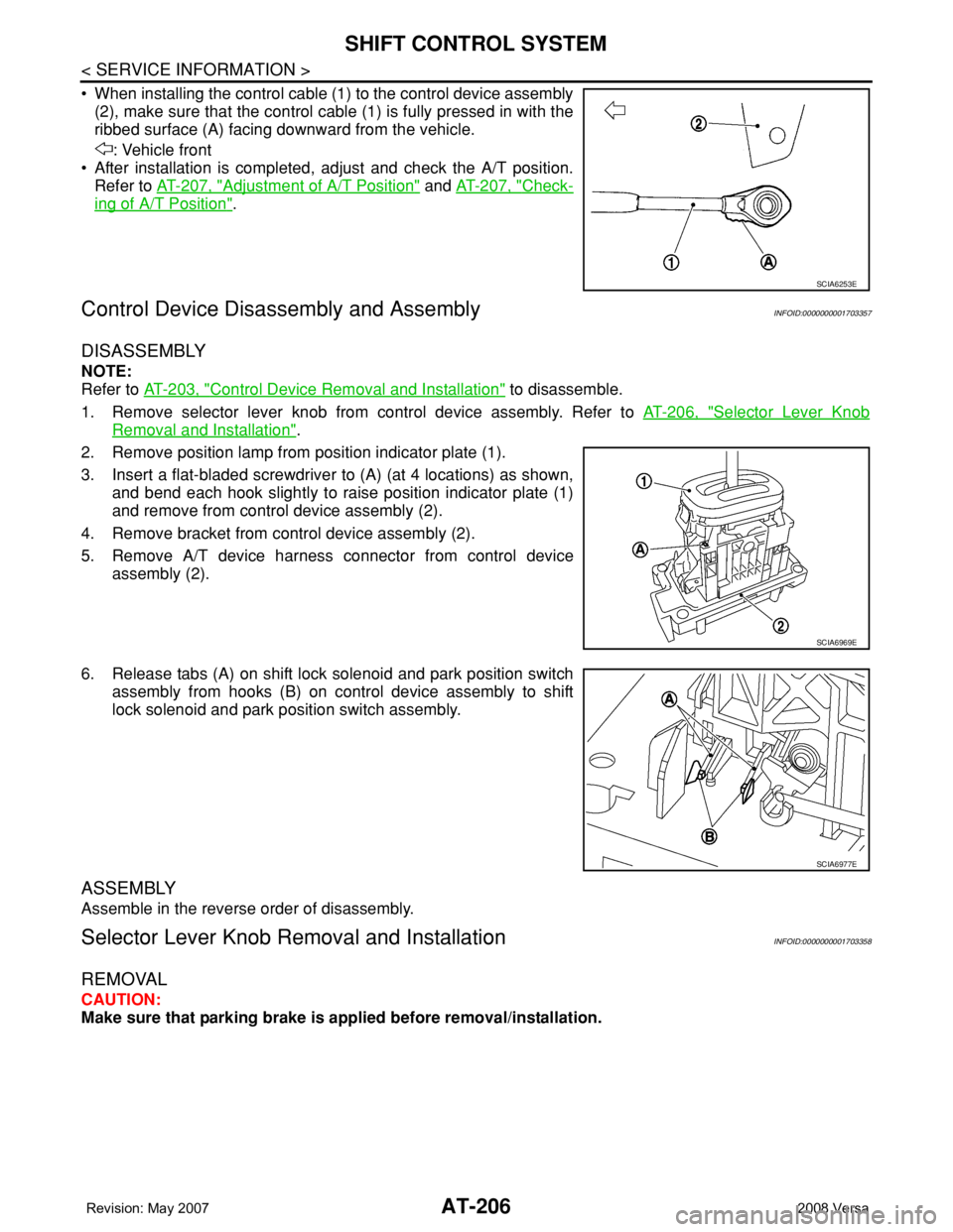
• When installing the control cable (1) to the control device assembly
(2), make sure that the control cable (1) is fully pressed in with the
ribbed surface (A) facing downward from the vehicle.
: Vehicle front
• After installation is completed, adjust and check the A/T position.
Refer to AT-207, "
Adjustment of A/T Position" and AT-207, "Check-
ing of A/T Position".
Control Device Disassembly and AssemblyINFOID:0000000001703357
DISASSEMBLY
NOTE:
Refer to AT-203, "
Control Device Removal and Installation" to disassemble.
1. Remove selector lever knob from control device assembly. Refer to AT-206, "
Selector Lever Knob
Removal and Installation".
2. Remove position lamp from position indicator plate (1).
3. Insert a flat-bladed screwdriver to (A) (at 4 locations) as shown,
and bend each hook slightly to raise position indicator plate (1)
and remove from control device assembly (2).
4. Remove bracket from control device assembly (2).
5. Remove A/T device harness connector from control device
assembly (2).
6. Release tabs (A) on shift lock solenoid and park position switch
assembly from hooks (B) on control device assembly to shift
lock solenoid and park position switch assembly.
ASSEMBLY
Assemble in the reverse order of disassembly.
Selector Lever Knob Removal and InstallationINFOID:0000000001703358
REMOVAL
CAUTION:
Make sure that parking brake is applied before removal/installation.
SCIA6253E
SCIA6969E
SCIA6977E
Page 311 of 2771
REPAIR FOR COMPONENT PARTS
AT-299
< SERVICE INFORMATION >
D
E
F
G
H
I
J
K
L
MA
B
AT
N
O
P
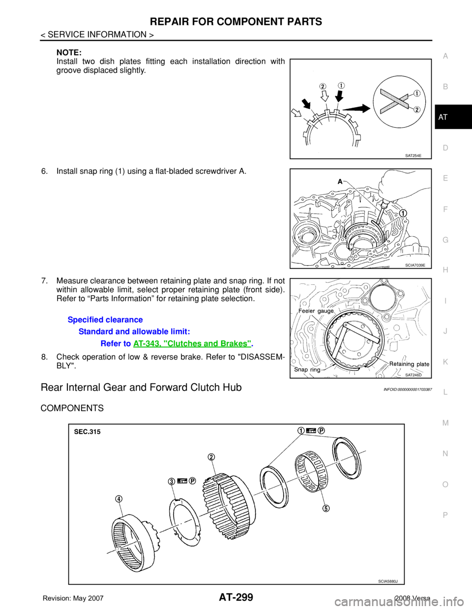
NOTE:
Install two dish plates fitting each installation direction with
groove displaced slightly.
6. Install snap ring (1) using a flat-bladed screwdriver A.
7. Measure clearance between retaining plate and snap ring. If not
within allowable limit, select proper retaining plate (front side).
Refer to “Parts Information” for retaining plate selection.
8. Check operation of low & reverse brake. Refer to "DISASSEM-
BLY".
Rear Internal Gear and Forward Clutch HubINFOID:0000000001703387
COMPONENTS
SAT254E
SCIA7039E
Specified clearance
Standard and allowable limit:
Refer to AT-343, "
Clutches and Brakes".
SAT246D
SCIA5880J
Page 337 of 2771
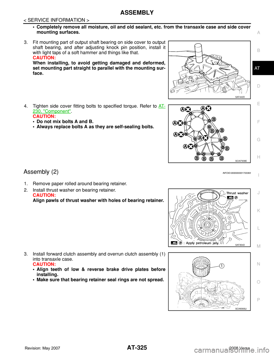
ASSEMBLY
AT-325
< SERVICE INFORMATION >
D
E
F
G
H
I
J
K
L
MA
B
AT
N
O
P
• Completely remove all moisture, oil and old sealant, etc. from the transaxle case and side cover
mounting surfaces.
3. Fit mounting part of output shaft bearing on side cover to output
shaft bearing, and after adjusting knock pin position, install it
with light taps of a soft hammer and things like that.
CAUTION:
When installing, to avoid getting damaged and deformed,
set mounting part straight to parallel with the mounting sur-
face.
4. Tighten side cover fitting bolts to specified torque. Refer to AT-
230, "Component".
CAUTION:
• Do not mix bolts A and B.
• Always replace bolts A as they are self-sealing bolts.
Assembly (2)INFOID:0000000001703393
1. Remove paper rolled around bearing retainer.
2. Install thrust washer on bearing retainer.
CAUTION:
Align pawls of thrust washer with holes of bearing retainer.
3. Install forward clutch assembly and overrun clutch assembly (1)
into transaxle case.
CAUTION:
• Align teeth of low & reverse brake drive plates before
installing.
• Make sure that bearing retainer seal rings are not spread.
SAT442D
SCIA7939E
SAT354D
SCIA5900J
Page 767 of 2771
![NISSAN LATIO 2008 Service Repair Manual BRC-2
< SERVICE INFORMATION >[ABS]
PRECAUTIONS
SERVICE INFORMATION
PRECAUTIONS
Precaution for Supplemental Restraint System (SRS) "AIR BAG" and "SEAT BELT
PRE-TENSIONER"
INFOID:000000 NISSAN LATIO 2008 Service Repair Manual BRC-2
< SERVICE INFORMATION >[ABS]
PRECAUTIONS
SERVICE INFORMATION
PRECAUTIONS
Precaution for Supplemental Restraint System (SRS) "AIR BAG" and "SEAT BELT
PRE-TENSIONER"
INFOID:000000](/img/5/57360/w960_57360-766.png)
BRC-2
< SERVICE INFORMATION >[ABS]
PRECAUTIONS
SERVICE INFORMATION
PRECAUTIONS
Precaution for Supplemental Restraint System (SRS) "AIR BAG" and "SEAT BELT
PRE-TENSIONER"
INFOID:0000000001703818
The Supplemental Restraint System such as “AIR BAG” and “SEAT BELT PRE-TENSIONER”, used along
with a front seat belt, helps to reduce the risk or severity of injury to the driver and front passenger for certain
types of collision. This system includes seat belt switch inputs and dual stage front air bag modules. The SRS
system uses the seat belt switches to determine the front air bag deployment, and may only deploy one front
air bag, depending on the severity of a collision and whether the front occupants are belted or unbelted.
Information necessary to service the system safely is included in the SRS and SB section of this Service Man-
ual.
WARNING:
• To avoid rendering the SRS inoperative, which could increase the risk of personal injury or death in
the event of a collision which would result in air bag inflation, all maintenance must be performed by
an authorized NISSAN/INFINITI dealer.
• Improper maintenance, including incorrect removal and installation of the SRS, can lead to personal
injury caused by unintentional activation of the system. For removal of Spiral Cable and Air Bag
Module, see the SRS section.
• Do not use electrical test equipment on any circuit related to the SRS unless instructed to in this
Service Manual. SRS wiring harnesses can be identified by yellow and/or orange harnesses or har-
ness connectors.
Precaution for Brake SystemINFOID:0000000001703819
CAUTION:
• Refer to MA-10
for recommended brake fluid.
• Never reuse drained brake fluid.
• Be careful not to splash brake fluid on painted areas; it may cause paint damage. If brake fluid is
splashed on painted areas, wash it away with water immediately.
• To clean or wash all parts of master cylinder and disc brake caliper, use clean brake fluid.
• Never use mineral oils such as gasoline or kerosene. They will ruin rubber parts of the hydraulic sys-
tem.
• Use flare nut wrench when removing and installing brake
tube.
• If a brake fluid leak is found, the part must be disassembled
without fail. Then it has to be replaced with a new one if a
defect exists.
• Turn the ignition switch OFF and remove the connector of the
ABS actuator and electric unit (control unit) or the battery ter-
minal before performing the work.
• Always torque brake lines when installing.
• Burnish the brake contact surfaces after refinishing or replac-
ing rotors, after replacing pads, or if a soft pedal occurs at
very low mileage. Refer to BR-28, "
Brake Burnishing Proce-
dure".
WARNING:
• Clean brake pads and shoes with a waste cloth, then wipe with a dust collector.
Precaution for Brake ControlINFOID:0000000001703821
• During ABS operation, the brake pedal may vibrate lightly and a mechanical noise may be heard. This is
normal.
• Just after starting the vehicle, the brake pedal may vibrate or motor operating noises may be heard from
engine compartment. This is normal due to the self check operation.
• Stopping distance may be longer than that of vehicles without ABS when vehicle drives on rough, gravel, or
snow-covered (fresh, deep snow) roads.
SBR686C
Page 770 of 2771
![NISSAN LATIO 2008 Service Repair Manual SYSTEM DESCRIPTION
BRC-5
< SERVICE INFORMATION >[ABS]
C
D
E
G
H
I
J
K
L
MA
B
BRC
N
O
P
SYSTEM DESCRIPTION
System ComponentINFOID:0000000001703825
ABS FunctionINFOID:0000000001703826
• The Anti-Lock NISSAN LATIO 2008 Service Repair Manual SYSTEM DESCRIPTION
BRC-5
< SERVICE INFORMATION >[ABS]
C
D
E
G
H
I
J
K
L
MA
B
BRC
N
O
P
SYSTEM DESCRIPTION
System ComponentINFOID:0000000001703825
ABS FunctionINFOID:0000000001703826
• The Anti-Lock](/img/5/57360/w960_57360-769.png)
SYSTEM DESCRIPTION
BRC-5
< SERVICE INFORMATION >[ABS]
C
D
E
G
H
I
J
K
L
MA
B
BRC
N
O
P
SYSTEM DESCRIPTION
System ComponentINFOID:0000000001703825
ABS FunctionINFOID:0000000001703826
• The Anti-Lock Brake System detects wheel revolution while braking and improves handling stability during
sudden braking by electrically preventing wheel lockup. Maneuverability is also improved for avoiding obsta-
cles during emergency braking.
• If the electrical system malfunctions, the Fail-Safe function is activated, the ABS becomes inoperative and
the ABS warning lamp turns on.
• The electrical system can be diagnosed using CONSULT-III.
• During ABS operation, the brake pedal may vibrate lightly and a mechanical noise may be heard. This is
normal.
• Just after starting the vehicle, the brake pedal may vibrate or motor operating noises may be heard from the
engine compartment. This is normal due to the self check operation.
• Stopping distance may be longer than that of vehicles without ABS when vehicle drives on rough, gravel, or
snow-covered (fresh, deep snow) roads.
EBD FunctionINFOID:0000000001703827
• Electronic Brake Distribution is a function that detects subtle slippages between the front and rear wheels
during braking, and it improves handling stability by electronically controlling the brake fluid pressure which
results in reduced rear wheel slippage.
• If the electrical system malfunctions, the Fail-Safe function is activated, the EBD and ABS become inopera-
tive, and the ABS warning lamp and brake warning lamp are turned on.
• The electrical system can be diagnosed using CONSULT-III.
• During EBD operation, the brake pedal may vibrate lightly and a mechanical noise may be heard. This is
normal.
• Just after starting the vehicle, the brake pedal may vibrate or motor operating noises may be heard from the
engine compartment. This is normal due to the self check operation.
Fail-Safe FunctionINFOID:0000000001703828
CAUTION:
If the Fail-Safe function is activated, perform the Self Diagnosis for ABS system.
ABS/EBD SYSTEM
In case of an electrical malfunction with the ABS, the ABS warning lamp will turn on. In case of an electrical
malfunction with the EBD system, the brake warning lamp and the ABS warning lamp will turn on.
The system will revert to one of the following conditions of the Fail-Safe function.
1. For ABS malfunction, only the EBD is operative and the condition of the vehicle is the same condition of
vehicles without ABS system.
WFIA0118E
Page 847 of 2771

CVT-8
< SERVICE INFORMATION >
PRECAUTIONS
• Be sure to turn the ignition switch OFF and disconnect the battery cable from the negative terminal
before any repair or inspection work. The open/short circuit of related switches, sensors, solenoid
valves, etc. will cause the MIL to light up.
• Be sure to connect and lock the connectors securely after work. A loose (unlocked) connector will
cause the MIL to light up due to an open circuit. (Be sure the connector is free from water, grease,
dirt, bent terminals, etc.)
• Be sure to route and secure the harnesses properly after work. Interference of the harness with a
bracket, etc. may cause the MIL to light up due to a short circuit.
• Be sure to connect rubber tubes properly after work. A misconnected or disconnected rubber tube
may cause the MIL to light up due to a malfunction of the EVAP system or fuel injection system, etc.
• Be sure to erase the unnecessary malfunction information (repairs completed) from the TCM and
ECM before returning the vehicle to the customer.
Service After Replacing TCM and Transaxle AssemblyINFOID:0000000001703427
SERVICE AFTER REPLACING TCM AND TRANSAXLE ASSEMBLY
Perform the applicable service in the following sheet when replacing TCM or transaxle assembly
CAUTION:
• Do not start the engine until the service is completed.
• “A/T C/U POWER SUPPLY [P1701]” may be indicated soon after replacing TCM or transaxle assem-
bly (after erasing the memory at the pattern B). Restart the self-diagnosis after erasing the self-diag-
nosis result. Check that no error is detected.
NOTE:
Old unit means that the unit has been already used for another vehicle.
PATTERN A
1. Shift the selector lever to “P” position after replacing TCM. Turn the ignition switch ON.
2. Check that the shift position indicator in the combination meter turns ON (It indicates approximately 1 or 2
seconds after turning the ignition switch ON.)
• Check the following items if the shift position indicator does not turn ON. Repair or replace the shift posi-
tion indicator if necessary.
- The harness between TCM and ROM ASSY in the transaxle assembly is open or short.
- Cable disconnected, loosen, or bent from the connector housing.
PATTERN B
1. Turn the ignition switch ON after replacing each part.
2. Start engine.
CAUTION:
Do not start the driving.
3. Touch CONSULT-III screen in the order of “START (NISSAN BASED VHCL)”, “TRANSMISSION”, “DATA
MONITOR”, and “MAIN SIGNALS”.
4. Warm up the transaxle assembly until “ATFTEMPCOUNT” indicates 47 [approximately 20°C (68°F)] or
more. Turn the ignition switch OFF.
5. Turn the ignition switch ON.
CAUTION:
Do not start engine.
6. Select “SELF-DIAG RESULTS”.
7. Shift the selector lever to “R” position.
8. Depress slightly the accelerator pedal (Pedal angle: 2/8) while depressing the brake pedal.
9. Perform “ERASE”.
TCM CVT assemblyService pattern
Replace the new unit. Do not replace the unit. "PATTERN A"
Do not replace the unit. Replace the new or old unit.
"PATTERN B"
Replace the old unit.Do not replace the unit.
Replace the new or old unit.
Replace the new unit. Replace the new or old unit. "PATTERN C"