coolant reservoir NISSAN LATIO 2009 Service User Guide
[x] Cancel search | Manufacturer: NISSAN, Model Year: 2009, Model line: LATIO, Model: NISSAN LATIO 2009Pages: 4331, PDF Size: 58.04 MB
Page 929 of 4331
![NISSAN LATIO 2009 Service User Guide ENGINE COOLANT
CO-35
< SERVICE INFORMATION >
[MR18DE] C
D E
F
G H
I
J
K L
M A CO
NP
O
ENGINE COOLANT
Inspection INFOID:0000000004305234
LEVEL CHECK • Check if the reservoir tank engine coolant level](/img/5/57359/w960_57359-928.png "NISSAN LATIO 2009 Service User Guide ENGINE COOLANT
CO-35
< SERVICE INFORMATION >
[MR18DE] C
D E
F
G H
I
J
K L
M A CO
NP
O
ENGINE COOLANT
Inspection INFOID:0000000004305234
LEVEL CHECK • Check if the reservoir tank engine coolant level")
ENGINE COOLANT
CO-35
< SERVICE INFORMATION >
[MR18DE] C
D E
F
G H
I
J
K L
M A CO
NP
O
ENGINE COOLANT
Inspection INFOID:0000000004305234
LEVEL CHECK • Check if the reservoir tank engine coolant level is within the “MIN” to “MAX” range when engine is cool.
• Adjust the engine coolant level as necessary.
CHECKING COOLING SYSTEM FOR LEAKS To check for leaks, apply pressure to the cooling system using suit-
able tool and Tool.
WARNING:
Never remove the radiator cap wh en the engine is hot. Serious
burns could occur from high pressure coolant escaping from
the radiator.
CAUTION:
Higher pressure than specified may cause radiator damage.
Changing Engine Coolant INFOID:0000000004673021
WARNING:
• To avoid being scalded, do not change engine coolant when engine is hot.
• Wrap a thick cloth around radiator cap and carefully remove the cap. First, turn the cap a quarter of a
turn to release built-up pressure. Then turn the cap all the way.
CAUTION:
• Do not spill engine coolant on drive belt.
DRAINING ENGINE COOLANT 1. Open radiator drain plug (1) at the bottom of radiator, and then remove radiator cap.
• Front
When draining all of engine coolant in the system, open
water drain plug on cylinder block. Refer to EM-200 .
CAUTION:
• Perform this step when engine is cold.
• Do not spill engine coolant on drive belt.
2. Remove reservoir tank as necessary, and drain engi ne coolant and clean reservoir tank before installing.
Refer to CO-38, " Component " .
3. Check drained engine coolant for contaminants such as rust, corrosion or discoloration. If contaminated, flush the engine cooling system. SMA412B
Tool number : EG17650301 (J-33984-A)
Testing pressure : 157 kPa (1.6 kg/cm 2
, 23 psi) WBIA0568E
PBIC3799E
Page 930 of 4331
![NISSAN LATIO 2009 Service User Guide CO-36< SERVICE INFORMATION >
[MR18DE]
ENGINE COOLANT
REFILLING ENGINE COOLANT
1. Install the radiator drain plug. Install the reservoir tank and cylinder block drain plug, if removed for a total
syst](/img/5/57359/w960_57359-929.png "NISSAN LATIO 2009 Service User Guide CO-36< SERVICE INFORMATION >
[MR18DE]
ENGINE COOLANT
REFILLING ENGINE COOLANT
1. Install the radiator drain plug. Install the reservoir tank and cylinder block drain plug, if removed for a total
syst")
CO-36< SERVICE INFORMATION >
[MR18DE]
ENGINE COOLANT
REFILLING ENGINE COOLANT
1. Install the radiator drain plug. Install the reservoir tank and cylinder block drain plug, if removed for a total
system drain or for engine removal or repair.
• The radiator must be complete ly empty of coolant and water.
• Apply sealant to the threads of the cylinder bl ock drain plugs. Use Genuine High Performance
Thread Sealant or equivalent. Refer to GI-42, " Recommended Chemical Product and Sealant " .
2. If disconnected, reattach the upper radiator hose at the engine side.
3. Set the vehicle heater controls to the full HOT and heat er ON position. Turn the vehicle ignition ON with
the engine OFF as necessary to activate the heater mode.
4. Install the Tool by installing the radiator cap adapter onto the radiator neck opening. Then attach the gauge body assembly
with the refill tube and the venturi assembly to the radiator cap
adapter.
5. Insert the refill hose into the coolant mixture container that is placed at floor level. Make sure the ball valve is in the closed
position.
• Use Genuine NISSAN Long Life Anti-freeze coolant or
equivalent, mixed with distil led water or demineralized
water.
Refer to MA-15, " Anti-freeze Coolant Mixture Ratio " .
6. Install an air hose to the venturi assembly, the air pressure must be within specification.
CAUTION:
The compressed air supply must be equipped with an air dryer.
7. The vacuum gauge will begin to rise and there will be an audible hissing noise. During this process open the ball valve on the refill hose slightly. Coolant will be vi sible rising in the refill hose. Once the refill hose is
full of coolant, close the ball valve. This will purge any air trapped in the refill hose.
8. Continue to draw the vacuum until the gauge reaches 28 inches of vacuum. The gauge may not reach 28 inches in high altitude
locations, use the vacuum specifications based on the altitude
above sea level.
9. When the vacuum gauge has reached the specifi ed amount, disconnect the air hose and wait 20 seconds
to see if the system loses any vacuum. If the vacuum level drops, perform any necessary repairs to the
system and repeat steps 6 - 8 to bring the vacuum to the specified amount. Recheck for any leaks.
Radiator drain plug : Refer to
CO-38, " Component " .
Cylinder block drain plug : Refer to EM-200, " Disassembly and Assembly " .
Tool number : KV991J0070 (J-45695)
Engine coolant capacity
(with reservoir tank) : Refer to
MA-14, " Fluids
and Lubricants " .
Compressed air
supply pressure : 5.7 - 8.5 kPa (5.6 - 8.4 kg/cm
2
,
80 - 120 psi) LLIA0058E
Altitude above sea level Vacuum gauge reading
0 - 100 m (328 ft) : 28 inches of vacuum
300 m (984 ft) : 27 inches of vacuum
500 m (1,641 ft) : 26 inches of vacuum
1,000 m (3,281 ft) : 24 - 25 inches of vacuum LLIA0057E
Page 931 of 4331
CO
NP
O
10. Place the coolant container (with the refill hose inserted)
at the same level as the top of the radiator. Then
open the ball valve on the refill hose so the coolant will be drawn up to fill the cooling system. The cooling
system is full when the vacuum gauge reads zero.
CAUTION:
Do not allow the coolant container to get too low when filling, to avoid air from being drawn into
the cooling system.
11. Remove the Tool from the radiator neck opening.
12. Fill the cooling system reservoir tank to the specif ied level and install the radiator cap. Run the engine to
warm up the cooling system and top up the system as necessary.
FLUSHING COOLING SYSTEM 1. Install reservoir tank if removed. Refer to CO-38, " Component " .
2. Install radiator drain plug. •If water drain plug on cylinder block is removed, close and tighten it. Refer to EM-200, " Disas-
sembly and Assembly " .
CAUTION:
Be sure to clean radiator drain plug and install with new O-ring. Refer to CO-38, " Component " .
3. Fill radiator and reservoir tank with water and reinstall radiator cap.
4. Run engine and warm it up to normal operating temperature.
5. Rev engine two or three times under no-load.
6. Stop engine and wait until it cools down.
7. Drain water from the cooling system.
8. Repeat steps 1 through 7 until clear water begins to drain from radiator.
Page 933 of 4331
![NISSAN LATIO 2009 Service User Guide RADIATOR
CO-39
< SERVICE INFORMATION >
[MR18DE] C
D E
F
G H
I
J
K L
M A CO
NP
O
Do not remove radiator cap when the engine is
hot. Serious burns could occur from high-pressure
engine c](/img/5/57359/w960_57359-932.png "NISSAN LATIO 2009 Service User Guide RADIATOR
CO-39
< SERVICE INFORMATION >
[MR18DE] C
D E
F
G H
I
J
K L
M A CO
NP
O
Do not remove radiator cap when the engine is
hot. Serious burns could occur from high-pressure
engine c")
RADIATOR
CO-39
< SERVICE INFORMATION >
[MR18DE] C
D E
F
G H
I
J
K L
M A CO
NP
O
Do not remove radiator cap when the engine is
hot. Serious burns could occur from high-pressure
engine coolant escaping from radiator. Wrap a thick cl oth around the cap. Slowly turn it a quarter of a
turn to release built-up pressure. Carefully remove radiator cap by turning it all the way.
REMOVAL 1. Drain engine coolant from radiator. Refer to CO-35, " Changing Engine Coolant " .
CAUTION:
• Perform this step when engine is cold.
• Do not spill engine coolant on drive belt.
2. Remove engine undercover.
3. Remove air duct (inlet). Refer to EM-139 .
4. Remove reservoir tank as follows:
a. Disconnect reservoir tank hose.
b. Release the tab (A) in the direction shown by the arrow ( ).
c. Lift up while removing the reservoir tank hose, and remove it.
5. Disconnect harness connector from fan motor, and move harness aside.
6. Disconnect CVT or A/T fluid cooler hoses if equipped. • Install plug to avoid leakage of CVT or A/T fluid if equipped.
7. Remove radiator hoses (upper and lower).
8. Remove radiator core support cover. Refer to BL-19 .
9. Remove radiator core support (upper) bolts, bolts of stationary part on the radiator core support side and clip. Lift radiator from
radiator (upper) mount part of radiator core support (upper) (2).
10. Move radiator assembly (1) to the rearward direction of vehicle, and then lift it upward to remove.
CAUTION:
Do not damage or scratch A/C condenser if equipped and
radiator core when removing.
INSTALLATION Installation is in the reverse order of removal.
CAUTION:
Do not damage or scratch A/C condenser if eq uipped and radiator core when installing.
INSPECTION AFTER INSTALLATION • Check for leaks of engine coolant. Refer to CO-35, " Inspection " .
• Start and warm up engine. Visually check for leaks of engine coolant and CVT or A/T fluid if equipped. Refer
to CVT-196 or
AT-17 . PBIC3800E
PBIC3805E
Page 936 of 4331
Changing Engine Coolant " .
CAUTION:
• Perform this step when engine is cold.
• Do not spill engine coolant on drive belt.
2. Remove air duct (inlet). Refer to EM-139, " Component " .
3. Remove reservoir tank. Refer to CO-38, " Component " .
4. Disconnect radiator hose (upper) at radiator side. Refer to CO-38, " Component " .
5. Disconnect harness connectors from fan motor, and move harness aside.
6. Remove cooling fan assembly. CAUTION:
Be careful not to damage or scratch the radiator core.
INSTALLATION
Installation is in the reverse order of removal.
• Cooling fans are controlled by ECM. For details, refer to EC-886, " System Description " .
CAUTION:
Be careful not to damage or scratch the radiator core.
Disassembly and Assembly INFOID:0000000004305243
DISASSEMBLY
1. Remove cooling fan from fan motor.
2. Remove fan motor from fan shroud.
INSPECTION AFTER DISASSEMBLY
Inspect cooling fan for crack or unusual bend.
• If anything is found, replace cooling fan.
ASSEMBLY
Assembly is in the reverse order of disassembly.
Page 937 of 4331
CO
NP
O
WATER PUMP
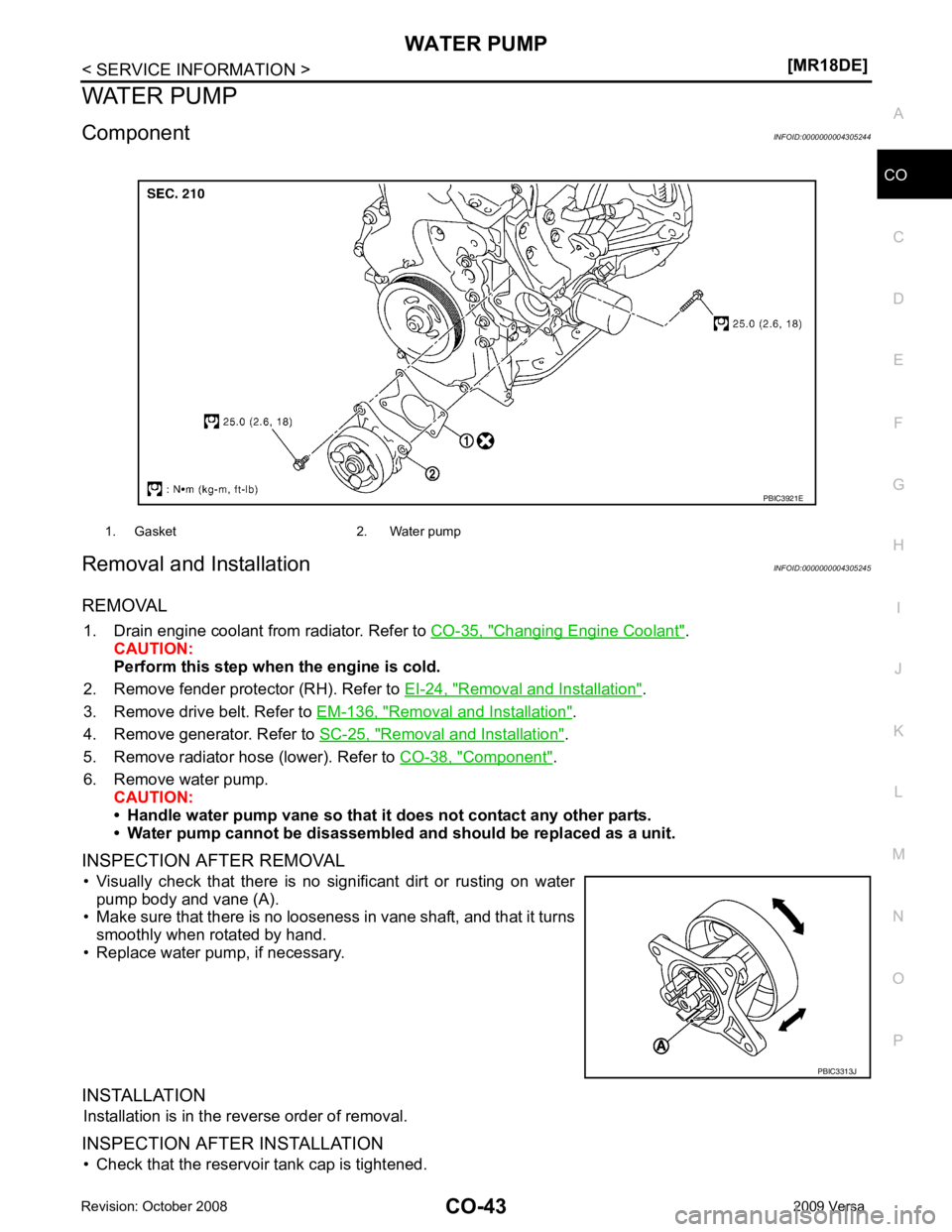
Component INFOID:0000000004305244
Removal and Installation INFOID:0000000004305245
REMOVAL 1. Drain engine coolant from radiator. Refer to CO-35, " Changing Engine Coolant " .
CAUTION:
Perform this step when the engine is cold.
2. Remove fender protector (RH). Refer to EI-24, " Removal and Installation " .
3. Remove drive belt. Refer to EM-136, " Removal and Installation " .
4. Remove generator. Refer to SC-25, " Removal and Installation " .
5. Remove radiator hose (lower). Refer to CO-38, " Component " .
6. Remove water pump. CAUTION:
• Handle water pump vane so that it does not contact any other parts.
• Water pump cannot be disassembled and should be replaced as a unit.
INSPECTION AFTER REMOVAL • Visually check that there is no significant dirt or rusting on water pump body and vane (A).
• Make sure that there is no looseness in vane shaft, and that it turns
smoothly when rotated by hand.
• Replace water pump, if necessary.
INSTALLATION Installation is in the reverse order of removal.
INSPECTION AFTER INSTALLATION • Check that the reservoir tank cap is tightened. 1. Gasket 2. Water pump
PBIC3313J
Page 1725 of 4331
EC
NP
O
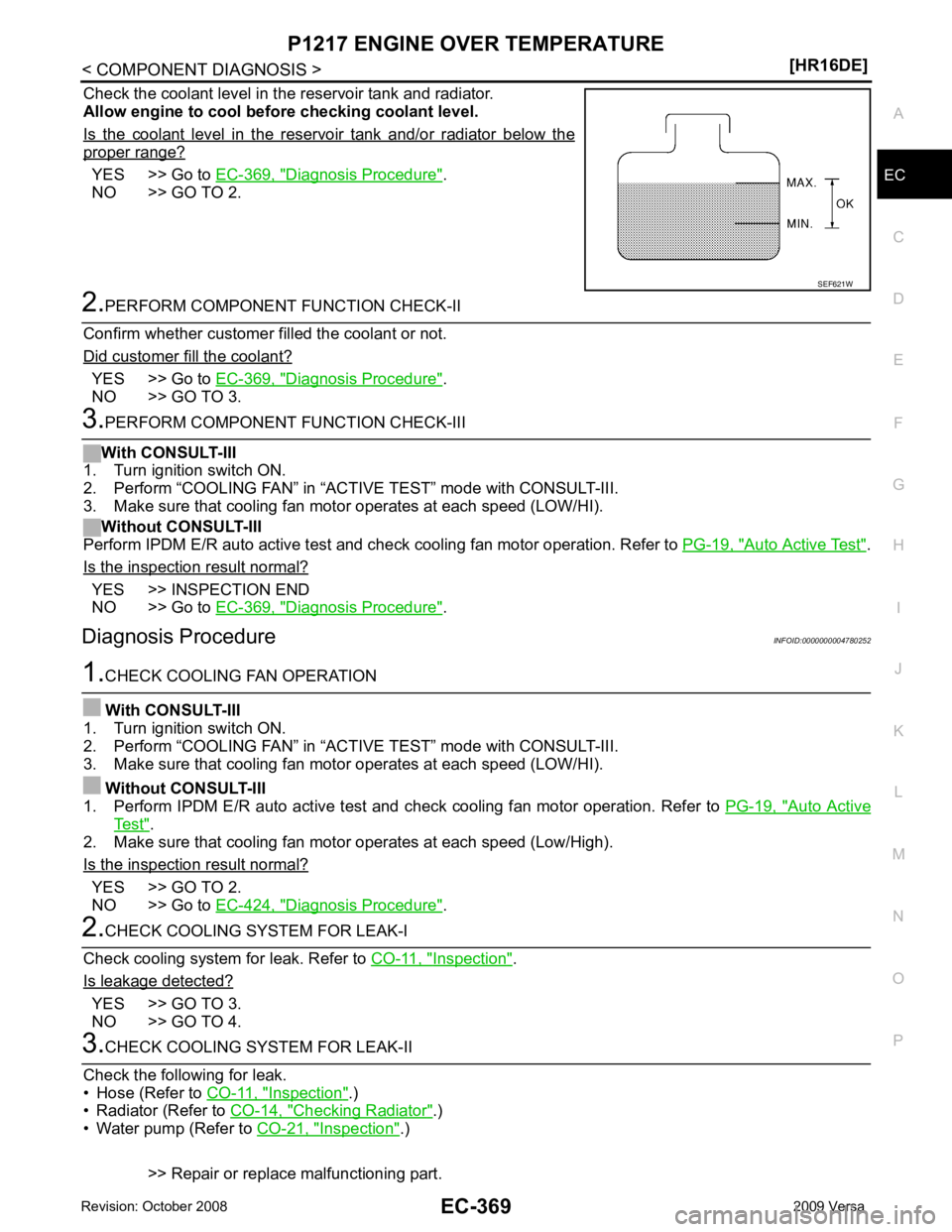
Check the coolant level in the reservoir tank and radiator.
Allow engine to cool befo re checking coolant level.
Is the coolant level in the reservoir tank and/or radiator below the proper range?
YES >> Go to
EC-369, " Diagnosis Procedure " .
NO >> GO TO 2. YES >> Go to
EC-369, " Diagnosis Procedure " .
NO >> GO TO 3. Auto Active Test " .
Is the inspection result normal? YES >> INSPECTION END
NO >> Go to EC-369, " Diagnosis Procedure " .
Diagnosis Procedure INFOID:0000000004780252 Auto Active
Test " .
2. Make sure that cooling fan motor operates at each speed (Low/High).
Is the inspection result normal? YES >> GO TO 2.
NO >> Go to EC-424, " Diagnosis Procedure " .
Inspection " .
Is leakage detected? YES >> GO TO 3.
NO >> GO TO 4. Inspection " .)
• Radiator (Refer to CO-14, " Checking Radiator " .)
• Water pump (Refer to CO-21, " Inspection " .)
>> Repair or replace malfunctioning part.
Page 1726 of 4331
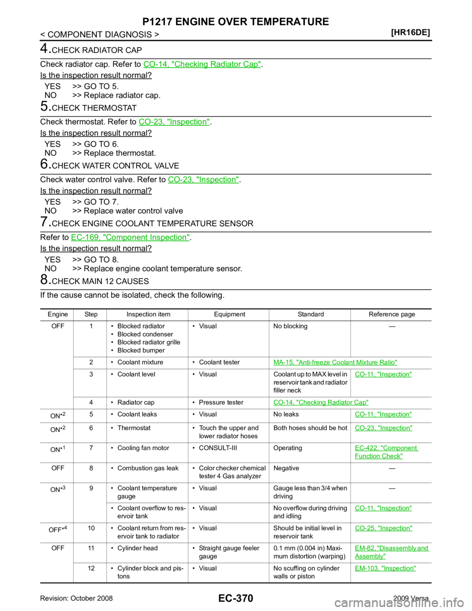
Checking Radiator Cap " .
Is the inspection result normal? YES >> GO TO 5.
NO >> Replace radiator cap. Inspection " .
Is the inspection result normal? YES >> GO TO 6.
NO >> Replace thermostat. Inspection " .
Is the inspection result normal? YES >> GO TO 7.
NO >> Replace water control valve Component Inspection " .
Is the inspection result normal? YES >> GO TO 8.
NO >> Replace engine coolant temperature sensor. Anti-freeze Coolant Mixture Ratio "
3 • Coolant level • Visual Coolant up to MAX level in
reservoir tank and radiator
filler neck CO-11, " Inspection "
4 • Radiator cap • Pressure tester
CO-14, " Checking Radiator Cap "
ON*
2
5 • Coolant leaks • Visual No leaks CO-11, " Inspection "
ON*
2
6 • Thermostat • Touch the upper and
lower radiator hosesBoth hoses should be hot
CO-23, " Inspection "
ON*
1
7 • Cooling fan motor • CONSULT-III Operating EC-422, " Component
Function Check "
OFF 8 • Combustion gas leak • Color checker chemical
tester 4 Gas analyzerNegative —
ON* 3
9 • Coolant temperature
gauge • Visual Gauge less than 3/4 when
driving —
• Coolant overflow to res- ervoir tank • Visual No overflow during driving
and idling CO-11, " Inspection "
OFF*
4
10 • Coolant return from res-
ervoir tank to radiator • Visual Should be initial level in
reservoir tank CO-25, " Inspection "
OFF 11 • Cylinder head • Straight gauge feeler
gauge0.1 mm (0.004 in) Maxi-
mum distortion (warping) EM-82, " Disassembly and
Assembly "
12 • Cylinder block and pis-
tons • Visual No scuffing on cylinder
walls or piston EM-103, " Inspection "
Page 2243 of 4331
EC
NP
O
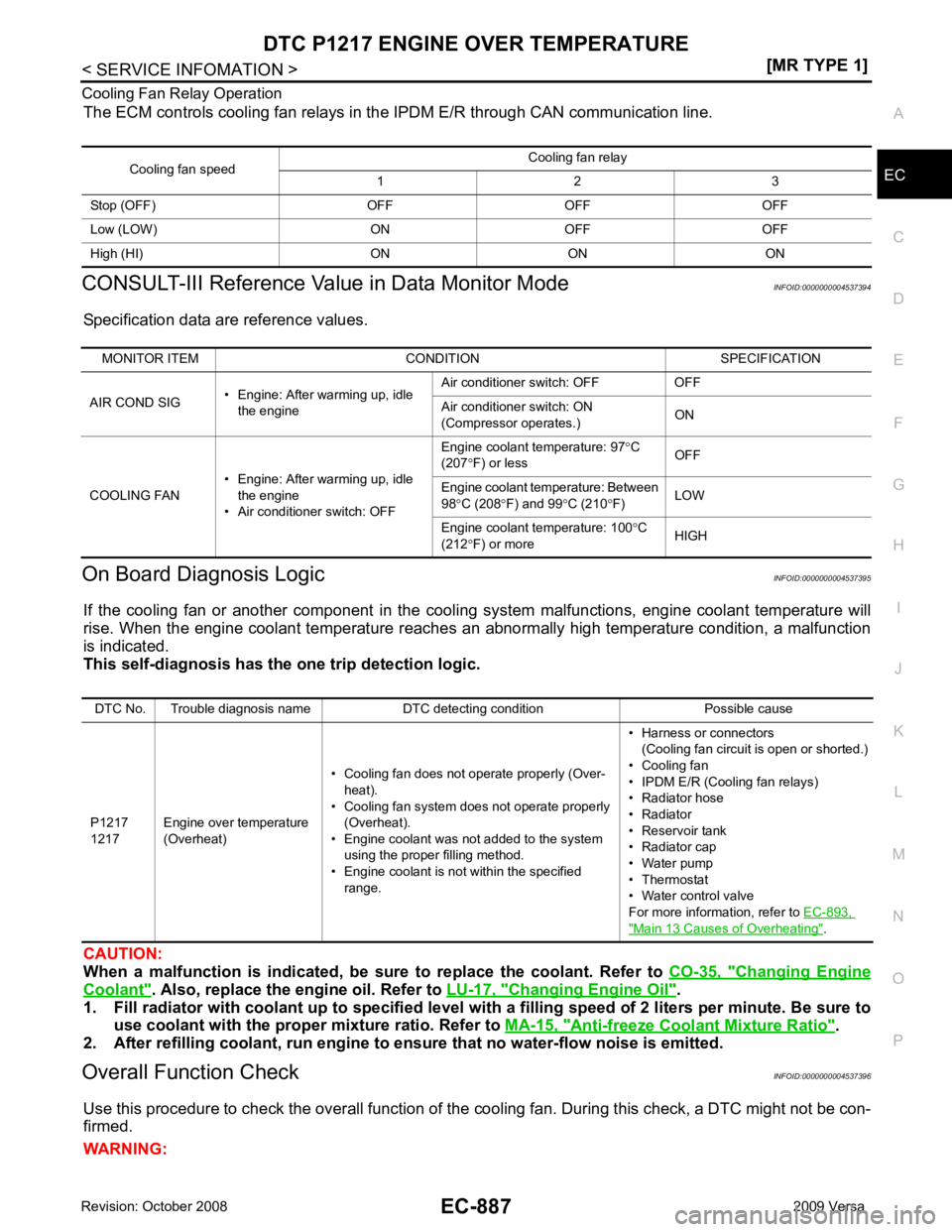
Cooling Fan Relay Operation
The ECM controls cooling fan relays in the IPDM E/R through CAN communication line.
CONSULT-III Reference Val ue in Data Monitor Mode INFOID:0000000004537394
Specification data are reference values.
On Board Diagnosis Logic INFOID:0000000004537395
If the cooling fan or another component in the cooli ng system malfunctions, engine coolant temperature will
rise. When the engine coolant temperature reaches an abnormally high temperature condition, a malfunction
is indicated.
This self-diagnosis has the on e trip detection logic.
CAUTION:
When a malfunction is in dicated, be sure to replace the coolant. Refer to CO-35, " Changing Engine
Coolant " . Also, replace the engine oil. Refer to
LU-17, " Changing Engine Oil " .
1. Fill radiator with coolant up to specified level with a filling speed of 2 liters per minute. Be sure to
use coolant with the proper mixture ratio. Refer to MA-15, " Anti-freeze Coolant Mixture Ratio " .
2. After refilling coolant, run engine to ensure that no water-flow noise is emitted.
Overall Function Check INFOID:0000000004537396
Use this procedure to check the overall function of the cooling fan. During this check, a DTC might not be con-
firmed.
WARNING: Cooling fan speed
Cooling fan relay
1 2 3
Stop (OFF) OFF OFF OFF
Low (LOW) ON OFF OFF
High (HI) ON ON ON MONITOR ITEM CONDITION SPECIFICATION
AIR COND SIG • Engine: After warming up, idle
the engine Air conditioner switch: OFF OFF
Air conditioner switch: ON
(Compressor operates.) ON
COOLING FAN • Engine: After warming up, idle
the engine
• Air conditioner switch: OFF Engine coolant temperature: 97
°C
(207 °F) or less OFF
Engine coolant temperature: Between
98 °C (208 °F) and 99 °C (210 °F) LOW
Engine coolant temperature: 100 °C
(212 °F) or more HIGHDTC No. Trouble diagnosis name DTC detecting condition Possible cause
P1217
1217 Engine over temperature
(Overheat) • Cooling fan does not operate properly (Over-
heat).
• Cooling fan system does not operate properly (Overheat).
• Engine coolant was not added to the system using the proper filling method.
• Engine coolant is not within the specified
range. • Harness or connectors
(Cooling fan circuit is open or shorted.)
• Cooling fan
• IPDM E/R (Cooling fan relays)
• Radiator hose
• Radiator
• Reservoir tank
• Radiator cap
• Water pump
• Thermostat
• Water control valve
For more information, refer to EC-893, " Main 13 Causes of Overheating " .
Page 2244 of 4331
![NISSAN LATIO 2009 Service User Guide EC-888< SERVICE INFOMATION >
[MR TYPE 1]
DTC P1217 ENGINE
OVER TEMPERATURE
Never remove the radiator cap when the engine is hot. Serious burns could be caused by high pres-
sure flui](/img/5/57359/w960_57359-2243.png "NISSAN LATIO 2009 Service User Guide EC-888< SERVICE INFOMATION >
[MR TYPE 1]
DTC P1217 ENGINE
OVER TEMPERATURE
Never remove the radiator cap when the engine is hot. Serious burns could be caused by high pres-
sure flui")
EC-888< SERVICE INFOMATION >
[MR TYPE 1]
DTC P1217 ENGINE
OVER TEMPERATURE
Never remove the radiator cap when the engine is hot. Serious burns could be caused by high pres-
sure fluid escaping from the reser voir tank or the radiator.
Wrap a thick cloth around cap. Carefully remove the cap by turning it a quarter turn to allow built-up
pressure to escape. Then turn the cap all the way off.
WITH CONSULT-III
1. Check the coolant level in the reservoir tank and radiator. Allow engine to cool before checking coolant level.
If the coolant level in the reservoir tank and/or radiator is below
the proper range, skip the following steps and go to EC-890," Diagnosis Procedure " or
EC-890, " Diagnosis Procedure " .
2. Confirm whether customer filled the coolant or not. If customer
filled the coolant, skip the following steps and go to EC-890," Diagnosis Procedure " or
EC-890, " Diagnosis Procedure " .
3. Turn ignition switch ON.
4. Perform “COOLING FAN” in “ACTIVE TEST” mode with CON- SULT-III.
5. If the results are NG, go to EC-890, " Diagnosis Procedure " or
EC-890, " Diagnosis Procedure " .
WITH GST
1. Check the coolant level in the reservoir tank and radiator. Allow engine to cool before checking coolant level.
If the coolant level in the reservoir tank and/or radiator is below
the proper range, skip the following steps and go to EC-890," Diagnosis Procedure " .
2. Confirm whether customer filled the coolant or not. If customer
filled the coolant, skip the following steps and go to EC-890," Diagnosis Procedure " .
3. Perform IPDM/ER auto active te st and check cooling fan motor
operation. Refer to PG-19, " Auto Active Test " .
4. If NG, go to EC-890, " Diagnosis Procedure " . SEF621W
SEF621W