tow NISSAN LATIO 2009 Service Owner's Manual
[x] Cancel search | Manufacturer: NISSAN, Model Year: 2009, Model line: LATIO, Model: NISSAN LATIO 2009Pages: 4331, PDF Size: 58.04 MB
Page 3046 of 4331
EM
NP
O
CAUTION:
Dimension L1 of journal No. 3 is the distance fr om the housing base end surface (bulk) (not the
distance from the thrust bearing mounting end surface).
4. Install signal plate to crankshaft if removed.
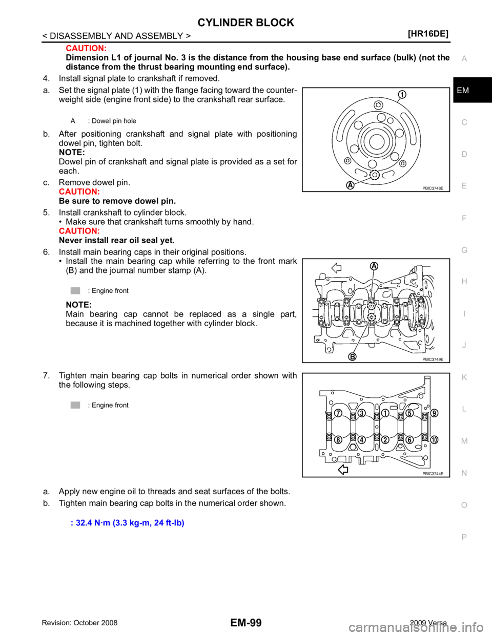
a. Set the signal plate (1) with the flange facing toward the counter- weight side (engine front side) to the crankshaft rear surface.
b. After positioning crankshaft and signal plate with positioning dowel pin, tighten bolt.
NOTE:
Dowel pin of crankshaft and signal plate is provided as a set for
each.
c. Remove dowel pin. CAUTION:
Be sure to remove dowel pin.
5. Install crankshaft to cylinder block. • Make sure that crankshaft turns smoothly by hand.
CAUTION:
Never install rear oil seal yet.
6. Install main bearing caps in their original positions. • Install the main bearing cap while referring to the front mark(B) and the journal number stamp (A).
NOTE:
Main bearing cap cannot be replaced as a single part,
because it is machined together with cylinder block.
7. Tighten main bearing cap bolts in numerical order shown with the following steps.
a. Apply new engine oil to threads and seat surfaces of the bolts.
b. Tighten main bearing cap bolts in the numerical order shown. A : Dowel pin hole
: Engine front PBIC3749E
Page 3050 of 4331
![NISSAN LATIO 2009 Service Owners Manual CYLINDER BLOCK
EM-103
< DISASSEMBLY AND ASSEMBLY >
[HR16DE] C
D E
F
G H
I
J
K L
M A EM
NP
O
18. Install knock sensor (1).
• Install connectors so that they are positioned towards the rearof the engi](/img/5/57359/w960_57359-3049.png "NISSAN LATIO 2009 Service Owners Manual CYLINDER BLOCK
EM-103
< DISASSEMBLY AND ASSEMBLY >
[HR16DE] C
D E
F
G H
I
J
K L
M A EM
NP
O
18. Install knock sensor (1).
• Install connectors so that they are positioned towards the rearof the engi")
CYLINDER BLOCK
EM-103
< DISASSEMBLY AND ASSEMBLY >
[HR16DE] C
D E
F
G H
I
J
K L
M A EM
NP
O
18. Install knock sensor (1).
• Install connectors so that they are positioned towards the rearof the engine.
CAUTION:
• Never tighten bolt while holding the connector.
• If any impact by dropping is applied to knock sensor,
replace it with a new one.
NOTE:
• Make sure that there is no foreign material on the cylinder block mating surface and the back surface of knock sensor.
• Make sure that knock sensor does not interfere with other parts.
19. Install crankshaft position sensor (POS) and cover. • Tighten bolts with it seated completely.
20. For the oil level gauge guide (1), fix the position (B) shown to the water inlet clip (A) after inserting to the cylinder block side.
21. Assembly is in the reverse order of disassembly after this step.
Inspection INFOID:0000000004784318
CRANKSHAFT END PLAY • Measure the clearance between thrust bearings and crankshaft arm when crankshaft is moved fully forward or backward with a dial
indicator (A).
• If the measured value exceeds the limit, replace thrust bearings, and measure again. If it still exceeds the limit, replace crankshaft
also.
CONNECTING ROD SIDE CLEARANCE • Measure the side clearance between connecting rod and crank- shaft arm with a feeler gauge (A).
• If the measured value exceeds the limit, replace connecting rod, and measure again. If it still exc eeds the standard, replace crank-
shaft also.
PISTON TO PISTON PIN OIL CLEARANCE
Piston Pin Hole Diameter : Engine front
PBIC3754E
PBIC3755E
Standard and Limit : Refer to
EM-121, " Cylinder Block " .
PBIC3762E
Standard : Refer to
EM-121, " Cylinder Block " .
PBIC3763E
Page 3115 of 4331
![NISSAN LATIO 2009 Service Owners Manual EM-168< SERVICE INFORMATION >
[MR18DE]
TIMING CHAIN
• Install front oil seal (2) using a suitable tool with outer diameter 57 mm (2.24 in) and inner diameter 45 mm (1.77 in) (A) to the
dimension sho](/img/5/57359/w960_57359-3114.png "NISSAN LATIO 2009 Service Owners Manual EM-168< SERVICE INFORMATION >
[MR18DE]
TIMING CHAIN
• Install front oil seal (2) using a suitable tool with outer diameter 57 mm (2.24 in) and inner diameter 45 mm (1.77 in) (A) to the
dimension sho")
EM-168< SERVICE INFORMATION >
[MR18DE]
TIMING CHAIN
• Install front oil seal (2) using a suitable tool with outer diameter 57 mm (2.24 in) and inner diameter 45 mm (1.77 in) (A) to the
dimension shown.
CAUTION:
• Be careful not to damage front cover and crankshaft.
• Press-fit oil seal straight to avoid causing burrs or tilting.
• Never touch grease applied onto oil seal lip.
12. Install new O-ring to cylinder block. CAUTION:
Be sure O-rings are aligned properly.
13. Apply the sealant without breaks to the specified location using Tool.
Use Genuine Silicone RTV Seal ant or equivalent. Refer to
GI-42, " Recommended Chemical
Product and Sealant " .
14. Make sure that matching marks of timing chain and each sprocket are still aligned. CAUTION:
• Make sure O-ring on cylinder block is correctly installed.
• Be careful not to damage front oil seal by interference with front end of crankshaft.
1 : Front cover
: Engine front
Within 0.3 mm (0.012 in) toward engine front
Within 0.5 mm (0.020 in) toward engine rear PBIC3729E
Tool number WS39930000 ( – )
A : Liquid gasket application area
B : Liquid gasket
: Engine outside PBIC3959E
Page 3130 of 4331
![NISSAN LATIO 2009 Service Owners Manual OIL SEAL
EM-183
< SERVICE INFORMATION >
[MR18DE] C
D E
F
G H
I
J
K L
M A EM
NP
O
• Drive belt; Refer to
EM-136, " Component " .
• Crankshaft pulley; Refer to EM-160, " Component " .
2. Remove fr](/img/5/57359/w960_57359-3129.png "NISSAN LATIO 2009 Service Owners Manual OIL SEAL
EM-183
< SERVICE INFORMATION >
[MR18DE] C
D E
F
G H
I
J
K L
M A EM
NP
O
• Drive belt; Refer to
EM-136, \" Component \" .
• Crankshaft pulley; Refer to EM-160, \" Component \" .
2. Remove fr")
OIL SEAL
EM-183
< SERVICE INFORMATION >
[MR18DE] C
D E
F
G H
I
J
K L
M A EM
NP
O
• Drive belt; Refer to
EM-136, " Component " .
• Crankshaft pulley; Refer to EM-160, " Component " .
2. Remove front oil seal using a suitable tool. CAUTION:
Be careful not to damage front cover and crankshaft.
INSTALLATION 1. Apply new engine oil to new front oil seal joint surface and seal lip.
2. Install front oil seal so that each seal lip is oriented as shown.
• Install front oil seal (2) using a suitable tool with outer diameter57 mm (2.24 in) and inner diameter 45 mm (1.77 in) (A) to the
dimension as shown.
CAUTION:
• Be careful not to damage front cover and crankshaft.
• Press-fit oil seal straight to avoid causing burrs or tilting.
• Do not touch grease applied on oil seal lip.
3. Installation of the remaining components is in the reverse order of removal.
Removal and Installation of Rear Oil Seal INFOID:0000000004307149
REMOVAL 1. Remove transaxle assembly. Refer to MT-58 (M/T models),
AT-232 (A/T models),
CVT-182 or
CVT-354 (CVT models).
2. Remove clutch cover and clutch disk (M/T models). Refer to CL-15 .
3. Remove drive plate (A/T or CVT models) or flywheel (M/T models). Refer to EM-199, " Component " .
4. Remove rear oil seal with a suitable tool. CAUTION:
Be careful not to damage crankshaft and cylinder block.
INSTALLATION 1. Apply the liquid gasket lightly to entire outside area of new rear oil seal. Use Genuine Silicone RTV Seal ant or equivalent. Refer to GI-42, " Recommended Chemical Prod-
uct and Sealant " .
A : Dust seal lip
B : Oil seal lip
: Engine front
: Engine rear PBIC3485J
1 : Front cover
: Engine front
Within 0.3 mm (0.012 in) toward engine front
Within 0.5 mm (0.020 in) toward engine rear PBIC3729E
Page 3254 of 4331
GI
SECTION GI
N
O P
CONTENTS
GENERAL INFORMATION
SERVICE INFORMATION .. ..........................2
PRECAUTIONS .............................................. .....2
Description .......................................................... ......2
Precaution for Supplemental Restraint System
(SRS) "AIR BAG" and "SEAT BELT PRE-TEN-
SIONER" ............................................................. ......
2
Precaution Necessary fo r Steering Wheel Rota-
tion After Battery Disconnect ............................... ......
2
General Precaution ............................................. ......3
Precaution for Three Way Catalyst ..................... ......4
Precaution for Fuel (Unleaded Regular Gasoline
Recommended) ................................................... ......
4
Precaution for Multiport Fuel Injection System or
Engine Control System ....................................... ......
5
Precaution for Hoses ........................................... ......5
Precaution for Engine Oils .................................. ......6
Precaution for Air Conditioning ........................... ......6
HOW TO USE THIS MANUAL ....................... .....7
Description .......................................................... ......7
Terms .................................................................. ......7
Units .................................................................... ......7
Contents .............................................................. ......7
Relation between Illustrations and Descriptions . ......8
Component .......................................................... ......8
How to Follow Trouble Diagnosis ........................ ......9
How to Read Wiring Diagr am ..................................13
Abbreviations ...................................................... ....20
SERVICE INFORMATION FOR ELECTRICAL
INCIDENT ....................................................... ....
22
How to Check Terminal ...........................................22 How to Perform Efficient Diagnosis for an Electri-
cal Incident .......................................................... ....
25
Control Units and Electrical Parts ........................ ....32
CONSULT-III CHECKING SYSTEM ................. 35
Description ........................................................... ....35
Function and System Application ........................ ....35
CONSULT-III Data Link Connector (DLC) Circuit ....36
LIFTING POINT ................................................. 38
Special Service Tool ............................................ ....38
Garage Jack and Safety Stand and 2-Pole Lift ... ....38
Board-On Lift ....................................................... ....39
TOW TRUCK TOWING ..................................... 40
Tow Truck Towing ............................................... ....40
Vehicle Recovery (Freeing a Stuck Vehicle) ....... ....40
TIGHTENING TORQUE OF STANDARD
BOLTS ............................................................... 41
Tightening Torque Table ..................................... ....41
RECOMMENDED CHEMICAL PRODUCTS
AND SEALANTS ............................................... 42
Recommended Chemical Product and Sealant ... ....42
IDENTIFICATION INFORMATION .................... 43
Model Variation .................................................... ....43
Dimensions .......................................................... ....46
Wheels & Tires .................................................... ....46
TERMINOLOGY ................................................ 47
SAE J1930 Terminology List ............................... ....47
Page 3348 of 4331
GW
N
O P
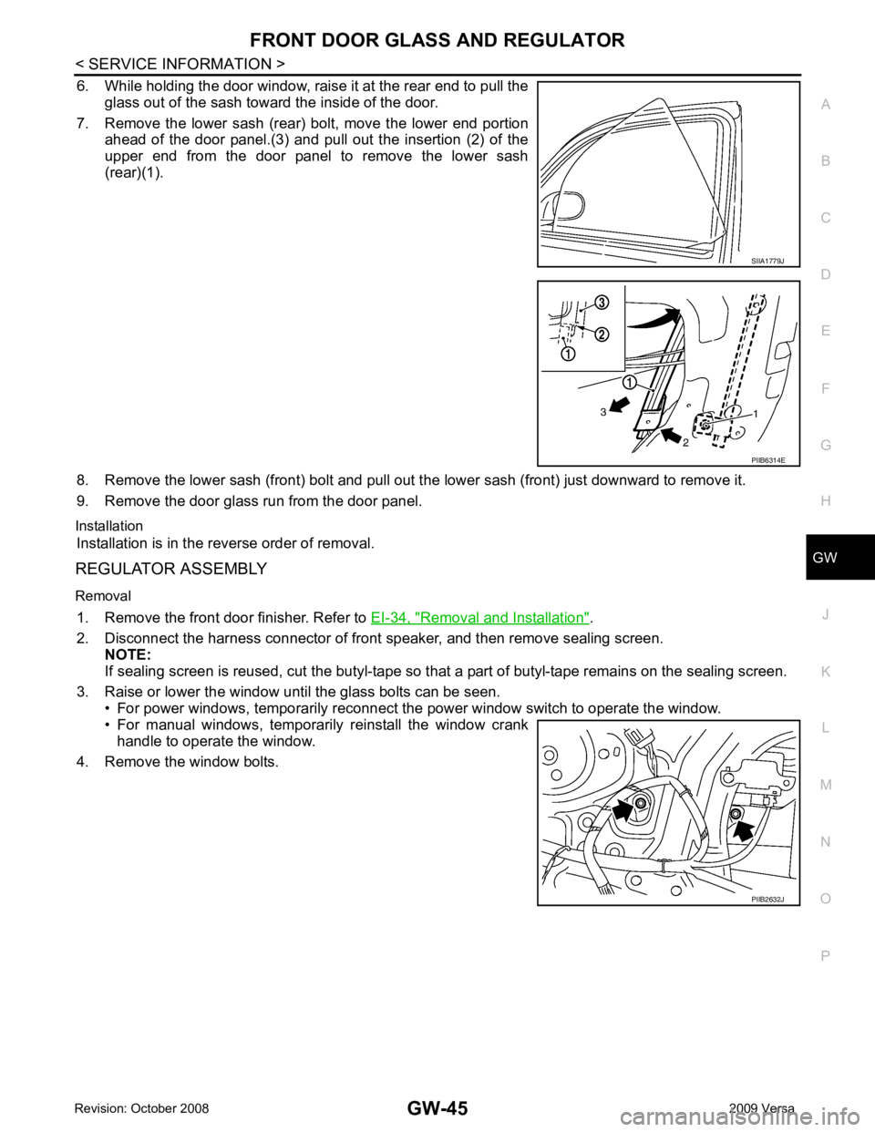
6. While holding the door window, raise it at the rear end to pull the
glass out of the sash toward the inside of the door.
7. Remove the lower sash (rear) bolt, move the lower end portion ahead of the door panel.(3) and pull out the insertion (2) of the
upper end from the door panel to remove the lower sash
(rear)(1).
8. Remove the lower sash (front) bolt and pull out the lower sash (front) just downward to remove it.
9. Remove the door glass run from the door panel.
Installation Installation is in the reverse order of removal.
REGULATOR ASSEMBLY
Removal 1. Remove the front door finisher. Refer to EI-34, " Removal and Installation " .
2. Disconnect the harness connector of front speaker, and then remove sealing screen. NOTE:
If sealing screen is reused, cut the butyl-tape so that a part of butyl-tape remains on the sealing screen.
3. Raise or lower the window until the glass bolts can be seen. • For power windows, temporarily reconnect t he power window switch to operate the window.
• For manual windows, temporarily reinstall the window crank handle to operate the window.
4. Remove the window bolts. PIIB6314E
PIIB2632J
Page 3352 of 4331
GW
N
O P
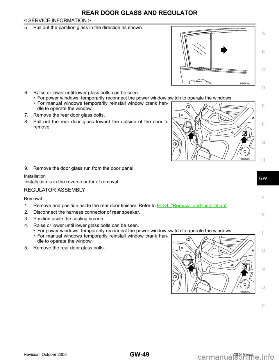
5. Pull out the partition glass in the direction as shown.
6. Raise or lower until lower glass bolts can be seen. • For power windows, temporarily reconnect the power window switch to operate the windows.
• For manual windows temporarily reinstall window crank han-
dle to operate the window.
7. Remove the rear door glass bolts.
8. Pull out the rear door glass toward the outside of the door to remove.
9. Remove the door glass run from the door panel.
Installation Installation is in the reverse order of removal.
REGULATOR ASSEMBLY
Removal 1. Remove and position aside the rear door finisher. Refer to EI-34, " Removal and Installation " .
2. Disconnect the harness connector of rear speaker.
3. Position aside the sealing screen.
4. Raise or lower until lower glass bolts can be seen. • For power windows, temporarily reconnect the power window switch to operate the windows.
• For manual windows temporarily reinstall window crank han- dle to operate the window.
5. Remove the rear door glass bolts. PIIB2637J
PIIB2637J
Page 3627 of 4331
LT
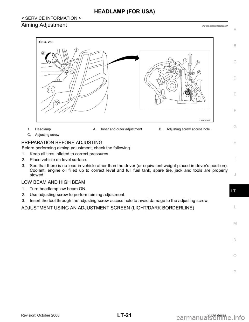
N
O P
Aiming Adjustment
INFOID:0000000004306537
PREPARATION BEFORE ADJUSTING Before performing aiming adjustment, check the following.
1. Keep all tires inflated to correct pressures.
2. Place vehicle on level surface.
3. See that there is no-load in vehicle other than the driv er (or equivalent weight placed in driver's position).
Coolant, engine oil filled up to correct level and full fuel tank, spare tire, jack and tools are properly
stowed.
LOW BEAM AND HIGH BEAM 1. Turn headlamp low beam ON.
2. Use adjusting screw to perform aiming adjustment.
3. Insert the tool through the adjusting screw acce ss hole to avoid damage to the adjusting screw.
ADJUSTMENT USING AN ADJUSTMENT SCREEN (LIGHT/DARK BORDERLINE) 1. Headlamp A. Inner and outer adjustment B. Adjusting screw access hole
C. Adjusting screw
Page 3629 of 4331
LT
N
O P
2. Remove the headlamp. Refer to
LT-23, " Removal and Installation " .
3. Turn bulb socket counterclockwise and unlock it.
4. Remove bulb from its socket.
FRONT TURN SIGNAL LAMP 1. Turn lighting switch OFF.
2. Remove the headlamp. Refer to LT-23, " Removal and Installation " .
3. Turn bulb socket counterclockwise and unlock it.
4. Remove bulb from its socket.
Removal and Installation INFOID:0000000004306539
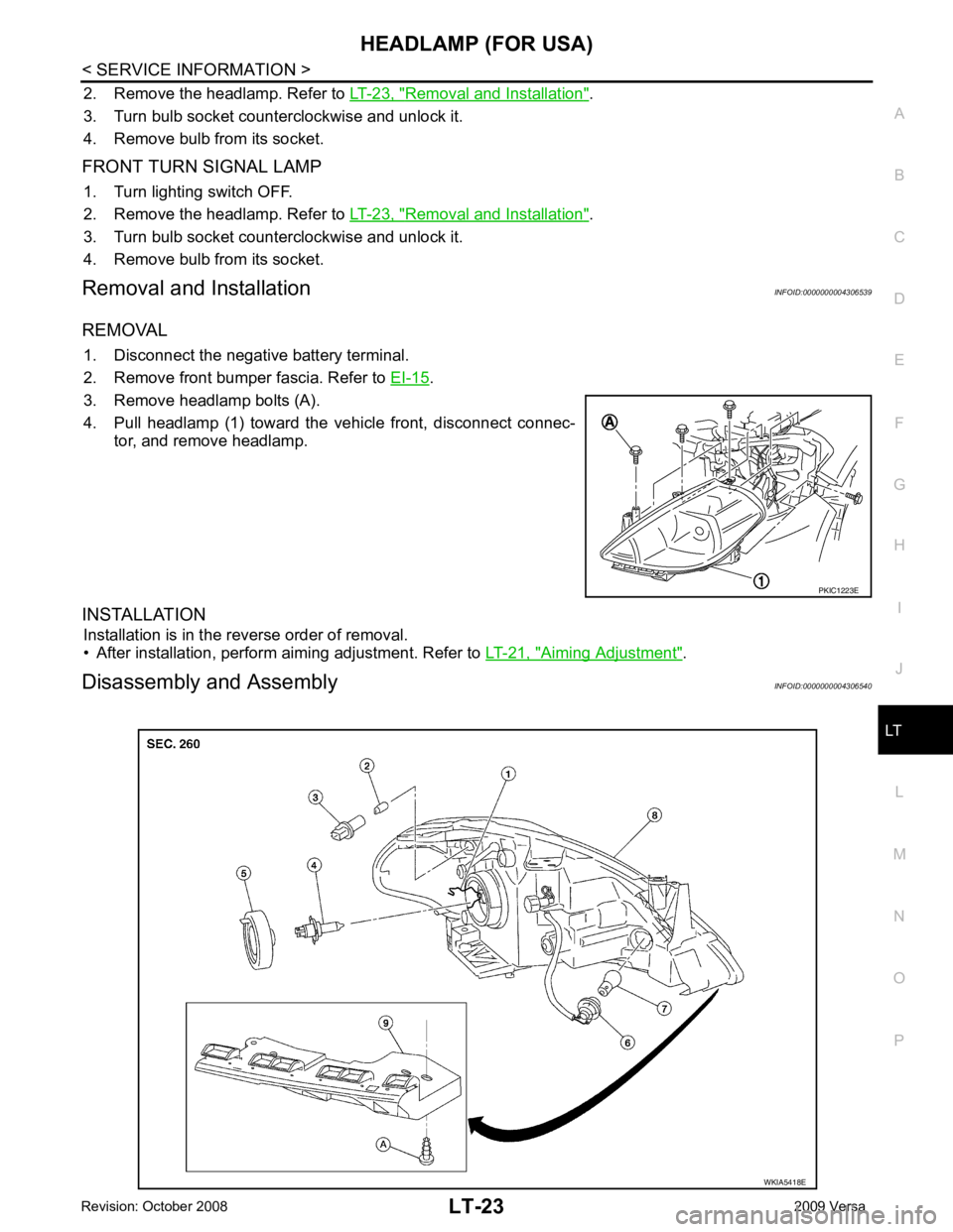
REMOVAL 1. Disconnect the negative battery terminal.
2. Remove front bumper fascia. Refer to EI-15 .
3. Remove headlamp bolts (A).
4. Pull headlamp (1) toward the vehicle front, disconnect connec- tor, and remove headlamp.
INSTALLATION Installation is in the reverse order of removal.
• After installation, perform aiming adjustment. Refer to LT-21, " Aiming Adjustment " .
Disassembly and Assembly INFOID:0000000004306540 WKIA5418E
Page 3641 of 4331
HEADLAMP (FOR CANADA) - DA
YTIME LIGHT SYSTEM -
LT-35
< SERVICE INFORMATION >
C
D E
F
G H
I
J
L
M A
B LT
N
O P
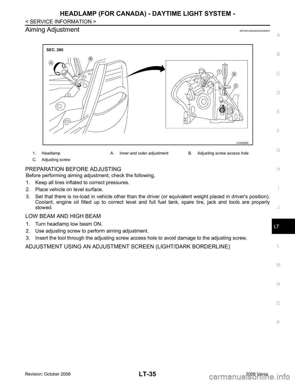
Aiming Adjustment
INFOID:0000000004306553
PREPARATION BEFORE ADJUSTING Before performing aiming adjustment, check the following.
1. Keep all tires inflated to correct pressures.
2. Place vehicle on level surface.
3. Set that there is no-load in vehicle other than the driv er (or equivalent weight placed in driver's position).
Coolant, engine oil filled up to correct level and full fuel tank, spare tire, jack and tools are properly
stowed.
LOW BEAM AND HIGH BEAM 1. Turn headlamp low beam ON.
2. Use adjusting screw to perform aiming adjustment.
3. Insert the tool through the adjusting screw a ccess hole to avoid damage to the adjusting screw.
ADJUSTMENT USING AN ADJUSTMENT SCREEN (LIGHT/DARK BORDERLINE) 1. Headlamp A. Inner and outer adjustment B. Adjusting screw access hole
C. Adjusting screw LKIA0930E