NISSAN LATIO 2009 Service Repair Manual
LATIO 2009
NISSAN
NISSAN
https://www.carmanualsonline.info/img/5/57359/w960_57359-0.png
NISSAN LATIO 2009 Service Repair Manual
Trending: gas type, inflation pressure, child restraint, dashboard, fuel, tow, stop start
Page 3461 of 4331
YES >> GO TO 2.
NO >> Repair the terminal and connector. YES >> GO TO 3.
NO >> Repair the BCM branch line. BCM Power Supply and Ground
Circuit Inspection " .
Is the inspection result normal? YES (Present error)>>Replace the BCM. Refer to
BCS-18, " Removal and Installation of BCM " .
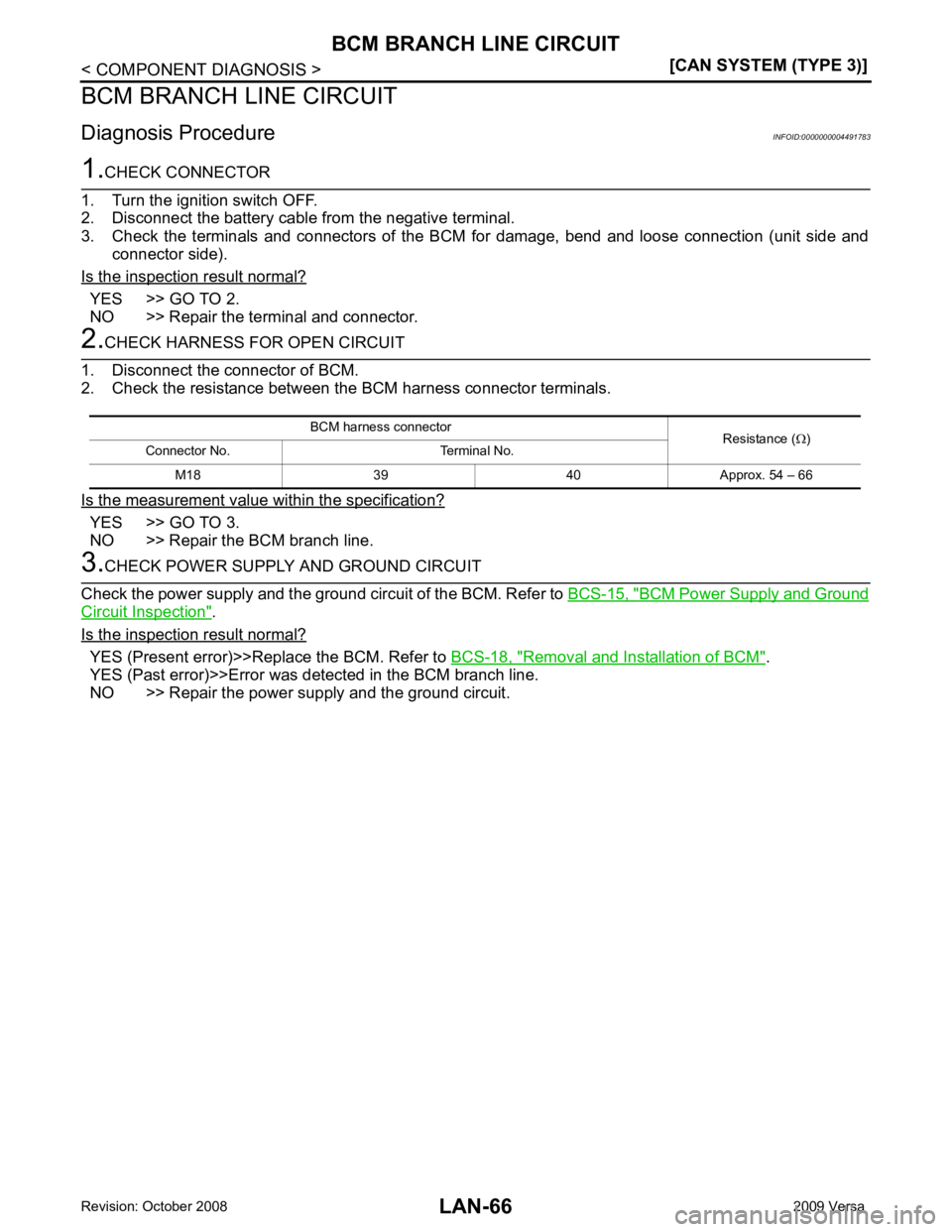
YES (Past error)>>Error was detected in the BCM branch line.
NO >> Repair the power supply and the ground circuit. BCM harness connector
Resistance (Ω)
Connector No. Terminal No.
M18 39 40 Approx. 54 – 66
Page 3462 of 4331
LAN
N
O P
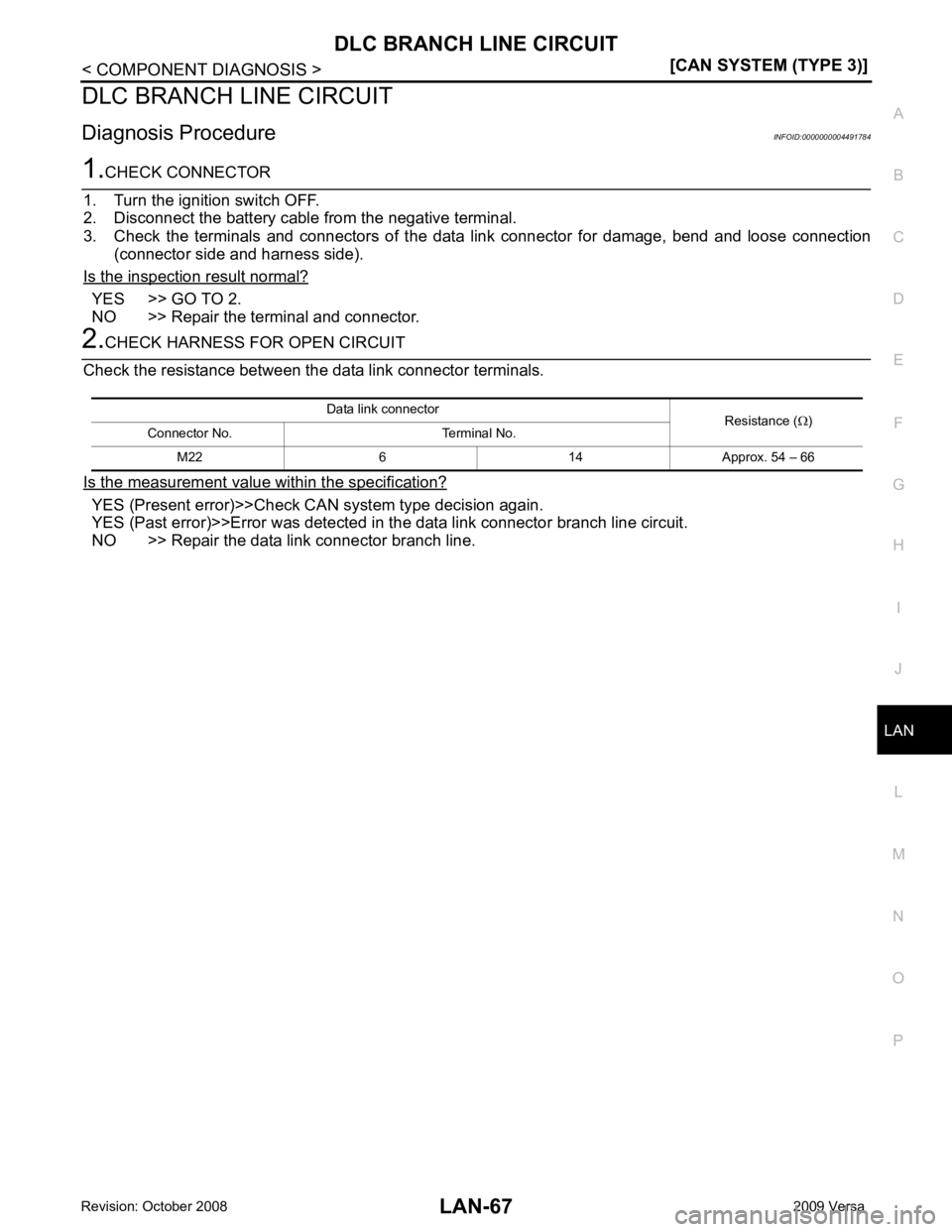
DLC BRANCH LINE CIRCUIT
Diagnosis Procedure INFOID:0000000004491784YES >> GO TO 2.
NO >> Repair the terminal and connector. YES (Present error)>>Check CA
N system type decision again.
YES (Past error)>>Error was detected in the data link connector branch line circuit.
NO >> Repair the data link connector branch line. Data link connector
Resistance (Ω)
Connector No. Terminal No.
M22 6 14 Approx. 54 – 66
Page 3463 of 4331
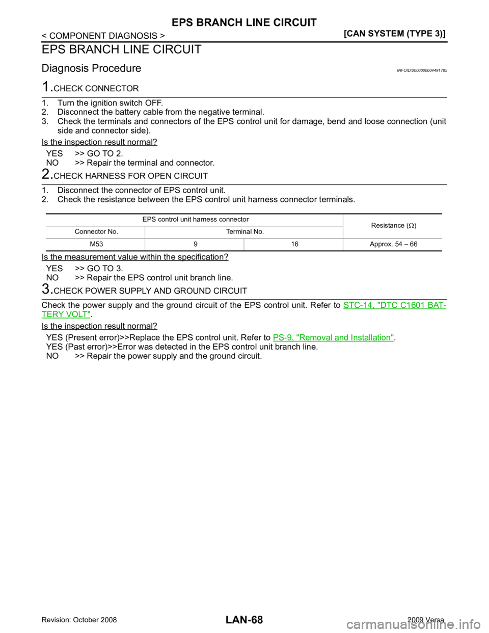
YES >> GO TO 2.
NO >> Repair the terminal and connector. YES >> GO TO 3.
NO >> Repair the EPS control unit branch line. DTC C1601 BAT-
TERY VOLT " .
Is the inspection result normal? YES (Present error)>>Replace the EPS control unit. Refer to
PS-9, " Removal and Installation " .
YES (Past error)>>Error was detected in the EPS control unit branch line.
NO >> Repair the power supply and the ground circuit. EPS control unit harness connector
Resistance (Ω)
Connector No. Terminal No.
M53 9 16 Approx. 54 – 66
Page 3464 of 4331
LAN
N
O P
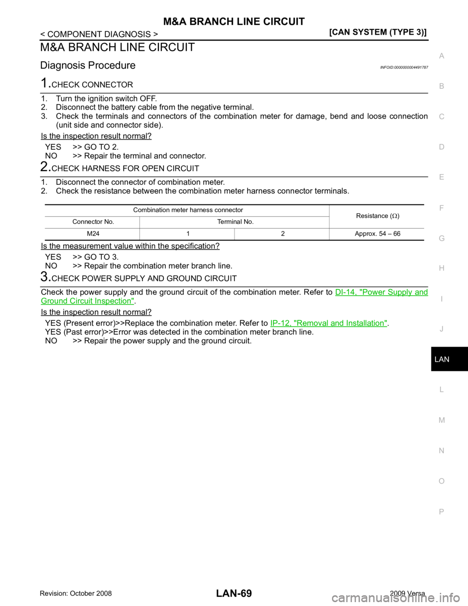
M&A BRANCH LINE CIRCUIT
Diagnosis Procedure INFOID:0000000004491787YES >> GO TO 2.
NO >> Repair the terminal and connector. YES >> GO TO 3.
NO >> Repair the combination meter branch line. Power Supply and
Ground Circuit Inspection " .
Is the inspection result normal? YES (Present error)>>Replace the combination meter. Refer to
IP-12, " Removal and Installation " .
YES (Past error)>>Error was detected in the combination meter branch line.
NO >> Repair the power supply and the ground circuit. Combination meter harness connector
Resistance (Ω)
Connector No. Terminal No.
M24 1 2 Approx. 54 – 66
Page 3465 of 4331
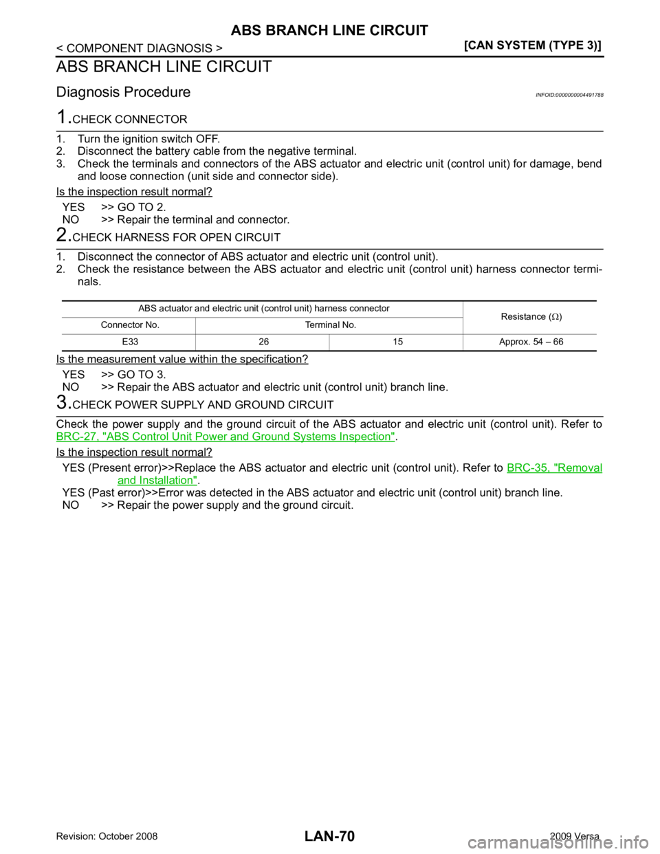
YES >> GO TO 2.
NO >> Repair the terminal and connector. YES >> GO TO 3.
NO >> Repair the ABS actuator and electric unit (control unit) branch line. ABS Control Unit Power and Ground Systems Inspection " .
Is the inspection result normal? YES (Present error)>>Replace t
he ABS actuator and electric unit (control unit). Refer to BRC-35, " Removal
and Installation " .
YES (Past error)>>Error was detected in the ABS ac tuator and electric unit (control unit) branch line.
NO >> Repair the power supply and the ground circuit. ABS actuator and electric unit (c
ontrol unit) harness connector
Resistance (Ω)
Connector No. Terminal No.
E33 26 15 Approx. 54 – 66
Page 3466 of 4331
LAN
N
O P
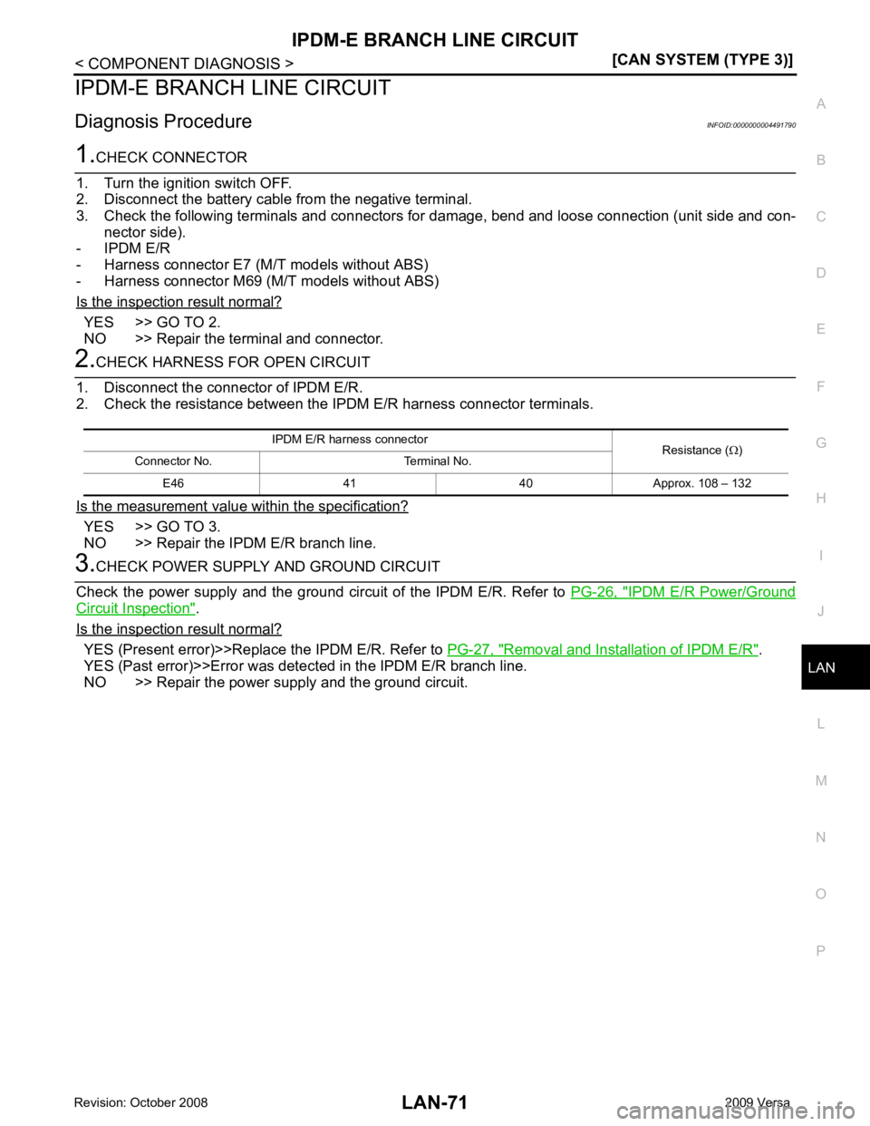
IPDM-E BRANCH
LINE CIRCUIT
Diagnosis Procedure INFOID:0000000004491790YES >> GO TO 2.
NO >> Repair the terminal and connector. YES >> GO TO 3.
NO >> Repair the IPDM E/R branch line. IPDM E/R Power/Ground
Circuit Inspection " .
Is the inspection result normal? YES (Present error)>>Replace the IPDM E/R. Refer to
PG-27, " Removal and Installation of IPDM E/R " .
YES (Past error)>>Error was detec ted in the IPDM E/R branch line.
NO >> Repair the power supply and the ground circuit. IPDM E/R harness connector
Resistance (Ω)
Connector No. Terminal No.
E46 41 40 Approx. 108 – 132
Page 3467 of 4331
![NISSAN LATIO 2009 Service Repair Manual LAN-72< COMPONENT DIAGNOSIS >
[CAN SYSTEM (TYPE 3)]
CAN COMMUNICATION CIRCUIT
CAN COMMUNICATION CIRCUIT
Diagnosis Procedure INFOID:00000000044917911.
CONNECTOR INSPECTION
1. Turn the ignition switch O NISSAN LATIO 2009 Service Repair Manual LAN-72< COMPONENT DIAGNOSIS >
[CAN SYSTEM (TYPE 3)]
CAN COMMUNICATION CIRCUIT
CAN COMMUNICATION CIRCUIT
Diagnosis Procedure INFOID:00000000044917911.
CONNECTOR INSPECTION
1. Turn the ignition switch O](/img/5/57359/w960_57359-3466.png)
LAN-72< COMPONENT DIAGNOSIS >
[CAN SYSTEM (TYPE 3)]
CAN COMMUNICATION CIRCUIT
CAN COMMUNICATION CIRCUIT
Diagnosis Procedure INFOID:00000000044917911.
CONNECTOR INSPECTION
1. Turn the ignition switch OFF.
2. Disconnect the battery cable from the negative terminal.
3. Disconnect all the unit connectors on CAN communication system.
4. Check terminals and connectors for damage, bend and loose connection.
Is the inspection result normal? YES >> GO TO 2.
NO >> Repair the terminal and connector. 2.
CHECK HARNESS CONTI NUITY (SHORT CIRCUIT)
Check the continuity between t he data link connector terminals.
Is the inspection result normal? YES >> GO TO 3.
NO >> Check the harness and repair the root cause. 3.
CHECK HARNESS CONTI NUITY (SHORT CIRCUIT)
Check the continuity between the data link connector and the ground.
Is the inspection result normal? YES >> GO TO 4.
NO >> Check the harness and repair the root cause. 4.
CHECK ECM AND IPDM E/R TERMINATION CIRCUIT
1. Remove the ECM and the IPDM E/R.
2. Check the resistance between the ECM terminals.
3. Check the resistance between the IPDM E/R terminals.
Is the measurement value within the specification? YES >> GO TO 5.
NO >> Replace the ECM and/or the IPDM E/R. 5.
CHECK SYMPTOM
Connect all the connectors. Check if the symptoms descri bed in the “Symptom (Results from interview with
customer)” are reproduced. Data link connector
Continuity
Connector No. Terminal No.
M22 6 14 Not existed Data link connector
GroundContinuity
Connector No. Terminal No.
M22 6 Not existed
14 Not existed ECM
Resistance (Ω)
Terminal No.
84 83 Approx. 108 – 132
IPDM E/R Resistance (Ω)
Terminal No.
41 40 Approx. 108 – 132 LKIA0037E
Page 3468 of 4331
LAN
N
O P
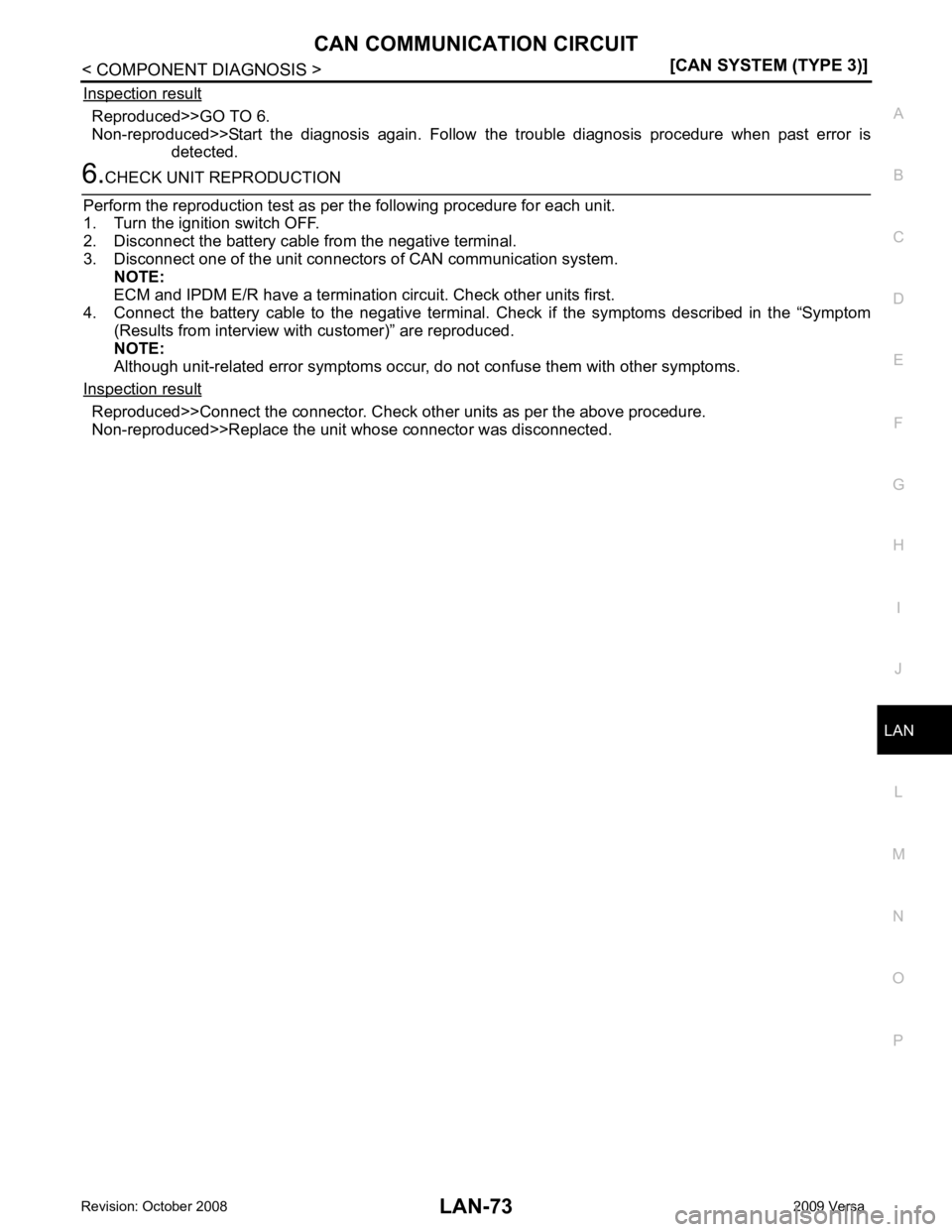
Inspection result Reproduced>>GO TO 6.
Non-reproduced>>Start the diagnosis again. Follow the trouble diagnosis procedure when past error is
detected. Reproduced>>Connect the connector. Check other units as per the above procedure.
Non-reproduced>>Replace the unit whose connector was disconnected.
Page 3469 of 4331
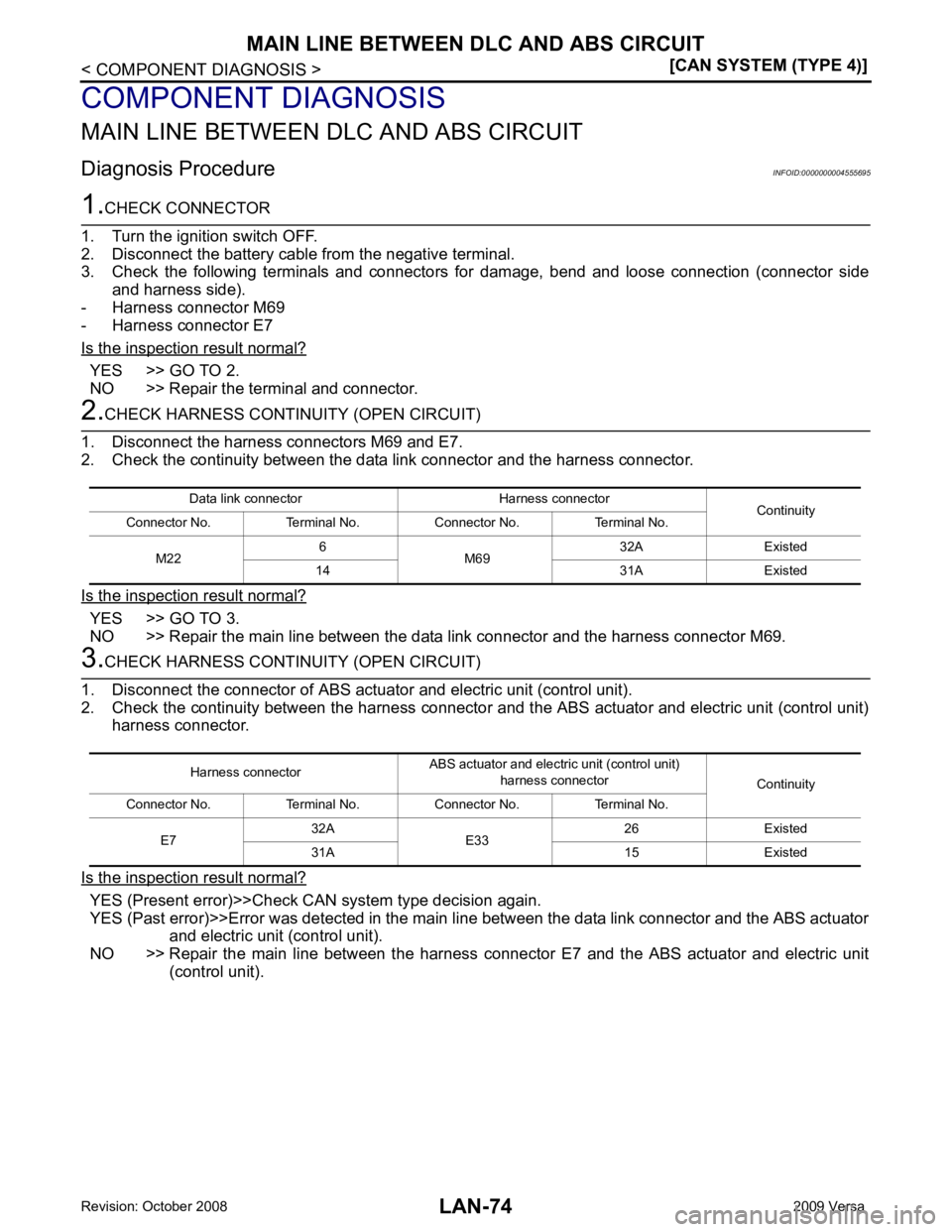
YES >> GO TO 2.
NO >> Repair the terminal and connector. YES >> GO TO 3.
NO >> Repair the main line between the data link connector and the harness connector M69.YES (Present error)>>Check CAN system type decision again.
YES (Past error)>>Error was detected in the main line between the data link connector and the ABS actuator
and electric unit (control unit).
NO >> Repair the main line between the harness connec tor E7 and the ABS actuator and electric unit
(control unit). Data link connector Harness connector
Continuity
Connector No. Terminal No. Connector No. Terminal No.
M22 6
M69 32A Existed
14 31A Existed Harness connector
ABS actuator and electric unit (control unit)
harness connector Continuity
Connector No. Terminal No. Connector No. Terminal No.
E7 32A
E33 26 Existed
31A 15 Existed
Page 3470 of 4331
LAN
N
O P
ECM BRANCH LINE CIRCUIT
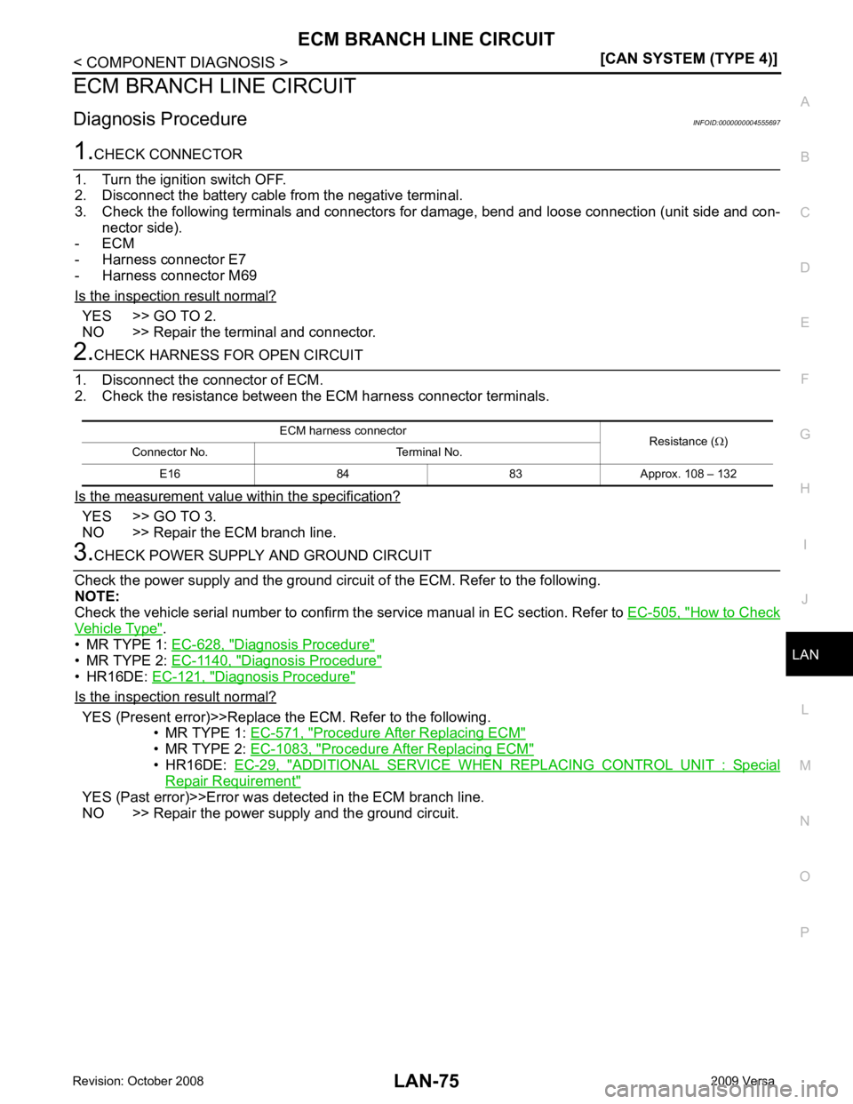
Diagnosis Procedure INFOID:0000000004555697YES >> GO TO 2.
NO >> Repair the terminal and connector. YES >> GO TO 3.
NO >> Repair the ECM branch line. How to Check
Vehicle Type " .
• MR TYPE 1: EC-628, " Diagnosis Procedure "
• MR TYPE 2:
EC-1140, " Diagnosis Procedure "
• HR16DE:
EC-121, " Diagnosis Procedure "
Is the inspection result normal?
YES (Present error)>>Replace the ECM. Refer to the following.
• MR TYPE 1: EC-571, " Procedure After Replacing ECM "
• MR TYPE 2:
EC-1083, " Procedure After Replacing ECM "
• HR16DE:
EC-29, " ADDITIONAL SERVICE WHEN REPLACING CONTROL UNIT : Special
Repair Requirement "
YES (Past error)>>Error was det
ected in the ECM branch line.
NO >> Repair the power supply and the ground circuit. ECM harness connector
Resistance (Ω)
Connector No. Terminal No.
E16 84 83 Approx. 108 – 132
Trending: power steering fluid, engine overheat, fuel filter, hood open, jump cable, key fob battery, phone
![NISSAN LATIO 2009 Service Repair Manual LAN-72< COMPONENT DIAGNOSIS >
[CAN SYSTEM (TYPE 3)]
CAN COMMUNICATION CIRCUIT
CAN COMMUNICATION CIRCUIT
Diagnosis Procedure INFOID:00000000044917911.
CONNECTOR INSPECTION
1. Turn the ignition switch O NISSAN LATIO 2009 Service Repair Manual LAN-72< COMPONENT DIAGNOSIS >
[CAN SYSTEM (TYPE 3)]
CAN COMMUNICATION CIRCUIT
CAN COMMUNICATION CIRCUIT
Diagnosis Procedure INFOID:00000000044917911.
CONNECTOR INSPECTION
1. Turn the ignition switch O](/img/5/57359/w960_57359-3466.png)
