battery NISSAN LATIO 2009 Service Owner's Guide
[x] Cancel search | Manufacturer: NISSAN, Model Year: 2009, Model line: LATIO, Model: NISSAN LATIO 2009Pages: 4331, PDF Size: 58.04 MB
Page 206 of 4331
TROUBLE DIAGNOSIS FOR SYMPTOMS
AT-201
< SERVICE INFORMATION >
D
E
F
G H
I
J
K L
M A
B AT
N
O P
OK >> GO TO 3
NG >> Check PNP switch. Refer to AT-176, " Component Inspection " .
2.
CHECK PNP SWITCH CIRCUIT
Without CONSULT-III
1. Turn ignition switch ON. (Do not start engine.)
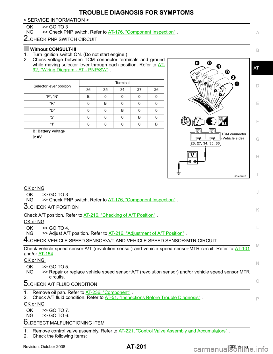
2. Check voltage between TCM connector terminals and ground
while moving selector lever through each position. Refer to AT-92, " Wiring Diagram - AT - PNP/SW " .
B: Battery voltage
0: 0V
OK or NG OK >> GO TO 3
NG >> Check PNP switch. Refer to AT-176, " Component Inspection " .
3.
CHECK A/T POSITION
Check A/T position. Refer to AT-216, " Checking of A/T Position " .
OK or NG OK >> GO TO 4.
NG >> Adjust A/T position. Refer to AT-216, " Adjustment of A/T Position " .
4.
CHECK VEHICLE SPEED SENS OR·A/T AND VEHICLE SPEED SENSOR·MTR CIRCUIT
Check vehicle speed sensor·A/T (re volution sensor) and vehicle speed sensor·MTR circuit. Refer to AT-101and/or
AT-154 .
OK or NG OK >> GO TO 5.
NG >> Repair or replace vehicle speed sensor·A/T (revolution sensor) and/or vehicle speed sensor·MTR
circuits. 5.
CHECK A/T FLUID CONDITION
1. Remove oil pan. Refer to AT-236, " Component " .
2. Check A/T fluid condition. Refer to AT-51, " Inspections Before Trouble Diagnosis " .
OK or NG OK >> GO TO 7.
NG >> GO TO 6. 6.
DETECT MALFUNCTIONING ITEM
1. Remove control valve assembly. Refer to AT-221, " Control Valve Assembly and Accumulators " .
2. Check the following items: Selector lever position
Terminal
36 35 34 27 26
“P”, “N” B 0 0 0 0 “R” 0 B 0 0 0
“D” 0 0 B 0 0 “2” 0 0 0 B 0
“1” 0 0 0 0 B SCIA7162E
Page 208 of 4331
TROUBLE DIAGNOSIS FOR SYMPTOMS
AT-203
< SERVICE INFORMATION >
D
E
F
G H
I
J
K L
M A
B AT
N
O P
Without CONSULT-III
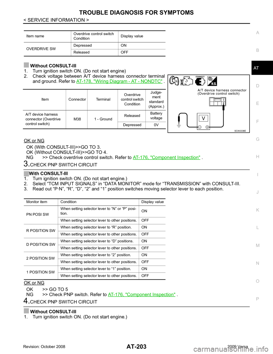
1. Turn ignition switch ON. (Do not start engine)
2. Check voltage between A/T device harness connector terminal and ground. Refer to AT-178, " Wiring Diagram - AT - NONDTC " .
OK or NG OK (With CONSULT-III)>>GO TO 3.
OK (Without CONSULT-III)>>GO TO 4.
NG >> Check overdrive control switch. Refer to AT-176, " Component Inspection " .
3.
CHECK PNP SWITCH CIRCUIT
With CONSULT-III
1. Turn ignition switch ON. (Do not start engine.)
2. Select “TCM INPUT SIGNALS” in “DATA MONI TOR” mode for “TRANSMISSION” with CONSULT-III.
3. Read out “P·N”, “R”, “D”, “2” and “1” position switches moving selector lever to each position.
OK or NG OK >> GO TO 5
NG >> Check PNP switch. Refer to AT-176, " Component Inspection " .
4.
CHECK PNP SWITCH CIRCUIT
Without CONSULT-III
1. Turn ignition switch ON. (Do not start engine.) Item name
Overdrive control switch
Condition Display value
OVERDRIVE SW Depressed ON
Released OFF Item Connector Terminal
Overdrive
control switch Condition Judge-
ment
standard
(Approx.)
A/T device harness
connector (Overdrive
control switch) M38 1 - Ground
Released
Battery
voltage
Depressed 0V SCIA5336E
Monitor item Condition Display value
PN POSI SW When setting selector le
ver to “N” or “P” posi-
tion. ON
When setting selector lever to other positions. OFF
R POSITION SW When setting selector lever to “R” position. ON
When setting selector lever to other positions. OFF
D POSITION SW When setting selector lever to “D” positions. ON
When setting selector lever to other positions. OFF
2 POSITION SW When setting selector lever to “2” position. ON
When setting selector lever to other positions. OFF
1 POSITION SW When setting selector lever to “1” position. ON
When setting selector lever to other positions. OFF
Page 209 of 4331
AT-204< SERVICE INFORMATION >
TROUBLE DIAGNOSIS FOR SYMPTOMS
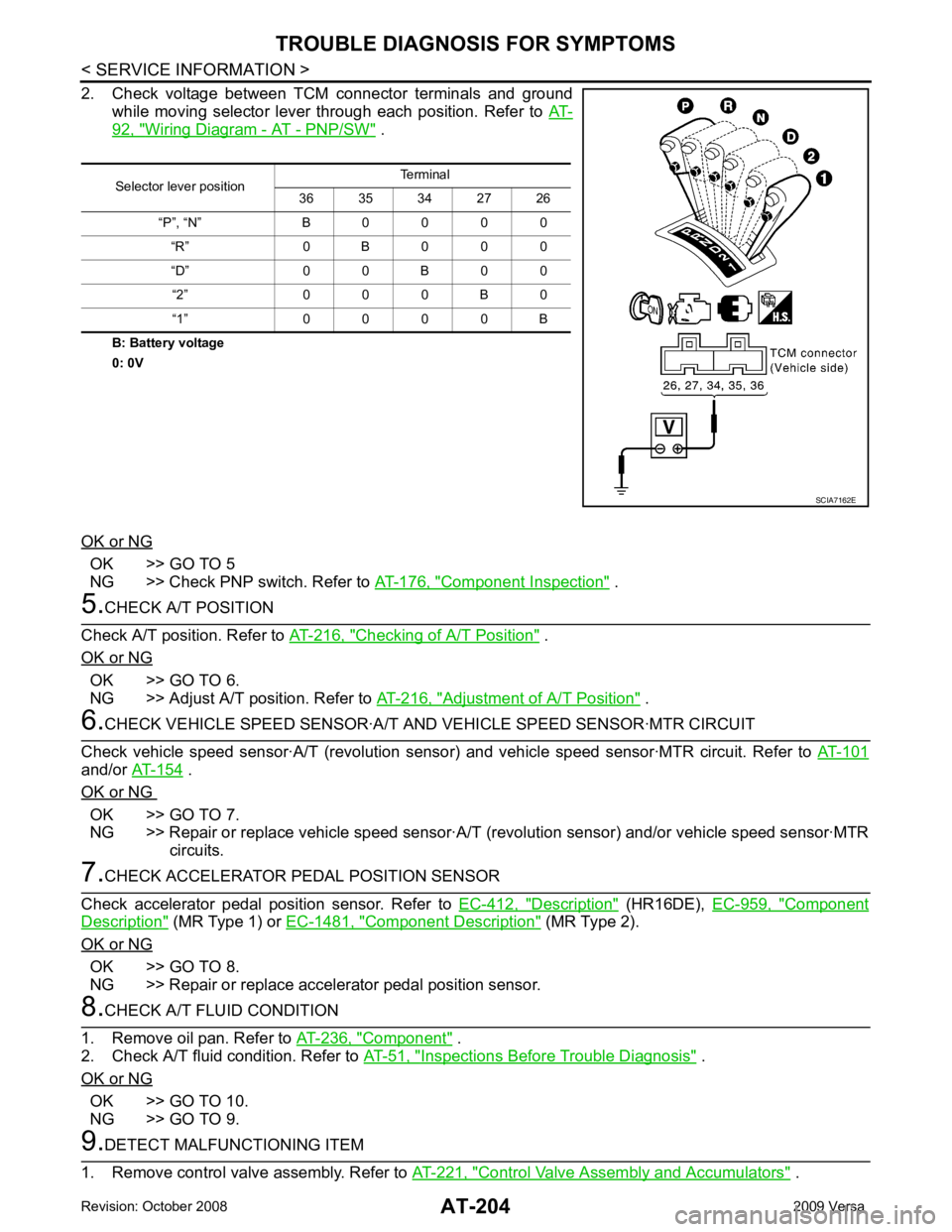
2. Check voltage between TCM connector terminals and ground while moving selector lever through each position. Refer to AT-92, " Wiring Diagram - AT - PNP/SW " .
B: Battery voltage
0: 0V
OK or NG OK >> GO TO 5
NG >> Check PNP switch. Refer to AT-176, " Component Inspection " .
5.
CHECK A/T POSITION
Check A/T position. Refer to AT-216, " Checking of A/T Position " .
OK or NG OK >> GO TO 6.
NG >> Adjust A/T position. Refer to AT-216, " Adjustment of A/T Position " .
6.
CHECK VEHICLE SPEED SENSOR·A/T A ND VEHICLE SPEED SENSOR·MTR CIRCUIT
Check vehicle speed sensor·A/T (revolution senso r) and vehicle speed sensor·MTR circuit. Refer to AT-101and/or
AT-154 .
OK or NG OK >> GO TO 7.
NG >> Repair or replace vehicle speed sensor·A/T (revolution sensor) and/or vehicle speed sensor·MTR
circuits. 7.
CHECK ACCELERATOR PEDAL POSITION SENSOR
Check accelerator pedal position sensor. Refer to EC-412, " Description " (HR16DE),
EC-959, " Component
Description " (MR Type 1) or
EC-1481, " Component Description " (MR Type 2).
OK or NG OK >> GO TO 8.
NG >> Repair or replace accelerator pedal position sensor. 8.
CHECK A/T FLUID CONDITION
1. Remove oil pan. Refer to AT-236, " Component " .
2. Check A/T fluid condition. Refer to AT-51, " Inspections Before Trouble Diagnosis " .
OK or NG OK >> GO TO 10.
NG >> GO TO 9. 9.
DETECT MALFUNCTIONING ITEM
1. Remove control valve assembly. Refer to AT-221, " Control Valve Assembly and Accumulators " .
Selector lever position
Terminal
36 35 34 27 26
“P”, “N” B 0 0 0 0 “R” 0 B 0 0 0
“D” 0 0 B 0 0 “2” 0 0 0 B 0
“1” 0 0 0 0 B SCIA7162E
Page 216 of 4331
AT
N
O P
TRANSMISSION CONTROL MODULE
Removal and Installation INFOID:0000000004305492
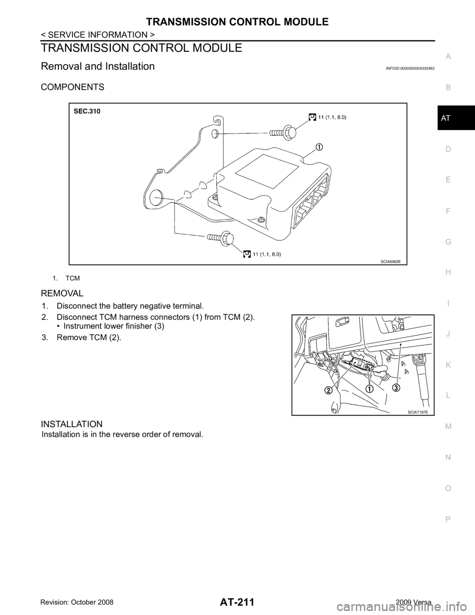
COMPONENTS
REMOVAL 1. Disconnect the battery negative terminal.
2. Disconnect TCM harness connectors (1) from TCM (2). • Instrument lower finisher (3)
3. Remove TCM (2).
INSTALLATION Installation is in the reverse order of removal. 1. TCM
Page 226 of 4331
AT
N
O P
ON-VEHICLE SERVICE
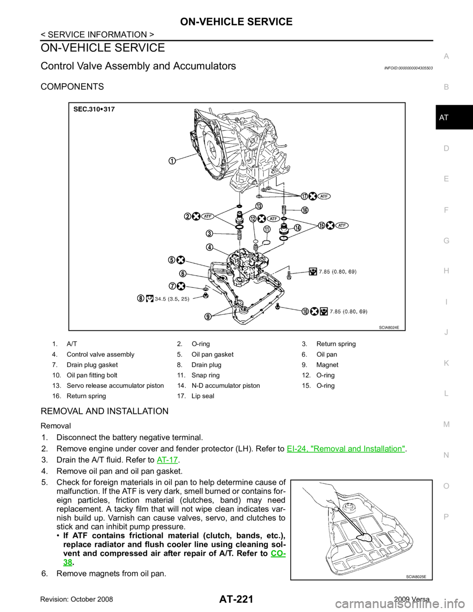
Control Valve Assembly and Accumulators INFOID:0000000004305503
COMPONENTS
REMOVAL AND INSTALLATION
Removal 1. Disconnect the battery negative terminal.
2. Remove engine under cover and fender protector (LH). Refer to EI-24, " Removal and Installation " .
3. Drain the A/T fluid. Refer to AT-17 .
4. Remove oil pan and oil pan gasket.
5. Check for foreign materials in oil pan to help determine cause of malfunction. If the ATF is very dark, smell burned or contains for-
eign particles, friction material (clutches, band) may need
replacement. A tacky film that will not wipe clean indicates var-
nish build up. Varnish can cause valves, servo, and clutches to
stick and can inhibit pump pressure.
• If ATF contains frictional material (clutch, bands, etc.),
replace radiator and flush cooler line using cleaning sol-
vent and compressed air after repair of A/T. Refer to CO-38 .
6. Remove magnets from oil pan. 1. A/T 2. O-ring 3. Return spring
4. Control valve assembly 5. Oil pan gasket 6. Oil pan
7. Drain plug gasket 8. Drain plug 9. Magnet
10. Oil pan fitting bolt 11. Snap ring 12. O-ring
13. Servo release accumulator piston 14. N-D accumulator piston 15. O-ring
16. Return spring 17. Lip seal SCIA8025E
Page 230 of 4331
AT
N
O P
REMOVAL AND INSTALLATION
Removal 1. Disconnect the battery negative terminal.
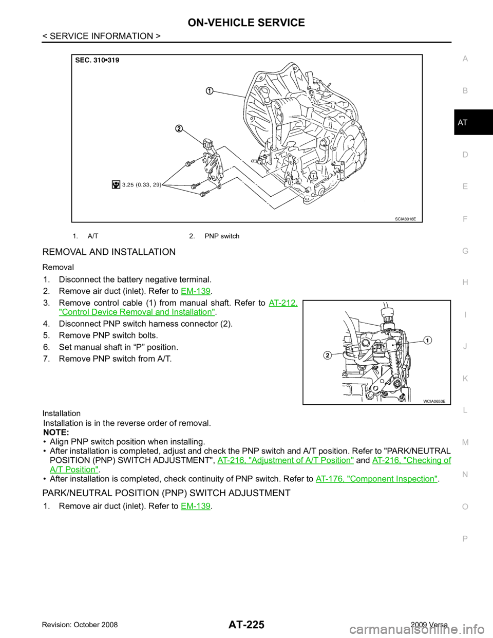
2. Remove air duct (inlet). Refer to EM-139 .
3. Remove control cable (1) from manual shaft. Refer to AT-212," Control Device Removal and Installation " .
4. Disconnect PNP switch harness connector (2).
5. Remove PNP switch bolts.
6. Set manual shaft in “P” position.
7. Remove PNP switch from A/T.
Installation Installation is in the reverse order of removal.
NOTE:
• Align PNP switch position when installing.
• After installation is completed, adjust and check the PNP switch and A/T position. Refer to "PARK/NEUTRAL
POSITION (PNP) SWITCH ADJUSTMENT", AT-216, " Adjustment of A/T Position " and
AT-216, " Checking of
A/T Position " .
• After installation is completed, check continuity of PNP switch. Refer to AT-176, " Component Inspection " .
PARK/NEUTRAL POSITION (PNP) SWITCH ADJUSTMENT 1. Remove air duct (inlet). Refer to EM-139 .
1. A/T 2. PNP switch
Page 231 of 4331
![NISSAN LATIO 2009 Service Owners Guide " Control Device Removal and Installation " .
4. Loosen PNP switch bolts. :Bolt
5. Insert the pin (3) [4 mm (0.16 in) dia.] straight into manual shaft (1) adjustment hole.
6. Rotate PNP switch (2)](/img/5/57359/w960_57359-230.png "NISSAN LATIO 2009 Service Owners Guide \" Control Device Removal and Installation \" .
4. Loosen PNP switch bolts. :Bolt
5. Insert the pin (3) [4 mm (0.16 in) dia.] straight into manual shaft (1) adjustment hole.
6. Rotate PNP switch (2)")
" Control Device Removal and Installation " .
4. Loosen PNP switch bolts. :Bolt
5. Insert the pin (3) [4 mm (0.16 in) dia.] straight into manual shaft (1) adjustment hole.
6. Rotate PNP switch (2) until the pin (3) can also be inserted straight into hole in PNP switch (2).
7. Tighten PNP switch bolts to the specified torque. Refer to "COMPONENTS".
8. Remove the pin (3) from adjustment hole after adjusting PNP switch (2).
9. Install the control cable. Refer to AT-212, " Control Device Removal and Installation " .
10. Adjust and check A/T position. Refer to AT-216, " Adjustment of A/T Position " and
AT-216, " Checking of A/
T Position " .
11. Check continuity of PNP switch (2). Refer to AT-176, " Component Inspection " .
12. Install the air duct (inlet). Refer to EM-139 .
Revolution Sensor INFOID:0000000004305505
COMPONENTS
REMOVAL AND INSTALLATION
Removal
1. Disconnect the battery negative terminal.
2. Remove air duct (inlet), air duct and air cleaner case. Refer to EM-139, " Component " .
Page 405 of 4331
AUDIO
AV-21
< SERVICE INFORMATION >
C
D E
F
G H
I
J
L
M A
B AV
N
O P
Terminal and Reference Valu
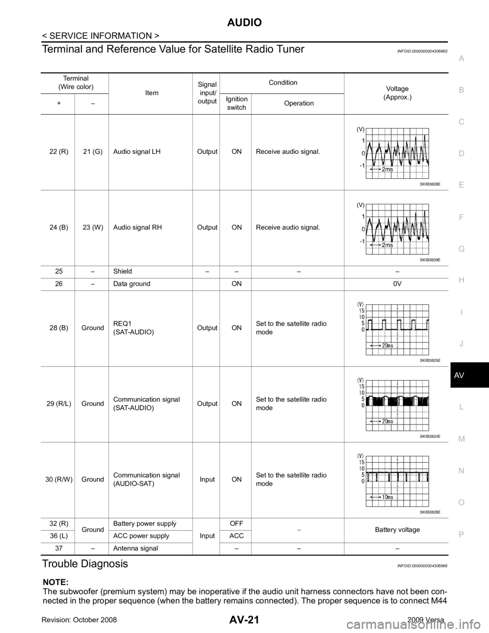
e for Satellite Radio Tuner INFOID:0000000004306965
Trouble Diagnosis INFOID:0000000004306966
NOTE:
The subwoofer (premium system) may be inoperative if the audio unit harness connectors have not been con-
nected in the proper sequence (when the battery remain s connected). The proper sequence is to connect M44
Terminal
(Wire color) ItemSignal
input/
output Condition
Voltage
(Approx.)
+ – Ignition
switch Operation
22 (R) 21 (G) Audio signal LH Output ON Receive audio signal.
24 (B) 23 (W) Audio signal RH Output ON Receive audio signal. 25 – Shield – – – –
26 – Data ground ON 0V
28 (B) Ground REQ1
(SAT-AUDIO) Output ONSet to the satellite radio
mode
29 (R/L) Ground Communication signal
(SAT-AUDIO) Output ONSet to the satellite radio
mode
30 (R/W) Ground Communication signal
(AUDIO-SAT) Input ON
Set to the satellite radio
mode
32 (R) GroundBattery power supply
InputOFF
− Battery voltage
36 (L) ACC power supply ACC
37 – Antenna signal – – – SKIB3609E
SKIB3609E
SKIB3825E
SKIB3824E
SKIB3826E
Page 407 of 4331
AV
N
O P
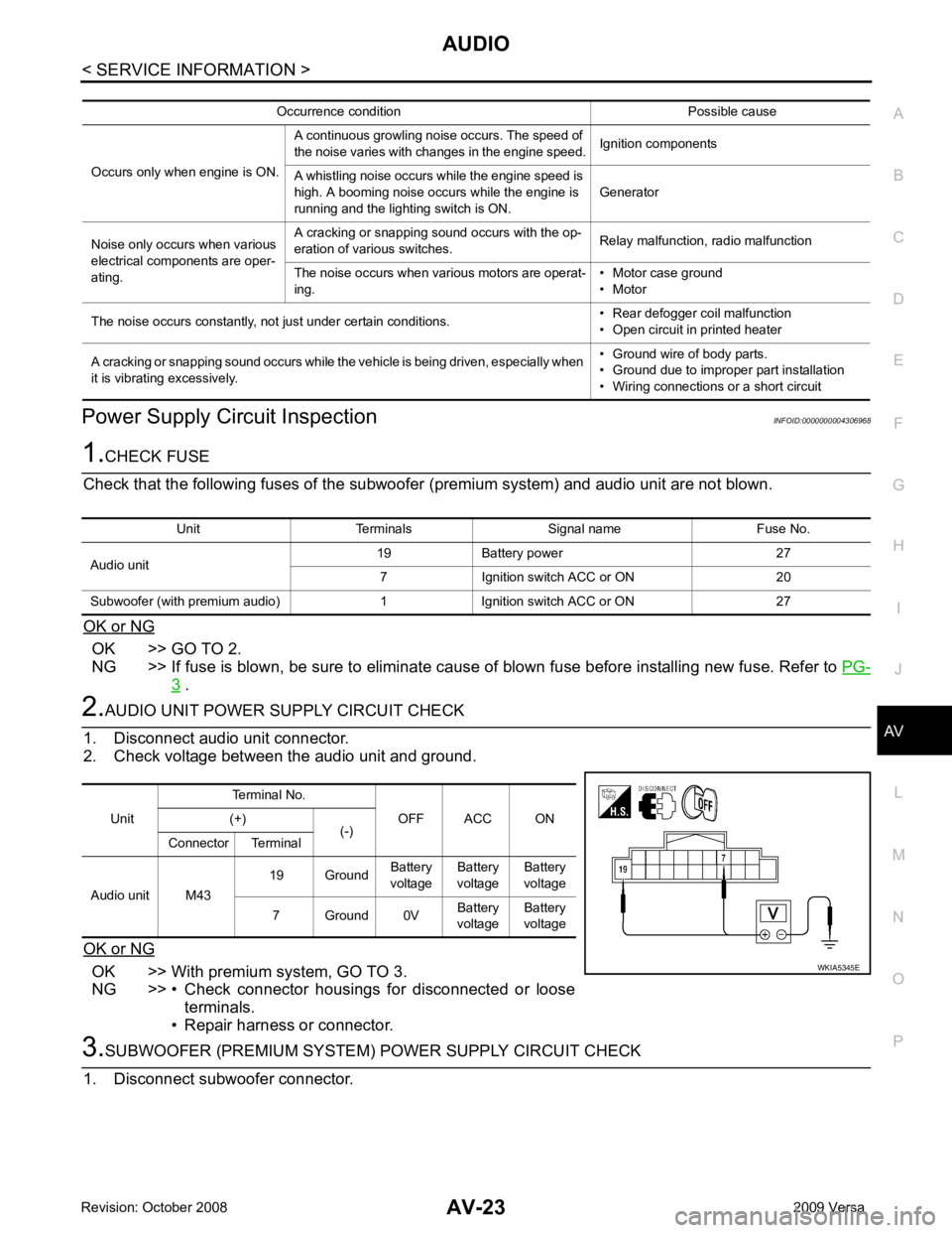
Power Supply Circuit Inspection
INFOID:0000000004306968OK >> GO TO 2.
NG >> If fuse is blown, be sure to eliminate cause of blown fuse before installing new fuse. Refer to PG-3 .
OK >> With premium system, GO TO 3.
NG >> • Check connector housings for disconnected or loose terminals.
• Repair harness or connector. Unit Terminals Signal name Fuse No.
Audio unit 19 Battery power 27
7 Ignition switch ACC or ON 20
Subwoofer (with premium audio) 1 Ignition switch ACC or ON 27 Unit
Terminal No.
OFF ACC ON
(+)
(-)
Connector Terminal
Audio unit M43 19 Ground
Battery
voltage Battery
voltage Battery
voltage
7 Ground 0V Battery
voltage Battery
voltage
Page 408 of 4331
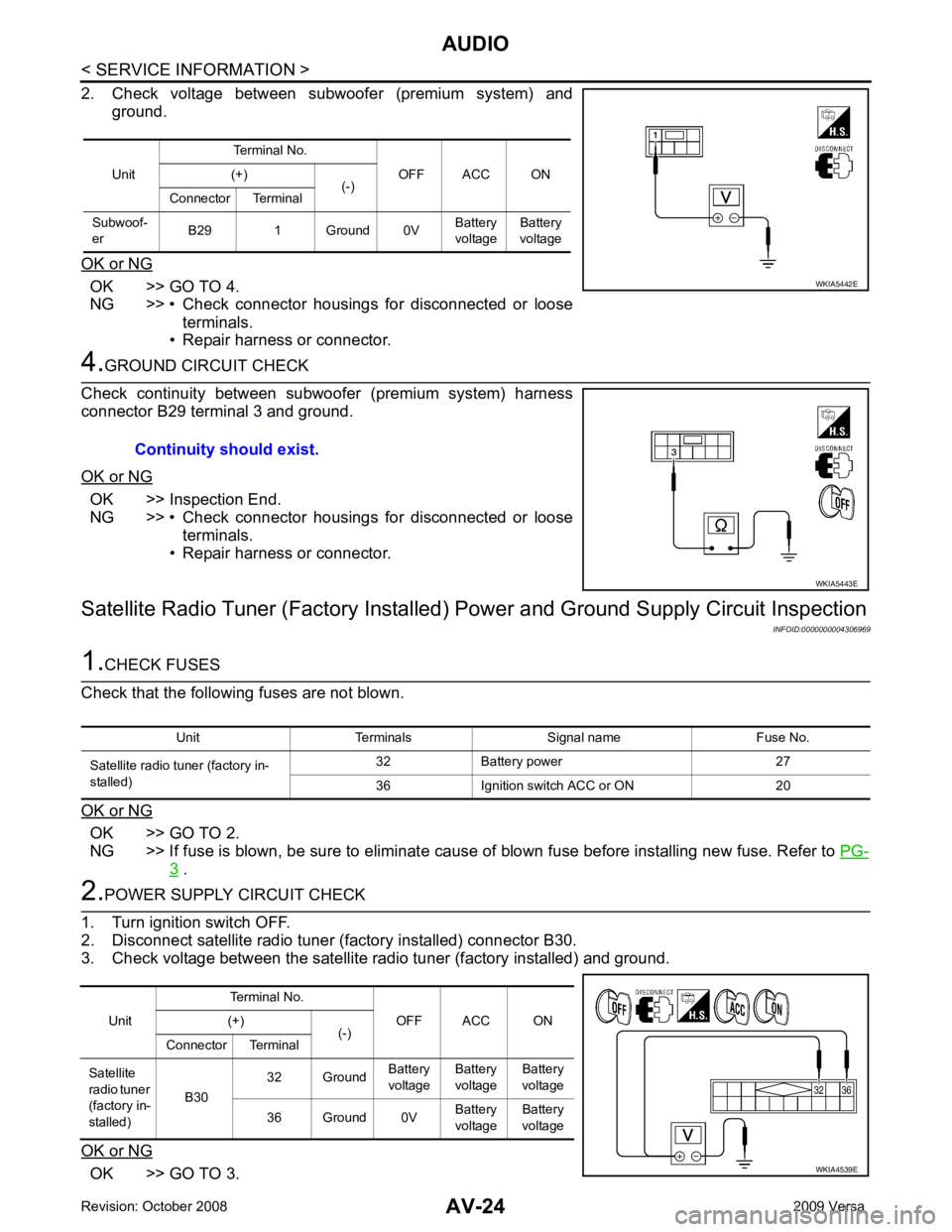
OK >> GO TO 4.
NG >> • Check connector housings for disconnected or loose
terminals.
• Repair harness or connector. OK >> Inspection End.
NG >> • Check connector housings for disconnected or loose
terminals.
• Repair harness or connector.
Satellite Radio Tuner (Factory Installed) Power and Ground Supply Circuit Inspection
INFOID:0000000004306969OK >> GO TO 2.
NG >> If fuse is blown, be sure to eliminate cause of blown fuse before installing new fuse. Refer to PG-3 .
OK >> GO TO 3.Unit
Terminal No.
OFF ACC ON
(+)
(-)
Connector Terminal
Subwoof-
er B29 1 Ground 0V Battery
voltage Battery
voltage Unit
Terminal No.
OFF ACC ON
(+)
(-)
Connector Terminal
Satellite
radio tuner
(factory in-
stalled) B30
32 Ground
Battery
voltage Battery
voltage Battery
voltage
36 Ground 0V Battery
voltage Battery
voltage