lock NISSAN LATIO 2009 Service Service Manual
[x] Cancel search | Manufacturer: NISSAN, Model Year: 2009, Model line: LATIO, Model: NISSAN LATIO 2009Pages: 4331, PDF Size: 58.04 MB
Page 220 of 4331
AT
N
O P
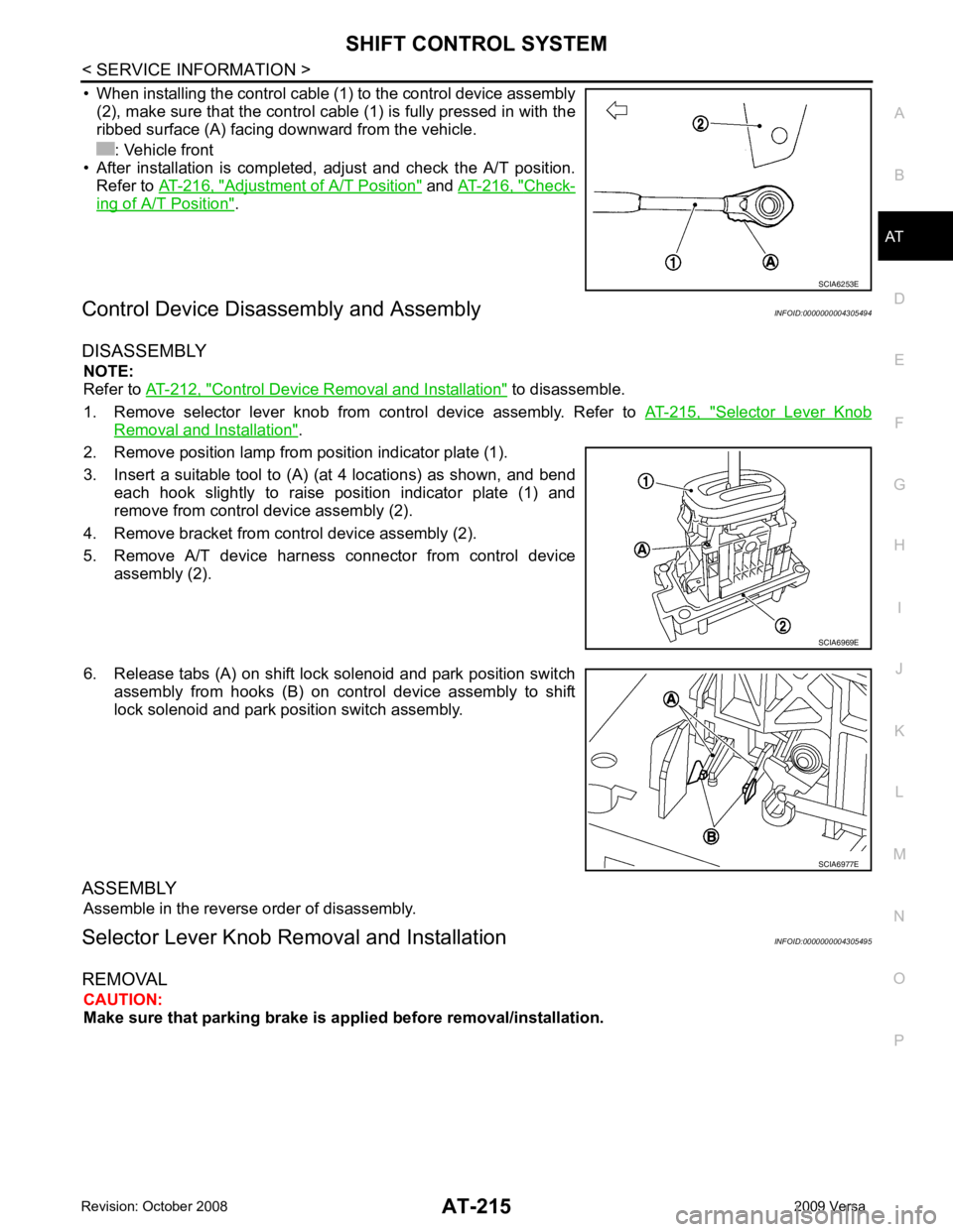
• When installing the control cable (1) to the control device assembly
(2), make sure that the control cable (1) is fully pressed in with the
ribbed surface (A) facing downward from the vehicle.
: Vehicle front
• After installation is completed, adjust and check the A/T position.
Refer to AT-216, " Adjustment of A/T Position " and
AT-216, " Check-
ing of A/T Position " .
Control Device Disassembly and Assembly INFOID:0000000004305494
DISASSEMBLY NOTE:
Refer to AT-212, " Control Device Removal and Installation " to disassemble.
1. Remove selector lever knob from control device assembly. Refer to AT-215, " Selector Lever Knob
Removal and Installation " .
2. Remove position lamp from position indicator plate (1).
3. Insert a suitable tool to (A) (at 4 locations) as shown, and bend each hook slightly to raise position indicator plate (1) and
remove from control device assembly (2).
4. Remove bracket from control device assembly (2).
5. Remove A/T device harness connector from control device assembly (2).
6. Release tabs (A) on shift lock solenoid and park position switch assembly from hooks (B) on control device assembly to shift
lock solenoid and park position switch assembly.
ASSEMBLY Assemble in the reverse order of disassembly.
Selector Lever Knob Re moval and Installation INFOID:0000000004305495
REMOVAL CAUTION:
Make sure that parking brake is a pplied before removal/installation.
Page 222 of 4331

AT
N
O P
5. The method of operating selector lever to individual positions
correctly should be as shown.
• (A): Press selector button to operate selector lever, while
depressing the brake pedal.
• (B): Press selector button to operate selector lever.
• (C): Selector lever can be operated without pressing selector
button.
6. Confirm back-up lamps illuminate only when selector lever is placed in “R” position. Confirm back-up lamps do not illuminate
when selector lever is in “P” or “N” position even if it is pushed
toward “R” position without pressing selector button.
7. Confirm engine can only be started with selector lever in “P” and “N” positions.
8. Make sure A/T is locked completely in “P” position.
Page 223 of 4331
Selector Lever Knob Removal and Installation " .
3. Remove the center console assembly. Refer to IP-11 .
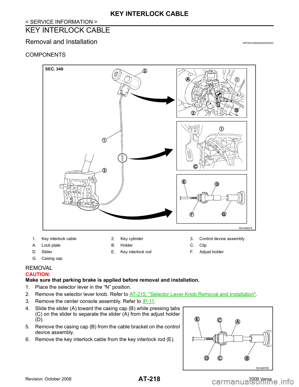
4. Slide the slider (A) toward the casing cap (B) while pressing tabs (C) on the slider to separate the slider (A) from the adjust holder
(D).
5. Remove the casing cap (B) from the cable bracket on the control
device assembly.
6. Remove the key interlock cable from the key interlock rod (E). 1. Key interlock cable 2. Key cylinder 3. Control device assembly
A. Lock plate B. Holder C. Clip
D. Slider E. Key interlock rod F. Adjust holder
G. Casing cap SCIA6975E
Page 224 of 4331
AT
N
O P
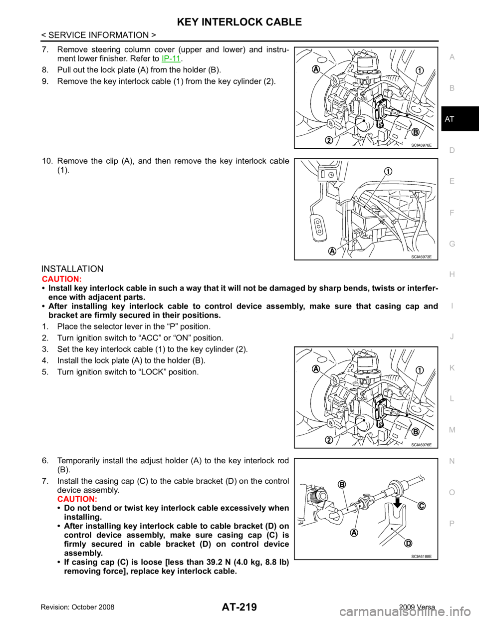
7. Remove steering column cover (upper and lower) and instru-
ment lower finisher. Refer to IP-11 .
8. Pull out the lock plate (A) from the holder (B).
9. Remove the key interlock cable (1) from the key cylinder (2).
10. Remove the clip (A), and then remove the key interlock cable (1).
INSTALLATION CAUTION:
• Install key interlock cable in such a way that it will not be damaged by sharp bends, twists or interfer-
ence with adjacent parts.
• After installing key interlock cable to contro l device assembly, make sure that casing cap and
bracket are firmly secured in their positions.
1. Place the selector lever in the “P” position.
2. Turn ignition switch to “ACC” or “ON” position.
3. Set the key interlock cable (1) to the key cylinder (2).
4. Install the lock plate (A) to the holder (B).
5. Turn ignition switch to “LOCK” position.
6. Temporarily install the adjust holder (A) to the key interlock rod (B).
7. Install the casing cap (C) to the cable bracket (D) on the control device assembly.
CAUTION:
• Do not bend or twist key interlock cable excessively when
installing.
• After installing key interlo ck cable to cable bracket (D) on
control device assembly, make sure casing cap (C) is
firmly secured in cable bracket (D) on control device
assembly.
• If casing cap (C) is loose [less than 39.2 N (4.0 kg, 8.8 lb)
removing force], replace key interlock cable.
Page 225 of 4331
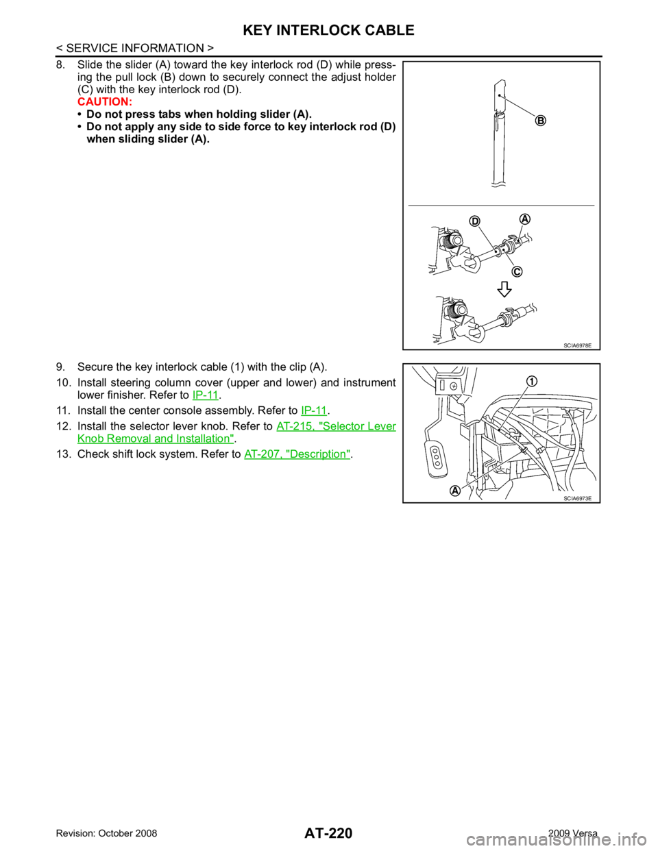
.
11. Install the center console assembly. Refer to IP-11 .
12. Install the selector lever knob. Refer to AT-215, " Selector Lever
Knob Removal and Installation " .
13. Check shift lock system. Refer to AT-207, " Description " .
SCIA6973E
Page 238 of 4331
AT
N
O P
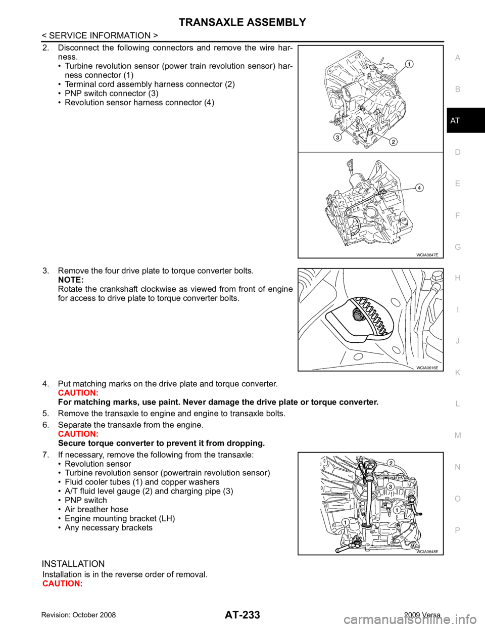
2. Disconnect the following connectors and remove the wire har-
ness.
• Turbine revolution sensor (power train revolution sensor) har-
ness connector (1)
• Terminal cord assembly harness connector (2)
• PNP switch connector (3)
• Revolution sensor harness connector (4)
3. Remove the four drive plate to torque converter bolts. NOTE:
Rotate the crankshaft clockwise as viewed from front of engine
for access to drive plate to torque converter bolts.
4. Put matching marks on the drive plate and torque converter. CAUTION:
For matching marks, use paint. Never dama ge the drive plate or torque converter.
5. Remove the transaxle to engine and engine to transaxle bolts.
6. Separate the transaxle from the engine. CAUTION:
Secure torque converter to prevent it from dropping.
7. If necessary, remove the following from the transaxle: • Revolution sensor
• Turbine revolution sensor (powertrain revolution sensor)
• Fluid cooler tubes (1) and copper washers
• A/T fluid level gauge (2) and charging pipe (3)
• PNP switch
• Air breather hose
• Engine mounting bracket (LH)
• Any necessary brackets
INSTALLATION Installation is in the reverse order of removal.
CAUTION: WCIA0616E
WCIA0648E
Page 242 of 4331

AT
N
O P
1. Pinion mate gear thrust washer 2. Pinion mate gear 3. Pinion mate shaft
4. Lock pin 5. Side gear 6. Side gear thrust washer
7. Differential side bearing 8. Speedometer drive gear 9. Differential case
10. Final gear 11. Differential side bearing adjusting shim 12. Plug
13. O-ring 14. Bracket 15. RH differential side oil seal
16. Torque converter 17. Converter housing 18. Differential lubricant tube
19. Clip 20. O-ring 21. O-ring
22. Oil pump housing oil seal 23. Oil pump housing 24. Outer gear
25. Inner gear 26. Oil pump cover 27. Seal ring
28. Oil pump assembly
Page 246 of 4331
AT
N
O P
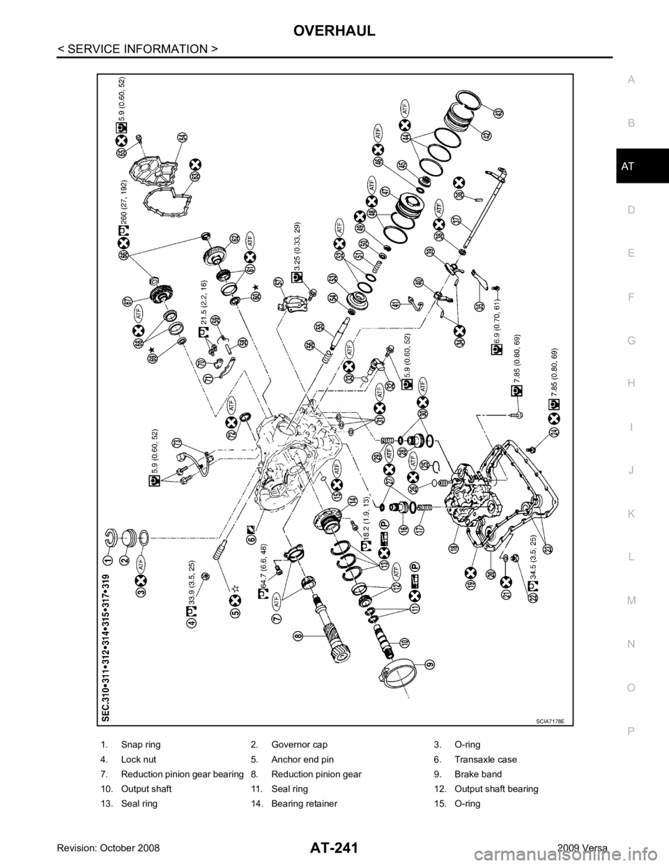
1. Snap ring 2. Governor cap 3. O-ring
4. Lock nut 5. Anchor end pin 6. Transaxle case
7. Reduction pinion gear bearing 8. Reduction pinion gear 9. Brake band
10. Output shaft 11. Seal ring 12. Output shaft bearing
13. Seal ring 14. Bearing retainer 15. O-ring
Page 254 of 4331

AT
N
O P
Oil Channel
INFOID:0000000004305511
HR16DE ENGINE MODELS 19. Oil pan 20. Drain plug gasket 21. Drain plug
22. Magnet 23. Oil pan bolt 24. Snap ring
25. O-ring 26. O-ring 27. N-D accumulator piston
28. Return spring 29. O-ring 30. Lip seal
31. Turbine revolution sensor (power train revolution sensor) 32. O-ring 33. Retaining pin
34. Detent spring 35. Retaining pin 36. Manual shaft
37. Manual shaft oil seal 38. Manual plate 39. Parking rod plate
40. Parking rod 41. OD servo piston retainer 42. Snap ring
43. O-ring 44. OD servo piston 45. D-ring
46. Servo piston retainer 47. O-ring 48. E-ring
49. Spring retainer 50. OD servo return spring 51. D-ring
52. Band servo piston 53. Band servo thrust washer 54. Band servo piston stem
55. 2nd servo return spring 56. PNP switch 57. Parking shaft
58. Return spring 59. Thrust needle bearing 60. Seal ring
61. Output shaft 62. Output shaft bearing 63. Output shaft adjusting shim
64. Side cover 65. Side cover bolt 66. Lock nut
67. Idler gear 68. Idler gear bearing 69. Reduction pinion gear adjusting shim
70. Parking actuator support 71. Parking pawl 72. LH differential side oil seal
73. Revolution sensor
: Apply Genuine Anaerobic Liquid Gasket or equivalent.
Page 268 of 4331
AT
N
O P
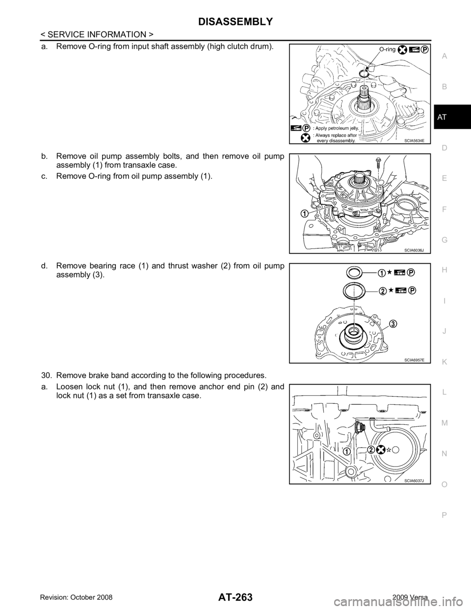
a. Remove O-ring from input shaft assembly (high clutch drum).
b. Remove oil pump assembly bolts, and then remove oil pump assembly (1) from transaxle case.
c. Remove O-ring from oil pump assembly (1).
d. Remove bearing race (1) and thrust washer (2) from oil pump assembly (3).
30. Remove brake band according to the following procedures.
a. Loosen lock nut (1), and then remove anchor end pin (2) and lock nut (1) as a set from transaxle case.