check engine NISSAN LATIO 2009 Service Repair Manual
[x] Cancel search | Manufacturer: NISSAN, Model Year: 2009, Model line: LATIO, Model: NISSAN LATIO 2009Pages: 4331, PDF Size: 58.04 MB
Page 2988 of 4331
EM
NP
O
Inspection
INFOID:0000000004784291
INSPECTION AFTER INSTALLATION 1. Check the engine oil level and adjust as necessary. Refer to LU-7, " Inspection " .
2. Start engine, and check there are no leaks of engine oil.
3. Stop engine and wait for 10 minutes.
4. Check the engine oil level again. Refer to LU-7, " Inspection " .
Page 2992 of 4331
EM
NP
O
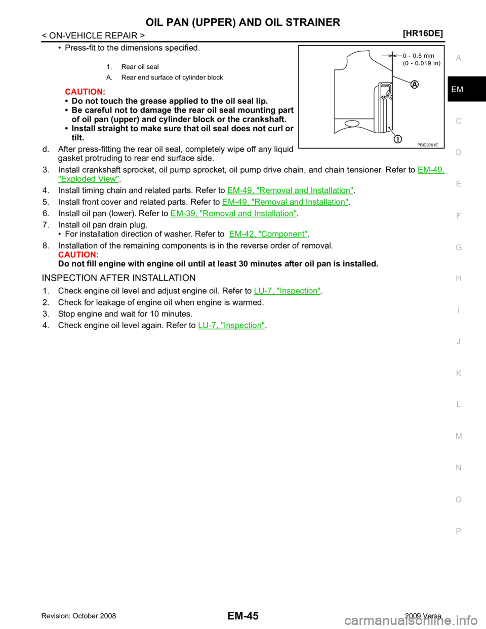
• Press-fit to the dimensions specified.
CAUTION:
• Do not touch the grease applied to the oil seal lip.
• Be careful not to damage the rear oil seal mounting part of oil pan (upper) and cylinder block or the crankshaft.
• Install straight to make sure that oil seal does not curl or tilt.
d. After press-fitting the rear oil seal, completely wipe off any liquid gasket protruding to rear end surface side.
3. Install crankshaft sprocket, oil pump sprocket, oi l pump drive chain, and chain tensioner. Refer to EM-49," Exploded View " .
4. Install timing chain and related parts. Refer to EM-49, " Removal and Installation " .
5. Install front cover and related parts. Refer to EM-49, " Removal and Installation " .
6. Install oil pan (lower). Refer to EM-39, " Removal and Installation " .
7. Install oil pan drain plug. • For installation direction of washer. Refer to EM-42, " Component " .
8. Installation of the remaining components is in the reverse order of removal. CAUTION:
Do not fill engine with engi ne oil until at least 30 minutes after oil pan is installed.
INSPECTION AFTER INSTALLATION 1. Check engine oil level and adjust engine oil. Refer to LU-7, " Inspection " .
2. Check for leakage of engine oil when engine is warmed.
3. Stop engine and wait for 10 minutes.
4. Check engine oil level again. Refer to LU-7, " Inspection " .
1. Rear oil seal
A. Rear end surface of cylinder block
Page 2994 of 4331
EM
NP
O
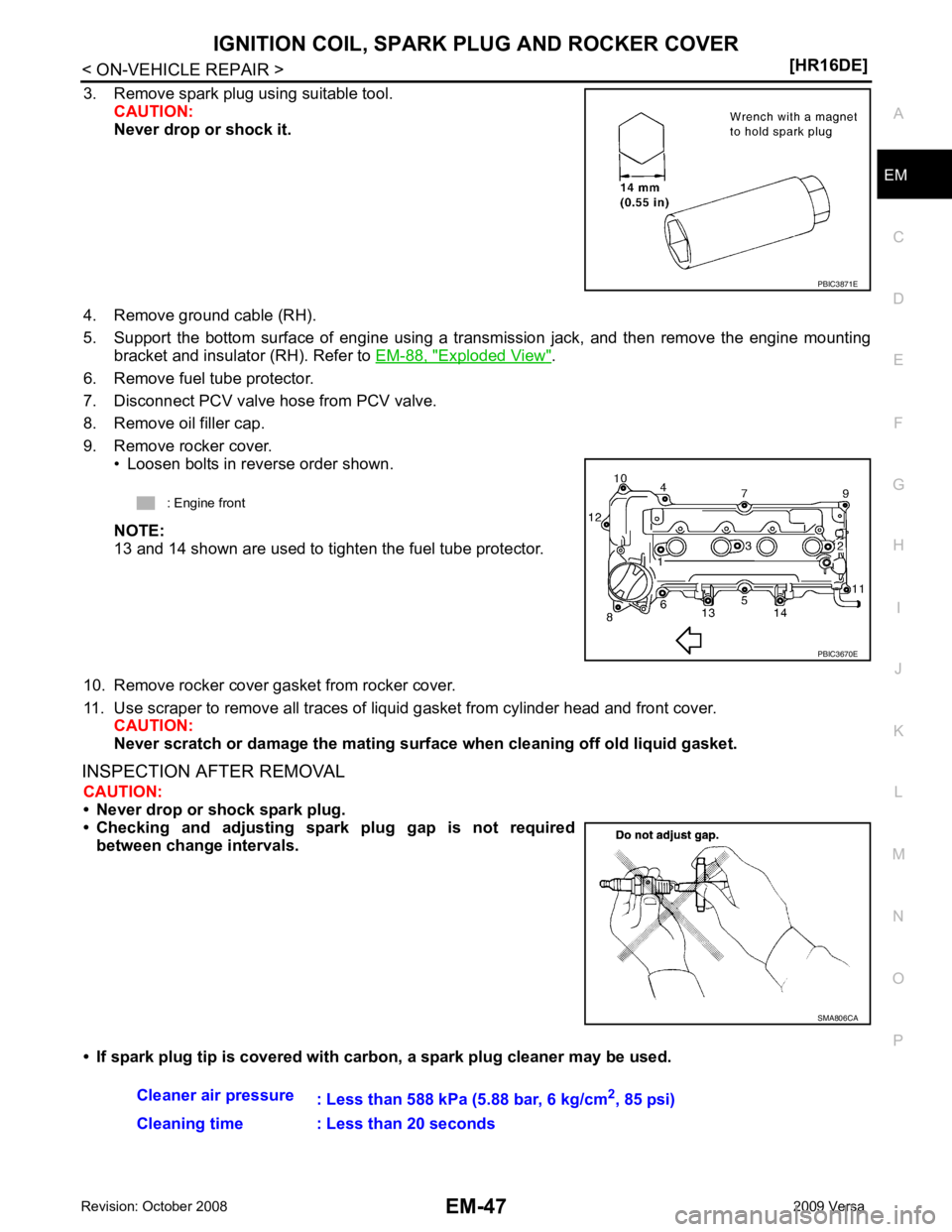
3. Remove spark plug using suitable tool.
CAUTION:
Never drop or shock it.
4. Remove ground cable (RH).
5. Support the bottom surface of engine using a trans mission jack, and then remove the engine mounting
bracket and insulator (RH). Refer to EM-88, " Exploded View " .
6. Remove fuel tube protector.
7. Disconnect PCV valve hose from PCV valve.
8. Remove oil filler cap.
9. Remove rocker cover. • Loosen bolts in reverse order shown.
NOTE:
13 and 14 shown are used to tighten the fuel tube protector.
10. Remove rocker cover gasket from rocker cover.
11. Use scraper to remove all traces of liquid gasket from cylinder head and front cover.
CAUTION:
Never scratch or damage the mating su rface when cleaning off old liquid gasket.
INSPECTION AFTER REMOVAL CAUTION:
• Never drop or shock spark plug.
• Checking and adjusting spar k plug gap is not required
between change intervals.
• If spark plug tip is covered with carbon, a spark plug cleaner may be used. SMA806CA
Page 3003 of 4331
![NISSAN LATIO 2009 Service Repair Manual EM-56< ON-VEHICLE REPAIR >
[HR16DE]
TIMING CHAIN
c. Tighten bolts in the numerical order shown.
d. After all bolts are tightened, retighten them to specified torque in numerical order as shown.
CAUTIO NISSAN LATIO 2009 Service Repair Manual EM-56< ON-VEHICLE REPAIR >
[HR16DE]
TIMING CHAIN
c. Tighten bolts in the numerical order shown.
d. After all bolts are tightened, retighten them to specified torque in numerical order as shown.
CAUTIO](/img/5/57359/w960_57359-3002.png)
EM-56< ON-VEHICLE REPAIR >
[HR16DE]
TIMING CHAIN
c. Tighten bolts in the numerical order shown.
d. After all bolts are tightened, retighten them to specified torque in numerical order as shown.
CAUTION:
Be sure to wipe off any excessive liquid gasket leaking to
surface.
8. Insert crankshaft pulley by aligning with crankshaft key. • When inserting crankshaft pulley with a plastic hamme r, tap on its center portion (not circumference).
CAUTION:
Never damage front oil seal lip section.
9. Tighten crankshaft pulley bolt with the following procedure: • Secure crankshaft pulley with a suitable tool, and tighten crankshaft pulley bolt.
a. Apply new engine oil to thread and seat surfaces of crankshaft pulley bolt.
b. Tighten crankshaft pulley bolt.
c. Put a paint mark (B) on crankshaft pulley, mating with any one of six easy to recognize angle marks (A) on crankshaft bolt flange
(1).
d. Turn another 60 degrees clockwise (angle tightening). • Check the tightening angle with movement of one angle mark.
10. Make sure that crankshaft turns smoothly by rotating by hand clockwise.
11. Installation of the remaining components is in the reverse order of removal.
Inspection INFOID:0000000004784298
INSPECTION AFTER REMOVAL
Timing Chain KBIA3429J
Crankshaft pulley bolt : 35.0 N·m (3.6 kg-m, 26 ft-lb)
PBIC3726E
Page 3004 of 4331
EM
NP
O
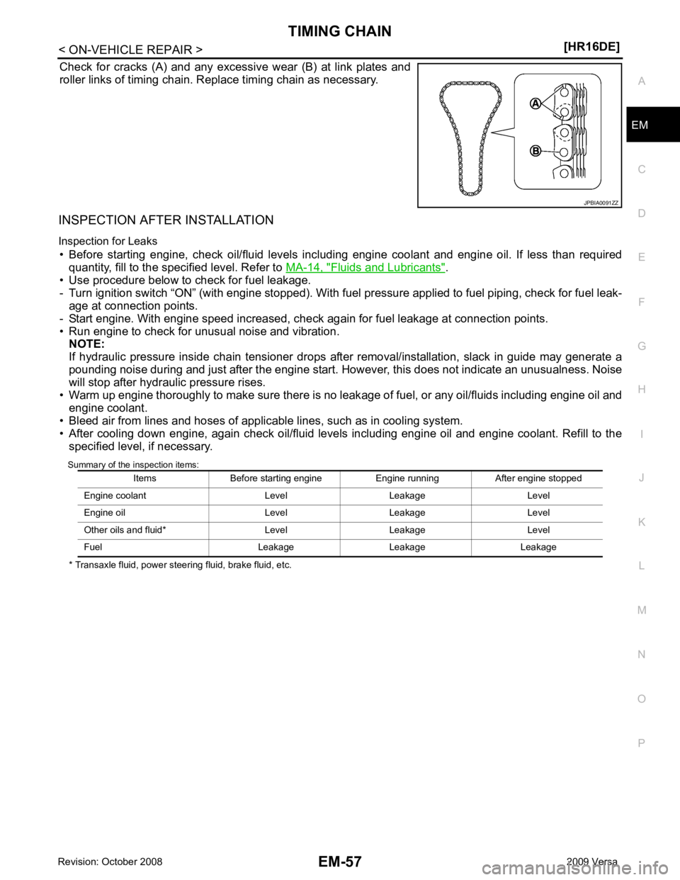
Check for cracks (A) and any excessive wear (B) at link plates and
roller links of timing chain. Replace timing chain as necessary.
INSPECTION AFTER INSTALLATION
Inspection for Leaks • Before starting engine, check oil/fluid levels incl uding engine coolant and engine oil. If less than required
quantity, fill to the specified level. Refer to MA-14, " Fluids and Lubricants " .
• Use procedure below to check for fuel leakage.
- Turn ignition switch “ON” (with engine stopped). With fuel pressure applied to fuel piping, check for fuel leak-
age at connection points.
- Start engine. With engine speed increased, check again for fuel leakage at connection points.
• Run engine to check for unusual noise and vibration. NOTE:
If hydraulic pressure inside chain tensioner drops after removal/installation, slack in guide may generate a
pounding noise during and just after the engine start. However, this does not indicate an unusualness. Noise
will stop after hydraulic pressure rises.
• Warm up engine thoroughly to make sure there is no leak age of fuel, or any oil/fluids including engine oil and
engine coolant.
• Bleed air from lines and hoses of applicable lines, such as in cooling system.
• After cooling down engine, again check oil/fluid levels including engine oil and engine coolant. Refill to the specified level, if necessary.
Summary of the inspection items:
* Transaxle fluid, power steering fluid, brake fluid, etc.
Page 3017 of 4331
![NISSAN LATIO 2009 Service Repair Manual EM-70< ON-VEHICLE REPAIR >
[HR16DE]
CAMSHAFT
c. Tighten bolts in the numerical order shown.
d. After all bolts are tightened, retighten them to specified torque in numerical order as shown.
CAUTION:
B NISSAN LATIO 2009 Service Repair Manual EM-70< ON-VEHICLE REPAIR >
[HR16DE]
CAMSHAFT
c. Tighten bolts in the numerical order shown.
d. After all bolts are tightened, retighten them to specified torque in numerical order as shown.
CAUTION:
B](/img/5/57359/w960_57359-3016.png)
EM-70< ON-VEHICLE REPAIR >
[HR16DE]
CAMSHAFT
c. Tighten bolts in the numerical order shown.
d. After all bolts are tightened, retighten them to specified torque in numerical order as shown.
CAUTION:
Be sure to wipe off any excessive liquid gasket leaking to
surface.
22. Insert crankshaft pulley by aligning with crankshaft key. • When inserting crankshaft pulley with a plastic hamme r, tap on its center portion (not circumference).
CAUTION:
Never damage front oil seal lip section.
23. Tighten crankshaft pulley bolt with the following procedure: • Secure crankshaft pulley with a suitable tool, and tighten crankshaft pulley bolt.
a. Apply new engine oil to thread and seat surfaces of crankshaft pulley bolt.
b. Tighten crankshaft pulley bolt.
c. Put a paint mark (B) on crankshaft pulley, mating with any one of six easy to recognize angle marks (A) on crankshaft bolt flange
(1).
d. Turn another 60 degrees clockwise (angle tightening). • Check the tightening angle with movement of one angle mark.
24. Make sure that crankshaft turns smoothly by rotating by hand clockwise.
25. Install the camshaft position sensor (PHASE) to the rear end of cylinder head.
• Tighten bolts with it seated completely.
26. Check and adjust valve clearance. Refer to EM-20, " Inspection and Adjustment " .
27. Installation of the remaining components is in the reverse order of removal.
Inspection INFOID:0000000004784301
INSPECTION AFTER REMOVAL
Oil Filter KBIA3429J
Crankshaft pulley bolt : 35.0 N·m (3.6 kg-m, 26 ft-lb)
PBIC3726E
Page 3021 of 4331
Fluids and Lubricants " .
• Use procedure below to check for fuel leakage.
- Turn ignition switch “ON” (with engine stopped). With fuel pressure applied to fuel piping, check for fuel leak-
age at connection points.
- Start engine. With engine speed increased, che ck again for fuel leakage at connection points.
• Run engine to check for unusual noise and vibration. NOTE:
If hydraulic pressure inside timing chain tensioner drops after removal/installation, slack in the guide may
generate a pounding noise during and just after engine start. However, this is normal. Noise will stop after
hydraulic pressure rises.
• Warm up engine thoroughly to make sure there is no leakage of fuel, or any oil/fluids including engine oil and
engine coolant.
• Bleed air from lines and hoses of applicable lines, such as in cooling system.
• After cooling down engine, again check oil/fluid levels including engine oil and engine coolant. Refill to the
specified level, if necessary.
Summary of the inspection items:
*: Transmission/transaxle/CVT fluid, power steering fluid, brake fluid, etc.
Inspection of Camshaft Sprocket (INT) Oil Groove
CAUTION:
• Perform this inspection only when DTC P0011 is de tected in self-diagnostic results of CONSULT-III
and it is directed according to inspect ion procedure of EC section. Refer to EC-133, " Diagnosis Pro-
cedure " .
• Check when engine is cold so as to pr event burns from the splashing engine oil.
1. Check engine oil level. Refer to LU-7, " Inspection " .
2. Perform the following procedure so as to prevent the engine from being unintentionally started while
checking.
a. Release the fuel pressure. Refer to EC-498, " Inspection " .
b. Remove intake manifold. Refer to EM-28, " Exploded View " .
c. Disconnect ignition coil and injector harness connectors. Refer to EM-46, " Exploded View " .
3. Remove intake valve timing control solenoid valve. Refer to EM-49, " Exploded View " .
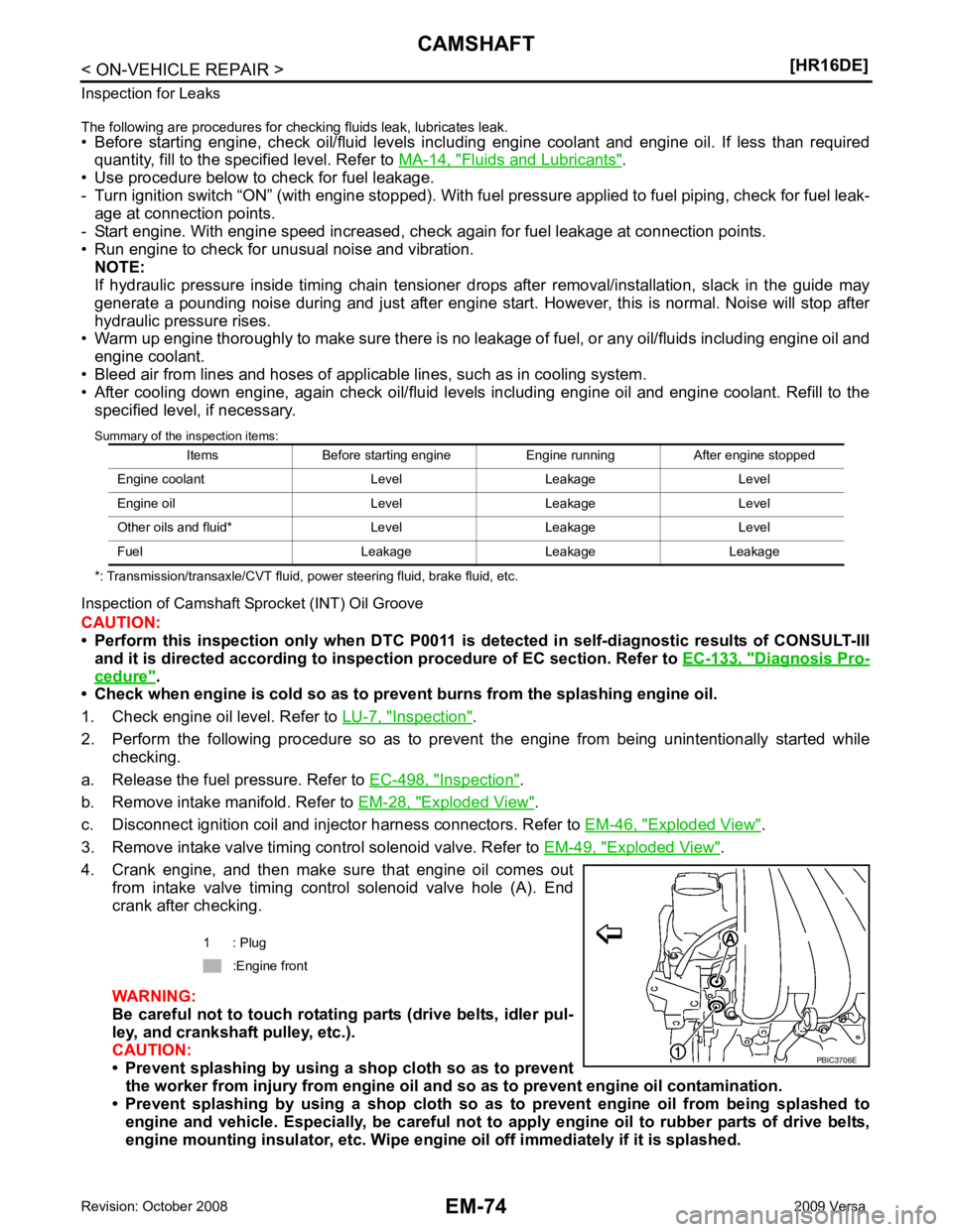
4. Crank engine, and then make sure that engine oil comes out from intake valve timing control solenoid valve hole (A). End
crank after checking.
WARNING:
Be careful not to touch rotating parts (drive belts, idler pul-
ley, and crankshaft pulley, etc.).
CAUTION:
• Prevent splashing by using a shop cloth so as to prevent
the worker from injury from engine oil an d so as to prevent engine oil contamination.
• Prevent splashing by using a shop cloth so as to prevent engine oil from being splashed to
engine and vehicle. Especially, be careful not to apply engine oil to rubber parts of drive belts,
engine mounting insulator, etc. Wipe engi ne oil off immediately if it is splashed.
Items Before starting engine Engine running After engine stopped
Engine coolant Level Leakage Level
Engine oil Level Leakage Level
Other oils and fluid* Level Leakage Level
Fuel Leakage Leakage Leakage 1 : Plug
:Engine front
Page 3022 of 4331
EM
NP
O
5. Perform the following inspection if engine oil does not
come out from intake valve timing control solenoid
valve oil hole of the cylinder head.
• Remove oil filter, and then clean it. Refer to EM-70, " Inspection " .
• Clean oil groove between oil strainer and intake valve timing control solenoid valve. Refer to LU-6," Engine Lubrication System " and
LU-6, " Engine Lubrication System Schematic " .
6. Remove components between intake valve timing control solenoid valve and camshaft sprocket (INT), and then check each oil groove for clogging.
• Clean oil groove if necessary. Refer to LU-6, " Engine Lubrication System " and
LU-6, " Engine Lubrica-
tion System Schematic " .
7. After inspection, installation is in the reverse order of removal.
Page 3028 of 4331
![NISSAN LATIO 2009 Service Repair Manual CYLINDER HEAD
EM-81
< ON-VEHICLE REPAIR >
[HR16DE] C
D E
F
G H
I
J
K L
M A EM
NP
O
2. Tighten cylinder head bolts in numer
ical order as shown with the
following procedure to install cylinder head.
CA NISSAN LATIO 2009 Service Repair Manual CYLINDER HEAD
EM-81
< ON-VEHICLE REPAIR >
[HR16DE] C
D E
F
G H
I
J
K L
M A EM
NP
O
2. Tighten cylinder head bolts in numer
ical order as shown with the
following procedure to install cylinder head.
CA](/img/5/57359/w960_57359-3027.png)
CYLINDER HEAD
EM-81
< ON-VEHICLE REPAIR >
[HR16DE] C
D E
F
G H
I
J
K L
M A EM
NP
O
2. Tighten cylinder head bolts in numer
ical order as shown with the
following procedure to install cylinder head.
CAUTION:
If cylinder head bolts are re -used, check their outer diame-
ters before installation. Fol low the “Cylinder Head Bolts
Outer Diameter” measurement procedure.
a. Apply new engine oil to threads and seating surfaces of bolts.
b. Tighten all bolts in the specified order.
c. Turn all bolts 60 degrees clockwise (angle tightening) using Tool (A) in the specified order.
CAUTION:
Check and confirm the tightening angle by using Tool (A) or
protractor. Avoid judgment by visual inspection without the
tool.
d. Completely loosen all bolts in reverse order. CAUTION:
In this step, loosen bolts in reverse order of that indicated.
e. Tighten all bolts in the specified order.
f. Turn all bolts 75 degrees clockwise (angle tightening) using Tool (A) in the specified order.
CAUTION:
Check and confirm the tightening angle by using Tool (A) or
protractor. Avoid judgment by visual inspection without the
tool.
g. Turn all bolts 75 degrees clockwise again (angle tightening) using Tool (A) in the specified order.
CAUTION:
Check and confirm the tightening angle by using To ol (A) or protractor. Avoid judgment by visual
inspection without the tool.
3. Installation of the remaining components is in the reverse order of removal.
INSPECTION AFTER INSTALLATION
Inspection for Leaks • Before starting engine, check oil/fluid levels incl uding engine coolant and engine oil. If less than required
quantity, fill to the specified level. Refer to MA-14, " Fluids and Lubricants " .
A : EXH side
B : INT side
: Engine front
: 40.0 N·m (4.1 kg-m, 30 ft-lb)
Tool number : KV10112100 (BT-8653-A) PBIC3732E
PBIC3733E
: 0 N·m (0 kg-m, 0 ft-lb)
: 40.0 N·m (4.1 kg-m, 30 ft-lb)
Tool number : KV10112100 (BT-8653-A) PBIC3733E
Page 3038 of 4331
EM
NP
O
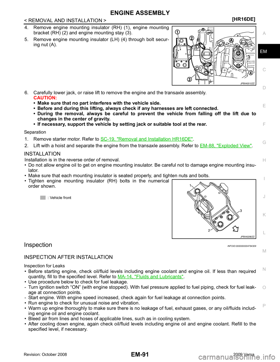
4. Remove engine mounting insulator (RH) (1), engine mounting
bracket (RH) (2) and engine mounting stay (3).
5. Remove engine mounting insulator (LH) (4) through bolt secur- ing nut (A).
6. Carefully lower jack, or raise lift to remove the engine and the transaxle assembly. CAUTION:
• Make sure that no part interferes with the vehicle side.
• Before and during this lifting, alw ays check if any harnesses are left connected.
• During the removal, always be careful to prevent the vehicle from falling off the lift due to
changes in the center of gravity.
• If necessary, support the vehicle by setting jack or suitable tool at the rear.
Separation 1. Remove starter motor. Refer to SC-19, " Removal and Installation HR16DE " .
2. Lift with a hoist and separate the engine from the transaxle assembly. Refer to EM-88, " Exploded View " .
INSTALLATION Installation is in the reverse order of removal.
• Do not allow engine oil to get on engine mounting insulator. Be careful not to damage engine mounting insu- lator.
• Make sure that each mounting insulator is seated properly, and tighten nuts and bolts.
• Tighten engine mounting insulator (RH) bolts in the numerical
order shown.
Inspection INFOID:0000000004784309
INSPECTION AFTER INSTALLATION
Inspection for Leaks • Before starting engine, check oil/fluid levels incl uding engine coolant and engine oil. If less than required
quantity, fill to the specified level. Refer to MA-14, " Fluids and Lubricants " .
• Use procedure below to check for fuel leakage.
- Turn ignition switch “ON” (with engine stopped). With fuel pressure applied to fuel piping, check for fuel leak-
age at connection points.
- Start engine. With engine speed increased, check again for fuel leakage at connection points.
• Run engine to check for unusual noise and vibration.
• Warm up engine thoroughly to make sure there is no leak age of fuel, exhaust gases, or any oil/fluids includ-
ing engine oil and engine coolant.
• Bleed air from lines and hoses of applicable lines, such as in cooling system.
• After cooling down engine, again check oil/fluid levels including engine oil and engine coolant. Refill to the specified level, if necessary.