oil type NISSAN LATIO 2009 Service Repair Manual
[x] Cancel search | Manufacturer: NISSAN, Model Year: 2009, Model line: LATIO, Model: NISSAN LATIO 2009Pages: 4331, PDF Size: 58.04 MB
Page 24 of 4331
A/T FLUID
AT-19
< SERVICE INFORMATION >
D
E
F
G H
I
J
K L
M A
B AT
N
O P
13. Flush each steel line from the cooler side back to
ward the A/T by spraying Transmission Cooler Cleaner
in a continuous stream for 5 seconds.
14. Blow compressed air regulated to 5 - 9 kg/cm 2
(71 - 128 psi) through each steel line from the cooler side
back toward the A/T for 10 seconds to force out any remaining A/T fluid.
15. Ensure all debris is removed from the steel cooler lines.
16. Ensure all debris is removed from the banjo bolts and fittings.
17. Perform "A/T FLUID COOL ER DIAGNOSIS PROCEDURE".
A/T FLUID COOLER DIAGNOSIS PROCEDURE NOTE:
Insufficient cleaning of the cooler inlet hose exte rior may lead to inaccurate debris identification.
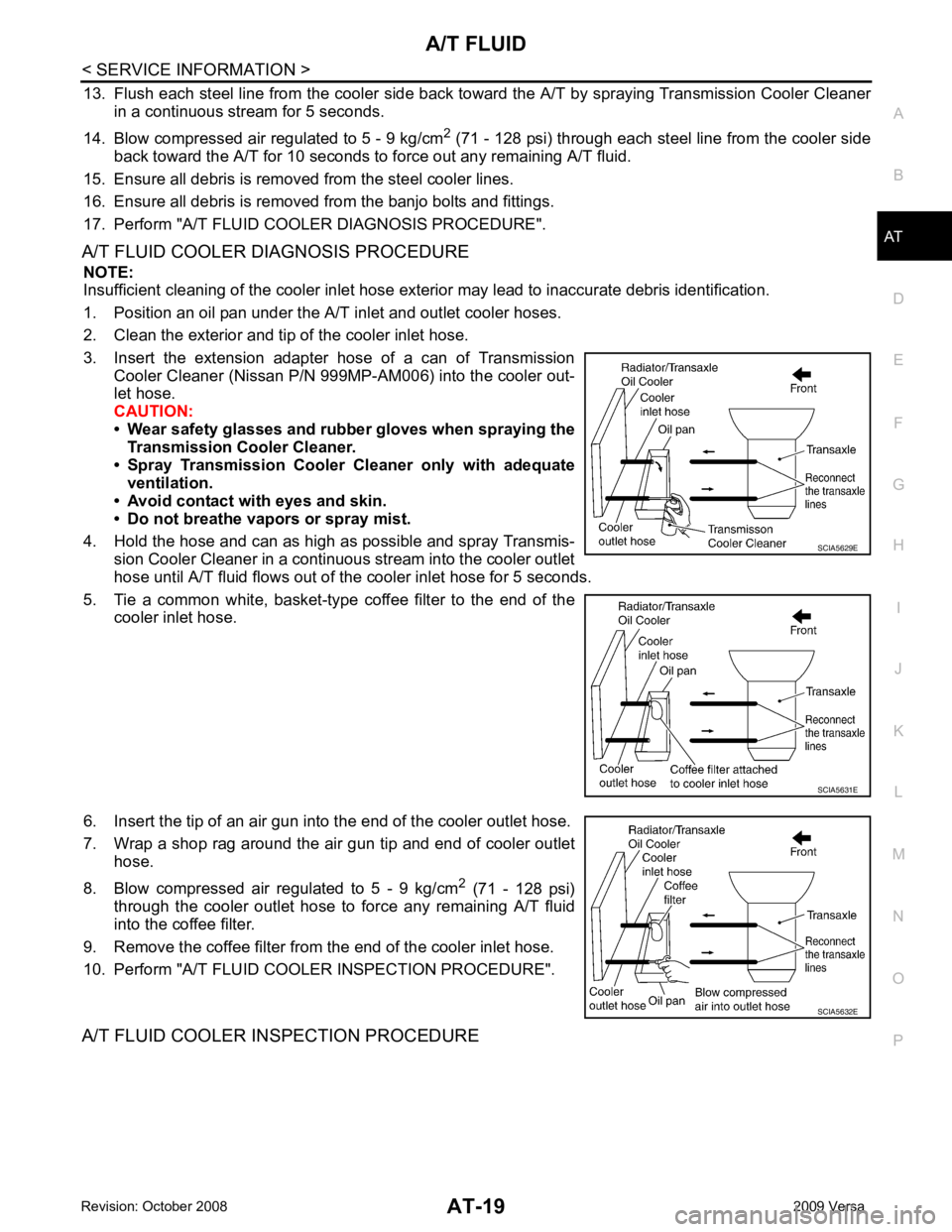
1. Position an oil pan under the A/T inlet and outlet cooler hoses.
2. Clean the exterior and tip of the cooler inlet hose.
3. Insert the extension adapter hose of a can of Transmission Cooler Cleaner (Nissan P/N 999MP-AM006) into the cooler out-
let hose.
CAUTION:
• Wear safety glasses and rubber gloves when spraying the
Transmission Cooler Cleaner.
• Spray Transmission Cooler Cleaner only with adequate
ventilation.
• Avoid contact with eyes and skin.
• Do not breathe vapors or spray mist.
4. Hold the hose and can as high as possible and spray Transmis- sion Cooler Cleaner in a continuous stream into the cooler outlet
hose until A/T fluid flows out of t he cooler inlet hose for 5 seconds.
5. Tie a common white, basket-type coffee filter to the end of the cooler inlet hose.
6. Insert the tip of an air gun into the end of the cooler outlet hose.
7. Wrap a shop rag around the air gun tip and end of cooler outlet hose.
8. Blow compressed air regulated to 5 - 9 kg/cm 2
(71 - 128 psi)
through the cooler outlet hose to force any remaining A/T fluid
into the coffee filter.
9. Remove the coffee filter from the end of the cooler inlet hose.
10. Perform "A/T FLUID COOL ER INSPECTION PROCEDURE".
A/T FLUID COOLER INSPECTION PROCEDURE SCIA5629E
SCIA5631E
SCIA5632E
Page 76 of 4331
AT
N
O P
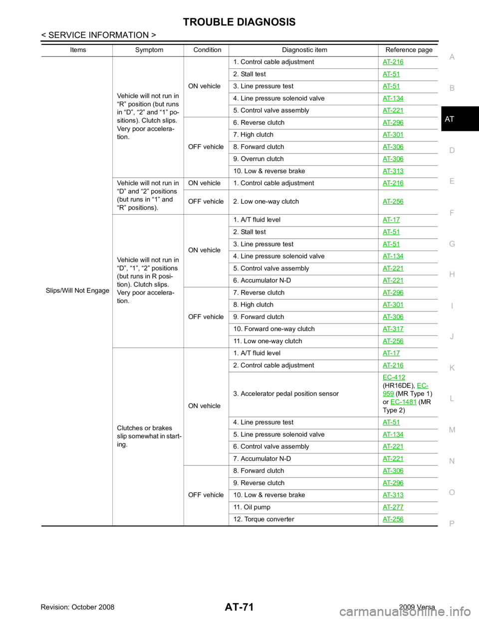
Slips/Will Not Engage
Vehicle will not run in
“R” position (but runs
in “D”, “2” and “1” po-
sitions). Clutch slips.
Very poor accelera-
tion. ON vehicle
1. Control cable adjustment
AT-216 2. Stall test
AT-51 3. Line pressure test
AT-51 4. Line pressure solenoid valve
AT-134 5. Control valve assembly
AT-221 OFF vehicle
6. Reverse clutch
AT-296 7. High clutch
AT-301 8. Forward clutch
AT-306 9. Overrun clutch
AT-306 10. Low & reverse brake
AT-313Vehicle will not run in
“D” and “2” positions
(but runs in “1” and
“R” positions). ON vehicle 1. Control cable adjustment
AT-216OFF vehicle 2. Low one-way clutch
AT-256Vehicle will not run in
“D”, “1”, “2” positions
(but runs in R posi-
tion). Clutch slips.
Very poor accelera-
tion. ON vehicle
1. A/T fluid level
AT-17 2. Stall test
AT-51 3. Line pressure test
AT-51 4. Line pressure solenoid valve
AT-134 5. Control valve assembly
AT-221 6. Accumulator N-D
AT-221 OFF vehicle
7. Reverse clutch
AT-296 8. High clutch
AT-301 9. Forward clutch
AT-306 10. Forward one-way clutch
AT-317 11. Low one-way clutch
AT-256Clutches or brakes
slip somewhat in start-
ing. ON vehicle1. A/T fluid level
AT-17 2. Control cable adjustment
AT-216 3. Accelerator pedal position sensor
EC-412
(HR16DE), EC- 959 (MR Type 1)
or EC-1481 (MR
Type 2)
4. Line pressure test AT-51 5. Line pressure solenoid valve
AT-134 6. Control valve assembly
AT-221 7. Accumulator N-D
AT-221 OFF vehicle
8. Forward clutch
AT-306 9. Reverse clutch
AT-296 10. Low & reverse brake
AT-313 11. Oil pump
AT-277 12. Torque converter
AT-256Items Symptom Condition Diagnostic item Reference page
Page 77 of 4331

,
AT-187 ON vehicle
1. A/T fluid level
AT-17 2. Line pressure test
AT-51 3. Control valve assembly
AT-221 OFF vehicle
4. Forward clutch
AT-306 5. Oil pump
AT-277 6. Torque converter
AT-256Almost no shock or
clutches slipping in
change from D 1 to D 2
. ON vehicle1. A/T fluid level
AT-17 2. Accelerator pedal position sensor
EC-412
(HR16DE), EC- 959 (MR Type 1)
or EC-1481 (MR
Type 2)
3. Line pressure test AT-51 4. Accumulator servo release
AT-221 5. Control valve assembly
AT-221 OFF vehicle 6. Brake band
AT-330Almost no shock or
slipping in changing
from D 2 to D 3 . ON vehicle 1. A/T fluid level
AT-17 2. Accelerator pedal position sensor
EC-412
(HR16DE), EC- 959 (MR Type 1)
or EC-1481 (MR
Type 2)
3. Line pressure test AT-51 4. Control valve assembly
AT-221 OFF vehicle
5. High clutch
AT-301 6. Forward clutch
AT-306Almost no shock or
slipping in changing
from D 3 to D 4 . ON vehicle 1. A/T fluid level
AT-17 2. Accelerator pedal position sensor
EC-412
(HR16DE), EC- 959 (MR Type 1)
or EC-1481 (MR
Type 2)
3. Line pressure test AT-51 4. Control valve assembly
AT-221 OFF vehicle 5. Brake band
AT-330Races extremely fast
or slips in changing
from D 4 to D 3 when
depressing accelera-
tor pedal. ON vehicle1. A/T fluid level
AT-17 2. Accelerator pedal position sensor
EC-412
(HR16DE), EC- 959 (MR Type 1)
or EC-1481 (MR
Type 2)
3. Line pressure test AT-51 4. Line pressure solenoid valve
AT-134 5. Shift solenoid valve A
AT-139 6. Control valve assembly
AT-221 OFF vehicle
7. Brake band
AT-330 8. Forward clutch
AT-306Races extremel y
ON hi l 2. Accelerator pedal position sensor
EC-412
(HR16DE), EC- 959 (MR Type 1)
or EC-1481 (MR
Type 2)
Items Symptom Condition Diagnostic item Reference page
Page 78 of 4331
AT
N
O P
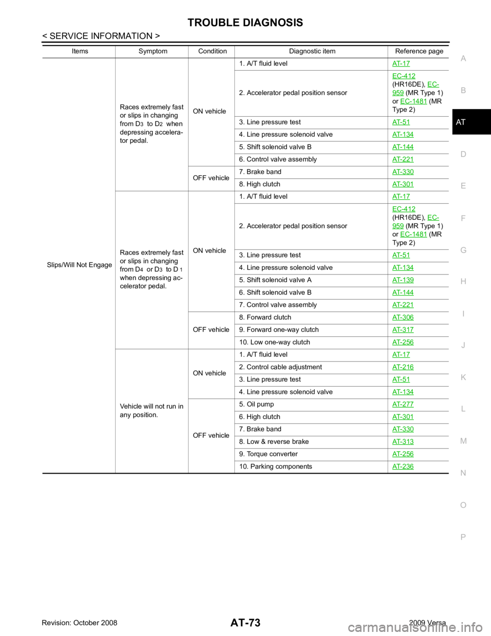
Slips/Will Not Engage
Races extremely fast
or slips in changing
from D 3 to D 2 when
depressing accelera-
tor pedal. ON vehicle1. A/T fluid level
AT-17 2. Accelerator pedal position sensor
EC-412
(HR16DE), EC- 959 (MR Type 1)
or EC-1481 (MR
Type 2)
3. Line pressure test AT-51 4. Line pressure solenoid valve
AT-134 5. Shift solenoid valve B
AT-144 6. Control valve assembly
AT-221 OFF vehicle
7. Brake band
AT-330 8. High clutch
AT-301Races extremely fast
or slips in changing
from D 4 or D 3 to D 1
when depressing ac-
celerator pedal. ON vehicle1. A/T fluid level
AT-17 2. Accelerator pedal position sensor
EC-412
(HR16DE), EC- 959 (MR Type 1)
or EC-1481 (MR
Type 2)
3. Line pressure test AT-51 4. Line pressure solenoid valve
AT-134 5. Shift solenoid valve A
AT-139 6. Shift solenoid valve B
AT-144 7. Control valve assembly
AT-221 OFF vehicle
8. Forward clutch
AT-306 9. Forward one-way clutch
AT-317 10. Low one-way clutch
AT-256Vehicle will not run in
any position. ON vehicle
1. A/T fluid level
AT-17 2. Control cable adjustment
AT-216 3. Line pressure test
AT-51 4. Line pressure solenoid valve
AT-134 OFF vehicle
5. Oil pump
AT-277 6. High clutch
AT-301 7. Brake band
AT-330 8. Low & reverse brake
AT-313 9. Torque converter
AT-256 10. Parking components
AT-236Items Symptom Condition Diagnostic item Reference page
Page 79 of 4331

ON vehicle
1. Ignition switch and starter
PG-3 ,
SC-9 2. Control cable adjustment
AT-216 3. PNP switch adjustment
AT-224Engine starts in posi-
tions other than “P”
and “N”. ON vehicle
1. Control cable adjustment
AT-216 2. PNP switch adjustment
AT-224Transaxle noise in“ P”
and “N” positions. ON vehicle1. A/T fluid level
AT-17 2. Line pressure test
AT-51 3. Accelerator pedal position sensor
EC-412
(HR16DE), EC- 959 (MR Type 1)
or EC-1481 (MR
Type 2)
4. Vehicle speed sensor·A/T (Revolution sensor)
and vehicle speed sensor·MTR AT-101 ,
AT-154 OFF vehicle
5. Oil pump
AT-277 6. Torque converter
AT-256Items Symptom Condition Diagnostic item Reference page
Page 81 of 4331

2. PNP switch adjustment
AT-224 3. Overdrive control switch
AT-172 4. Accelerator pedal position sensor
EC-412
(HR16DE), EC- 959 (MR Type 1)
or EC-1481 (MR
Type 2)
5. Vehicle speed sensor·A/T (Revolution sensor)
and vehicle speed sensor·MTR AT-101 ,
AT-154 6. Shift solenoid valve A
AT-139 7. Shift solenoid valve B
AT-144 8. Control valve assembly
AT-221 OFF vehicle
9. Reverse clutch
AT-296 10. High clutch
AT-301 11. Brake band
AT-330 12. Low & reverse brake
AT-313 13. Oil pump
AT-277 14. Torque converter
AT-256Transaxle noise in
“D”, “2”, “1” and “R”
positions. ON vehicle 1. A/T fluid level
AT-17OFF vehicle 2. Torque converter
AT-256Engine brake does
not operate in “1” po-
sition. ON vehicle1. PNP switch adjustment
AT-224 2. Control cable adjustment
AT-216 3. Vehicle speed sensor·A/T (Revolution sensor)
and vehicle speed sensor·MTR AT-101 ,
AT-154 4. Control valve assembly
AT-221 5. Overrun clutch solenoid valve
AT-149 OFF vehicle
6. Overrun clutch
AT-306 7. Low & reverse brake
AT-313Transaxle overheats.
ON vehicle1. A/T fluid level
AT-17 2. Engine idling speed
EC-30
(HR16DE), EC- 570 (MR Type 1)
or EC-1082 (MR
Type 2)
3. Accelerator pedal position sensor EC-412
(HR16DE), EC- 959 (MR Type 1)
or EC-1481 (MR
Type 2)
4. Line pressure test AT-51 5. Line pressure solenoid valve
AT-134 6. Control valve assembly
AT-221 OFF vehicle
7. Oil pump
AT-277 8. Reverse clutch
AT-296 9. High clutch
AT-301 10. Brake band
AT-330 11. Forward clutch
AT-306 12. Overrun clutch
AT-306Items Symptom Condition Diagnostic item Reference page
Page 194 of 4331
AT
N
O P
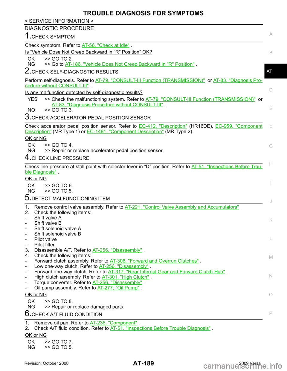
DIAGNOSTIC PROCEDURE Check at Idle " .
Is “ Vehicle Dose Not Creep Backward in “ R ” Position ” OK?
OK >> GO TO 2.
NG >> Go to AT-186, " Vehicle Does Not Creep Backward in "R" Position " .
CONSULT-III Functi
on (TRANSMISSION) " or
AT-83, " Diagnosis Pro-
cedure without CONSULT-III " .
Is any malfunction detected by self-diagnostic results? YES >> Check the malfuncti
oning system. Refer to AT-79, " CONSULT-III Functi
on (TRANSMISSION) " or
AT-83, " Diagnosis Procedure without CONSULT-III " .
NO >> GO TO 3. Description " (HR16DE),
EC-959, " Component
Description " (MR Type 1) or
EC-1481, " Component Description " (MR Type 2).
OK or NG OK >> GO TO 4.
NG >> Repair or replace accelerator pedal position sensor. Inspections Before Trou-
ble Diagnosis " .
OK or NG OK >> GO TO 6.
NG >> GO TO 5. Control Valve Assembly and Accumulators " .
2. Check the following items:
- Shift valve A
- Shift valve B
- Shift solenoid valve A
- Shift solenoid valve B
- Pilot valve
- Pilot filter
3. Disassemble A/T. Refer to AT-256, " Disassembly " .
4. Check the following items:
- Forward clutch assembly. Refer to AT-306, " Forward and Overrun Clutches " .
- Low one-way clutch. Refer to AT-256, " Disassembly " .
- Forward one-way clutch. Refer to AT-317, " Rear Internal Gear and Forward Clutch Hub " .
- High clutch assembly. Refer to AT-301, " High Clutch " .
- Torque converter. Refer to AT-256, " Disassembly " .
- Oil pump assembly. Refer to AT-277, " Oil Pump " .
OK or NG OK >> GO TO 8.
NG >> Repair or replace damaged parts. Component " .
2. Check A/T fluid condition. Refer to AT-51, " Inspections Before Trouble Diagnosis " .
OK or NG OK >> GO TO 7.
NG >> GO TO 5.
Page 197 of 4331
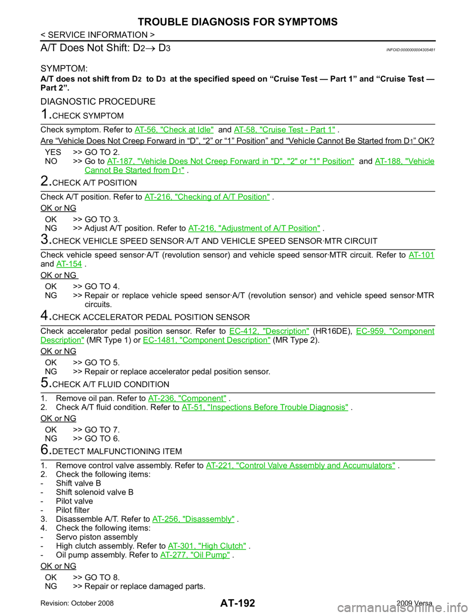
Check at Idle " and
AT-58, " Cruise Test - Part 1 " .
Are “ Vehicle Does Not Creep Forward in “ D ” , “ 2 ” or “ 1 ” Position ” and “ Vehicle Cannot Be Started from D OK?
YES >> GO TO 2.
NO >> Go to AT-187, " Vehicle Does Not Creep Forward in "D", "2" or "1" Position " and
AT-188, " Vehicle
Cannot Be Started from D .
Checking of A/T Position " .
OK or NG OK >> GO TO 3.
NG >> Adjust A/T position. Refer to AT-216, " Adjustment of A/T Position " .
and
AT-154 .
OK or NG OK >> GO TO 4.
NG >> Repair or replace vehicle speed sensor·A/T (revolution sensor) and vehicle speed sensor·MTR circuits. Description " (HR16DE),
EC-959, " Component
Description " (MR Type 1) or
EC-1481, " Component Description " (MR Type 2).
OK or NG OK >> GO TO 5.
NG >> Repair or replace accelerator pedal position sensor. Component " .
2. Check A/T fluid condition. Refer to AT-51, " Inspections Before Trouble Diagnosis " .
OK or NG OK >> GO TO 7.
NG >> GO TO 6. Control Valve Assembly and Accumulators " .
2. Check the following items:
- Shift valve B
- Shift solenoid valve B
- Pilot valve
- Pilot filter
3. Disassemble A/T. Refer to AT-256, " Disassembly " .
4. Check the following items:
- Servo piston assembly
- High clutch assembly. Refer to AT-301, " High Clutch " .
- Oil pump assembly. Refer to AT-277, " Oil Pump " .
OK or NG OK >> GO TO 8.
NG >> Repair or replace damaged parts.
Page 209 of 4331
AT-204< SERVICE INFORMATION >
TROUBLE DIAGNOSIS FOR SYMPTOMS
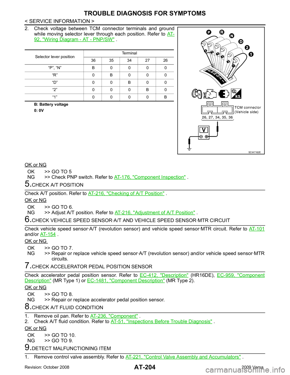
2. Check voltage between TCM connector terminals and ground while moving selector lever through each position. Refer to AT-92, " Wiring Diagram - AT - PNP/SW " .
B: Battery voltage
0: 0V
OK or NG OK >> GO TO 5
NG >> Check PNP switch. Refer to AT-176, " Component Inspection " .
5.
CHECK A/T POSITION
Check A/T position. Refer to AT-216, " Checking of A/T Position " .
OK or NG OK >> GO TO 6.
NG >> Adjust A/T position. Refer to AT-216, " Adjustment of A/T Position " .
6.
CHECK VEHICLE SPEED SENSOR·A/T A ND VEHICLE SPEED SENSOR·MTR CIRCUIT
Check vehicle speed sensor·A/T (revolution senso r) and vehicle speed sensor·MTR circuit. Refer to AT-101and/or
AT-154 .
OK or NG OK >> GO TO 7.
NG >> Repair or replace vehicle speed sensor·A/T (revolution sensor) and/or vehicle speed sensor·MTR
circuits. 7.
CHECK ACCELERATOR PEDAL POSITION SENSOR
Check accelerator pedal position sensor. Refer to EC-412, " Description " (HR16DE),
EC-959, " Component
Description " (MR Type 1) or
EC-1481, " Component Description " (MR Type 2).
OK or NG OK >> GO TO 8.
NG >> Repair or replace accelerator pedal position sensor. 8.
CHECK A/T FLUID CONDITION
1. Remove oil pan. Refer to AT-236, " Component " .
2. Check A/T fluid condition. Refer to AT-51, " Inspections Before Trouble Diagnosis " .
OK or NG OK >> GO TO 10.
NG >> GO TO 9. 9.
DETECT MALFUNCTIONING ITEM
1. Remove control valve assembly. Refer to AT-221, " Control Valve Assembly and Accumulators " .
Selector lever position
Terminal
36 35 34 27 26
“P”, “N” B 0 0 0 0 “R” 0 B 0 0 0
“D” 0 0 B 0 0 “2” 0 0 0 B 0
“1” 0 0 0 0 B SCIA7162E
Page 842 of 4331
![NISSAN LATIO 2009 Service Repair Manual BRC-2< SERVICE INFORMATION >
[ABS]
PRECAUTIONS
SERVICE INFORMATION
PRECAUTIONS
Precaution for Supplemental Restraint Syst em (SRS) "AIR BAG" and "SEAT BELT
PRE-TENSIONER" INFOID:0000000004784402
The NISSAN LATIO 2009 Service Repair Manual BRC-2< SERVICE INFORMATION >
[ABS]
PRECAUTIONS
SERVICE INFORMATION
PRECAUTIONS
Precaution for Supplemental Restraint Syst em (SRS) "AIR BAG" and "SEAT BELT
PRE-TENSIONER" INFOID:0000000004784402
The](/img/5/57359/w960_57359-841.png)
BRC-2< SERVICE INFORMATION >
[ABS]
PRECAUTIONS
SERVICE INFORMATION
PRECAUTIONS
Precaution for Supplemental Restraint Syst em (SRS) "AIR BAG" and "SEAT BELT
PRE-TENSIONER" INFOID:0000000004784402
The Supplemental Restraint System such as “A IR BAG” and “SEAT BELT PRE-TENSIONER”, used along
with a front seat belt, helps to reduce the risk or severi ty of injury to the driver and front passenger for certain
types of collision. This system includes seat belt switch inputs and dual stage front air bag modules. The SRS
system uses the seat belt switches to determine the front air bag deployment, and may only deploy one front
air bag, depending on the severity of a collision and w hether the front occupants are belted or unbelted.
Information necessary to service the system safely is included in the SRS and SB section of this Service Man-
ual.
WARNING:
• To avoid rendering the SRS inopera tive, which could increase the risk of personal injury or death in
the event of a collision which would result in air bag inflation, all maintenance must be performed by
an authorized NISS AN/INFINITI dealer.
• Improper maintenance, including incorrect removal and installation of the SRS can lead to personal
injury caused by unintent ional activation of the system. For re moval of Spiral Cable and Air Bag
Module, see the SRS section.
• Do not use electrical test equipmen t on any circuit related to the SRS unless instructed to in this
Service Manual. SRS wiring harn esses can be identified by yellow and/or orange harnesses or har-
ness connectors.
PRECAUTIONS WHEN USING POWER TOOLS (AIR OR ELECTRIC) AND HAMMERS
WARNING:
• When working near the Airbag Diagnosis Sensor Unit or other Airbag System sensors with the Igni-
tion ON or engine running, DO NOT use air or electri c power tools or strike near the sensor(s) with a
hammer. Heavy vibration could activate the sensor( s) and deploy the air bag(s), possibly causing
serious injury.
• When using air or electric power tools or hammers , always switch the Ignition OFF, disconnect the
battery, and wait at least 3 minu tes before performing any service.
Precaution for Brake System INFOID:0000000004307251
CAUTION:
• Refer to MA-14 for recommended brake fluid.
• Never reuse drained brake fluid.
• Be careful not to splash brake fluid on painted areas; it may cause paint damage. If brake fluid is
splashed on painted areas, wash it away with water immediately.
• To clean or wash all parts of master cylin der and disc brake caliper, use clean brake fluid.
• Never use mineral oils such as gasoline or kerosene. They will ruin rubber parts of the hydraulic sys-
tem.
• Use flare nut wrench when re moving and installing brake
tube.
• If a brake fluid leak is found, the part must be disassembled
without fail. Then it has to be replaced with a new one if a
defect exists.
• Turn the ignition switch OFF an d remove the connector of the
ABS actuator and electric unit (c ontrol unit) or the battery ter-
minal before performing the work.
• Always torque brake lines when installing.
• Burnish the brake contact surf aces after refinishing or replac-
ing rotors, after replacing pads, or if a soft pedal occurs at
very low mileage. Refer to BR-32, " Brake Burnishing Proce-
dure " .
WARNING:
• Clean brake pads and shoes with a waste cloth, then wipe with a dust collector. SBR686C