fuel pump NISSAN LATIO 2010 Service Repair Manual
[x] Cancel search | Manufacturer: NISSAN, Model Year: 2010, Model line: LATIO, Model: NISSAN LATIO 2010Pages: 3745, PDF Size: 73.67 MB
Page 1214 of 3745

DI-4
< SERVICE INFORMATION >
COMBINATION METERS
COMBINATION METERS
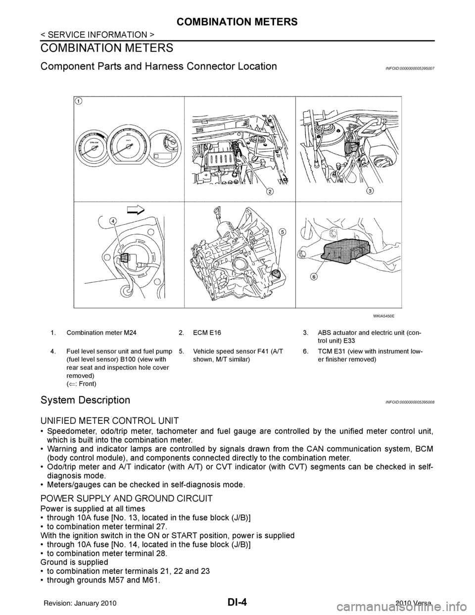
Component Parts and Harness Connector LocationINFOID:0000000005395007
System DescriptionINFOID:0000000005395008
UNIFIED METER CONTROL UNIT
• Speedometer, odo/trip meter, tachometer and fuel gauge are controlled by the unified meter control unit,
which is built into the combination meter.
• Warning and indicator lamps are controlled by signals drawn from the CAN communication system, BCM
(body control module), and components connected directly to the combination meter.
• Odo/trip meter and A/T indicator (with A/T) or CVT i ndicator (with CVT) segments can be checked in self-
diagnosis mode.
• Meters/gauges can be checked in self-diagnosis mode.
POWER SUPPLY AND GROUND CIRCUIT
Power is supplied at all times
• through 10A fuse [No. 13, located in the fuse block (J/B)]
• to combination meter terminal 27.
With the ignition switch in the ON or START position, power is supplied
• through 10A fuse [No. 14, located in the fuse block (J/B)]
• to combination meter terminal 28.
Ground is supplied
• to combination meter terminals 21, 22 and 23
• through grounds M57 and M61.
1. Combination meter M24 2. ECM E16 3. ABS actuator and electric unit (con-
trol unit) E33
4. Fuel level sensor unit and fuel pump (fuel level sensor) B100 (view with
rear seat and inspection hole cover
removed)
(⇐: Front) 5. Vehicle speed sensor F41 (A/T
shown, M/T similar) 6. TCM E31 (view with
instrument low-
er finisher removed)
WKIA5450E
Revision: January 20102010 Versa
Page 1215 of 3745

COMBINATION METERSDI-5
< SERVICE INFORMATION >
C
DE
F
G H
I
J
L
M A
B
DI
N
O P
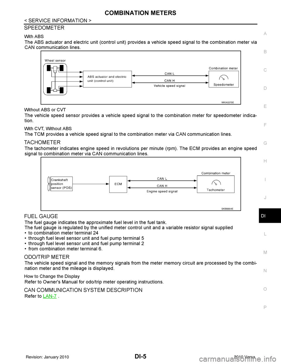
SPEEDOMETER
With ABS
The ABS actuator and electric unit (control unit) provi des a vehicle speed signal to the combination meter via
CAN communication lines.
Without ABS or CVT
The vehicle speed sensor provides a vehicle speed signal to the combination meter for speedometer indica-
tion.
With CVT, Without ABS
The TCM provides a vehicle speed signal to the combination meter via CAN communication lines.
TACHOMETER
The tachometer indicates engine speed in revolutions per minute (rpm). The ECM provides an engine speed
signal to combination meter via CAN communication lines.
FUEL GAUGE
The fuel gauge indicates the approximate fuel level in the fuel tank.
The fuel gauge is regulated by the unified meter control unit and a variable resistor signal supplied
• to combination meter terminal 24
• through fuel level sensor unit and fuel pump terminal 5
• through fuel level sensor unit and fuel pump terminal 2
• from combination meter terminal 6.
ODO/TRIP METER
The vehicle speed signal and the memory signals from the meter memory circuit are processed by the combi-
nation meter and the mileage is displayed.
How to Change the Display
Refer to Owner's Manual for odo/trip meter operating instructions.
CAN COMMUNICATION SYSTEM DESCRIPTION
Refer to LAN-7 .
WKIA5370E
SKIB6904E
Revision: January 20102010 Versa
Page 1228 of 3745

DI-18
< SERVICE INFORMATION >
COMBINATION METERS
OK or NG
OK >> GO TO 2.
NG >> Replace combination meter. Refer to IP-12, "
Removal and Installation" .
2.CHECK HARNESS CONNECTOR
1. Turn ignition switch OFF.
2. Check combination meter and fuel level sensor uni t terminals (meter-side and harness-side) for poor con-
nection.
OK or NG
OK >> GO TO 3.
NG >> Repair or replace terminals or connectors.
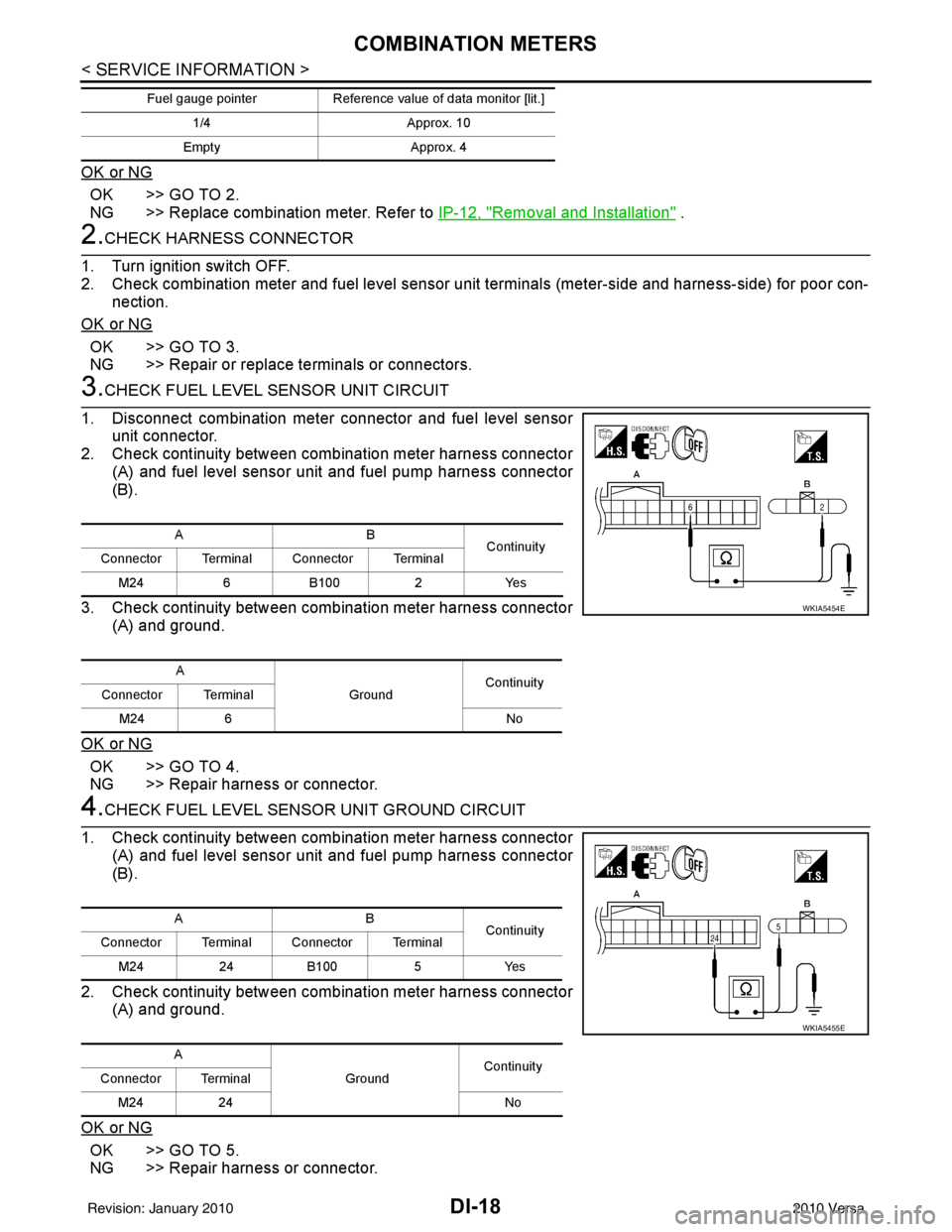
3.CHECK FUEL LEVEL SENSOR UNIT CIRCUIT
1. Disconnect combination meter connector and fuel level sensor unit connector.
2. Check continuity between combination meter harness connector
(A) and fuel level sensor uni t and fuel pump harness connector
(B).
3. Check continuity between combination meter harness connector (A) and ground.
OK or NG
OK >> GO TO 4.
NG >> Repair harness or connector.
4.CHECK FUEL LEVEL SENSOR UNIT GROUND CIRCUIT
1. Check continuity between combination meter harness connector (A) and fuel level sensor uni t and fuel pump harness connector
(B).
2. Check continuity between combination meter harness connector (A) and ground.
OK or NG
OK >> GO TO 5.
NG >> Repair harness or connector.
1/4 Approx. 10
Empty Approx. 4
Fuel gauge pointer
Reference value of data monitor [lit.]
AB
Continuity
Connector Terminal Connector Terminal
M24 6 B100 2Yes
A GroundContinuity
Connector Terminal
M24 6 No
WKIA5454E
AB
Continuity
Connector Terminal Connector Terminal
M24 24 B100 5 Yes
A GroundContinuity
Connector Terminal
M24 24 No
WKIA5455E
Revision: January 20102010 Versa
Page 1230 of 3745

DI-20
< SERVICE INFORMATION >
COMBINATION METERS
Electrical Component Inspection
INFOID:0000000005395025
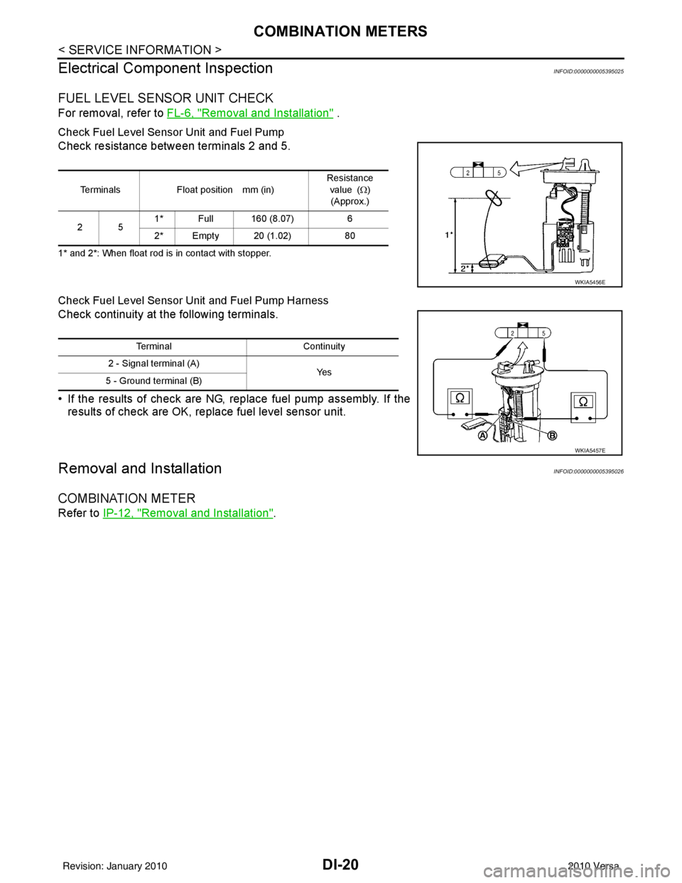
FUEL LEVEL SENSOR UNIT CHECK
For removal, refer to FL-6, "Removal and Installation" .
Check Fuel Level Sensor Unit and Fuel Pump
Check resistance between terminals 2 and 5.
1* and 2*: When float rod is in contact with stopper.
Check Fuel Level Sensor Unit and Fuel Pump Harness
Check continuity at the following terminals.
• If the results of check are NG, replace fuel pump assembly. If the
results of check are OK, replace fuel level sensor unit.
Removal and InstallationINFOID:0000000005395026
COMBINATION METER
Refer to IP-12, "Removal and Installation".
Terminals Float position mm (in) Resistance
value ( Ω)
(Approx.)
25 1* Full 160 (8.07)
6
2* Empty 20 (1.02) 80
WKIA5456E
TerminalContinuity
2 - Signal terminal (A) Ye s
5 - Ground terminal (B)
WKIA5457E
Revision: January 20102010 Versa
Page 1271 of 3745

EC-6
Wiring Diagram ......................................................402
Diagnosis Procedure .............................................402
Component Inspection ...........................................404
Special Repair Requirement ..................................404
P2138 APP SENSOR ..................................... .405
Description ........................................................... ..405
DTC Logic ..............................................................405
Wiring Diagram ......................................................406
Diagnosis Procedure .............................................406
Component Inspection ...........................................409
Special Repair Requirement ..................................409
P2A00 A/F SENSOR 1 ................................... .410
Description ........................................................... ..410
DTC Logic ..............................................................410
Wiring Diagram ......................................................411
Diagnosis Procedure .............................................412
COOLING FAN ................................................415
Description ........................................................... ..415
Component Function Check ..................................415
Wiring Diagram ......................................................416
Diagnosis Procedure .............................................417
Component Inspection ...........................................419
ELECTRICAL LOAD SIGNAL .........................421
Description ........................................................... ..421
Component Function Check ..................................421
Diagnosis Procedure .............................................421
FUEL INJECTOR .............................................423
Description ........................................................... ..423
Component Function Check ..................................423
Wiring Diagram ......................................................424
Diagnosis Procedure .............................................424
Component Inspection ...........................................425
FUEL PUMP .....................................................427
Description ........................................................... ..427
Component Function Check ..................................427
Wiring Diagram ......................................................428
Diagnosis Procedure .............................................428
Component Inspection ...........................................430
IGNITION SIGNAL ...........................................432
Description ........................................................... ..432
Component Function Check ..................................432
Wiring Diagram ......................................................433
Diagnosis Procedure .............................................434
Component Inspection (Ignition Coil with Power
Transistor) .............................................................
437
Component Inspection (Condenser-2) ..................438
MALFUNCTION INDICATOR LAMP ...............439
Description ........................................................... ..439
Component Function Check ..................................439
Wiring Diagram ......................................................440
Diagnosis Procedure .............................................441
ON BOARD REFUELING VAPOR RECOV-
ERY (ORVR) .....................................................
443
Description ........................................................... .443
Component Function Check .................................443
Diagnosis Procedure .............................................443
Component Inspection (Refueling EVAP vapor cut
valve) ................................................................... .
446
Component Inspection (Drain filter) ......................448
POSITIVE CRANKCASE VENTILATION .........449
Description ........................................................... .449
Component Inspection ..........................................449
REFRIGERANT PRESSURE SENSOR ...........450
Description ........................................................... .450
Component Function Check .................................450
Wiring Diagram .....................................................451
Diagnosis Procedure .............................................451
ECU DIAGNOSIS ......................................454
ECM ................................................................ ..454
Reference Value .................................................. .454
Wiring Diagram — ENGINE CONTROL SYSTEM
— ..........................................................................
464
Fail Safe ...............................................................465
DTC Inspection Priority Chart .............................467
DTC Index ............................................................468
How to Set SRT Code .......................................471
How to Erase Permanent DTC .............................473
Test Value and Test Limit .....................................477
SYMPTOM DIAGNOSIS ...........................484
ENGINE CONTROL SYSTEM SYMPTOMS .. ..484
Symptom Table .................................................... .484
NORMAL OPERATING CONDITION ...............488
Description ........................................................... .488
PRECAUTION ...........................................489
PRECAUTIONS .............................................. ..489
Precaution for Supplemental Restraint System
(SRS) "AIR BAG" and "SEAT BELT PRE-TEN-
SIONER" .............................................................. .
489
Precaution Necessary for Steering Wheel Rota-
tion After Battery Disconnect ................................
489
Precaution for Procedure without Cowl Top Cover .490
On Board Diagnosis (OBD) System of Engine and
A/T ........................................................................
490
General Precautions .............................................490
PREPARATION .........................................494
PREPARATION .............................................. ..494
Special Service Tools .......................................... .494
Commercial Service Tools ....................................494
ON-VEHICLE MAINTENANCE .................496
Revision: January 20102010 Versa
Page 1279 of 3745

EC-14
Wiring Diagram ....................................................1010
Diagnosis Procedure ...........................................1011
Component Inspection .........................................1013
Removal and Installation .....................................1013
FUEL PUMP ....................................................1014
Description ...........................................................1014
CONSULT-III Reference Value in Data Monitor
Mode ....................................................................
1014
Wiring Diagram ....................................................1015
Diagnosis Procedure ...........................................1016
Component Inspection .........................................1018
Removal and Installation .....................................1018
IGNITION SIGNAL ..........................................1019
Component Description .......................................1019
Wiring Diagram ....................................................1020
Diagnosis Procedure ...........................................1023
Component Inspection .........................................1026
Removal and Installation .....................................1027
REFRIGERANT PRESSURE SENSOR .........1028
Component Description .......................................1028
Wiring Diagram ....................................................1029
Diagnosis Procedure ............................................1030
Removal and Installation ......................................1032
MIL AND DATA LINK CONNECTOR .............1033
Wiring Diagram ....................................................1033
SERVICE DATA AND SPECIFICATIONS
(SDS) ..............................................................
1035
Fuel Pressure .......................................................1035
Idle Speed and Ignition Timing ............................1035
Calculated Load Value .........................................1035
Mass Air Flow Sensor ..........................................1035
Intake Air Temperature Se nsor ............................1035
Engine Coolant Temperature Sensor ..................1035
Air Fuel Ratio (A/F) Sensor 1 Heater ...................1036
Heated Oxygen sensor 2 Heater .........................1036
Crankshaft Position Sensor (POS) ......................1036
Camshaft Position Sensor (PHASE) ....................1036
Throttle Control Motor ...... ....................................1036
Fuel Injector .........................................................1036
Fuel Pump ............................................................1036
Revision: January 20102010 Versa
Page 1297 of 3745
![NISSAN LATIO 2010 Service Repair Manual EC-32
< FUNCTION DIAGNOSIS >[HR16DE]
ENGINE CONTROL SYSTEM
1. ECM harness connectors
2. ECM 3. IPDM E/R
4. Fuel pump fuse (15A) 5. Intake valve timing control solenoid
valve 6. Knock sensor
7. Refrig NISSAN LATIO 2010 Service Repair Manual EC-32
< FUNCTION DIAGNOSIS >[HR16DE]
ENGINE CONTROL SYSTEM
1. ECM harness connectors
2. ECM 3. IPDM E/R
4. Fuel pump fuse (15A) 5. Intake valve timing control solenoid
valve 6. Knock sensor
7. Refrig](/img/5/57358/w960_57358-1296.png)
EC-32
< FUNCTION DIAGNOSIS >[HR16DE]
ENGINE CONTROL SYSTEM
1. ECM harness connectors
2. ECM 3. IPDM E/R
4. Fuel pump fuse (15A) 5. Intake valve timing control solenoid
valve 6. Knock sensor
7. Refrigerant pressure sensor 8. PCV valve Vehicle front
PBIB2941E
Revision: January 20102010 Versa
Page 1299 of 3745
![NISSAN LATIO 2010 Service Repair Manual EC-34
< FUNCTION DIAGNOSIS >[HR16DE]
ENGINE CONTROL SYSTEM
Component Description
INFOID:0000000005398251
1. Cooling fan motor harness connec- tor 2. Crankshaft position sensor
3. Stop lamp switch
4. B NISSAN LATIO 2010 Service Repair Manual EC-34
< FUNCTION DIAGNOSIS >[HR16DE]
ENGINE CONTROL SYSTEM
Component Description
INFOID:0000000005398251
1. Cooling fan motor harness connec- tor 2. Crankshaft position sensor
3. Stop lamp switch
4. B](/img/5/57358/w960_57358-1298.png)
EC-34
< FUNCTION DIAGNOSIS >[HR16DE]
ENGINE CONTROL SYSTEM
Component Description
INFOID:0000000005398251
1. Cooling fan motor harness connec- tor 2. Crankshaft position sensor
3. Stop lamp switch
4. Brake pedal 5. Accelerator pedal position sensor
harness connector 6. Accelerator pedal position sensor
7. Accelerator pedal 8. Fuel level sensor unit and fuel pump
harness connector (view with in-
spection hole cover removed) 9. Fuel pressure regulator
10. Fuel pump
AWBIA0044ZZ
Component Reference
A/F sensor 1 EC-176, "
Description"
A/F sensor 1 heaterEC-130, "Description"
Accelerator pedal position sensorEC-392, "Description"
Camshaft position sensor (PHASE)EC-262, "Description"
Revision: January 20102010 Versa
Page 1300 of 3745
![NISSAN LATIO 2010 Service Repair Manual ENGINE CONTROL SYSTEMEC-35
< FUNCTION DIAGNOSIS > [HR16DE]
C
D
E
F
G H
I
J
K L
M A
EC
NP
O
Crankshaft position sensor (POS)
EC-257, "Description"
Cooling fan motorEC-60, "System Description"
Electric NISSAN LATIO 2010 Service Repair Manual ENGINE CONTROL SYSTEMEC-35
< FUNCTION DIAGNOSIS > [HR16DE]
C
D
E
F
G H
I
J
K L
M A
EC
NP
O
Crankshaft position sensor (POS)
EC-257, "Description"
Cooling fan motorEC-60, "System Description"
Electric](/img/5/57358/w960_57358-1299.png)
ENGINE CONTROL SYSTEMEC-35
< FUNCTION DIAGNOSIS > [HR16DE]
C
D
E
F
G H
I
J
K L
M A
EC
NP
O
Crankshaft position sensor (POS)
EC-257, "Description"
Cooling fan motorEC-60, "System Description"
Electric throttle control actuatorEC-390, "Description"
Engine coolant temperature sensorEC-161, "Description"
EVAP canister purge volume control solenoid valveEC-285, "Description"
EVAP canister vent control valveEC-295, "Description"
EVAP control system pressure sensorEC-306, "Description"
Fuel injectorEC-423, "Description"
Fuel level sensorEC-336, "Description"
Fuel pumpEC-427, "Description"
Fuel tank temperature sensorEC-234, "Description"
Heated oxygen sensor 2EC-198, "Description"
Heated oxygen sensor 2 heaterEC-134, "Description"
Ignition signalEC-432, "Description"
Intake air temperature sensorEC-156, "Description"
Intake valve timing control solenoid valveEC-78, "System Description"
Knock sensorEC-253, "Description"
Mass air flow sensorEC-142, "Description"
PCV valveEC-449, "Description"
Refrigerant pressure sensorEC-450, "Description"
Stop lamp switchEC-373, "Description"
Throttle control motorEC-386, "Description"
Throttle control motor relayEC-377, "Description"
Throttle position sensorEC-165, "Description"
Component Reference
Revision: January 20102010 Versa
Page 1306 of 3745
![NISSAN LATIO 2010 Service Repair Manual MULTIPORT FUEL INJECTION SYSTEMEC-41
< FUNCTION DIAGNOSIS > [HR16DE]
C
D
E
F
G H
I
J
K L
M A
EC
NP
O
1. ECM harness connectors
2. ECM3. IPDM E/R
4. Fuel pump fuse (15A) 5. Intake valve timing control NISSAN LATIO 2010 Service Repair Manual MULTIPORT FUEL INJECTION SYSTEMEC-41
< FUNCTION DIAGNOSIS > [HR16DE]
C
D
E
F
G H
I
J
K L
M A
EC
NP
O
1. ECM harness connectors
2. ECM3. IPDM E/R
4. Fuel pump fuse (15A) 5. Intake valve timing control](/img/5/57358/w960_57358-1305.png)
MULTIPORT FUEL INJECTION SYSTEMEC-41
< FUNCTION DIAGNOSIS > [HR16DE]
C
D
E
F
G H
I
J
K L
M A
EC
NP
O
1. ECM harness connectors
2. ECM3. IPDM E/R
4. Fuel pump fuse (15A) 5. Intake valve timing control solenoid
valve 6. Knock sensor
7. Refrigerant pressure sensor 8. PCV valve Vehicle front
PBIB2941E
Revision: January 20102010 Versa