air filter NISSAN LATIO 2011 Service User Guide
[x] Cancel search | Manufacturer: NISSAN, Model Year: 2011, Model line: LATIO, Model: NISSAN LATIO 2011Pages: 3787, PDF Size: 78.35 MB
Page 212 of 3787
TROUBLE DIAGNOSIS FOR SYMPTOMSAT-195
< SERVICE INFORMATION >
DE
F
G H
I
J
K L
M A
B
AT
N
O P
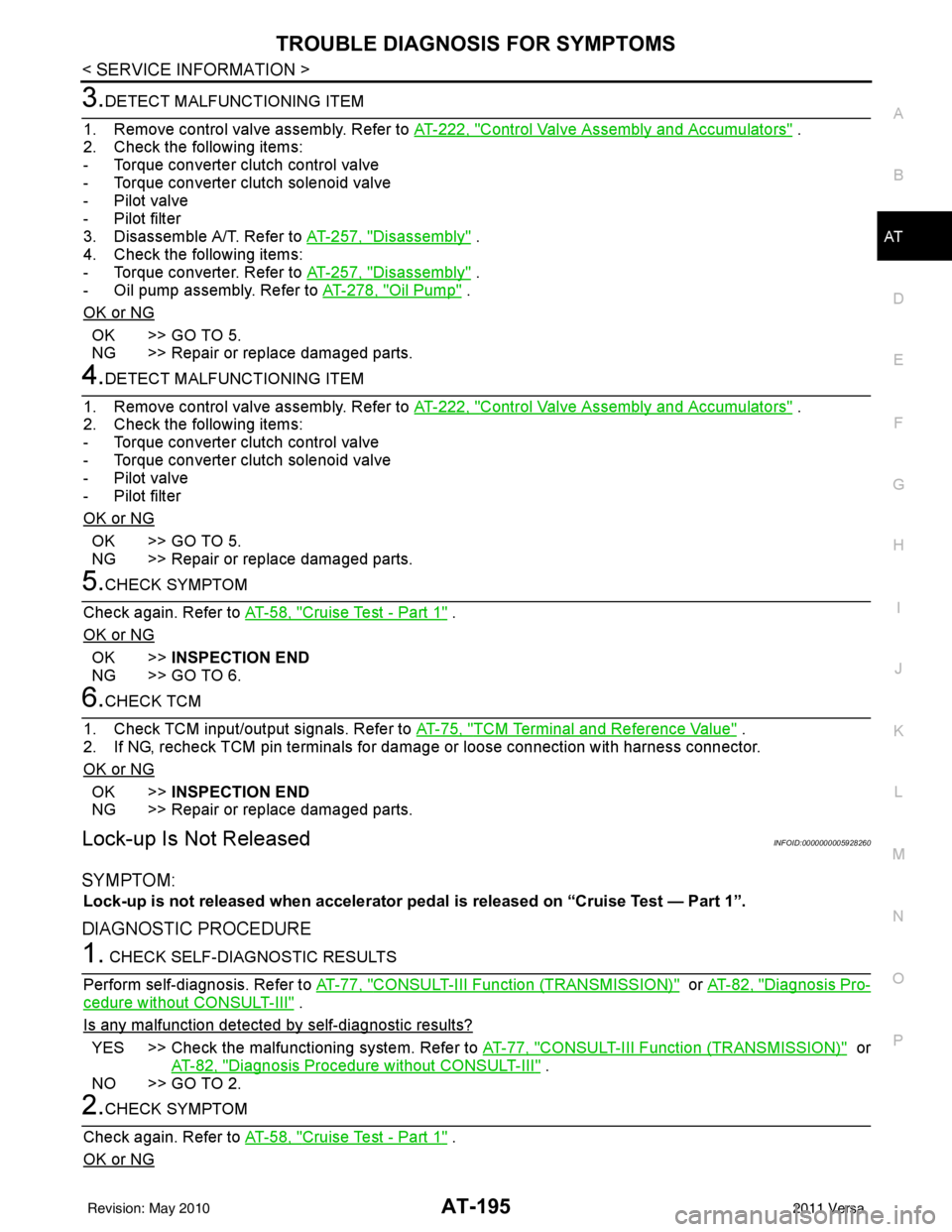
3.DETECT MALFUNCTIONING ITEM
1. Remove control valve assembly. Refer to AT-222, "
Control Valve Assembly and Accumulators" .
2. Check the following items:
- Torque converter clutch control valve
- Torque converter clutch solenoid valve
- Pilot valve
- Pilot filter
3. Disassemble A/T. Refer to AT-257, "
Disassembly" .
4. Check the following items:
- Torque converter. Refer to AT-257, "
Disassembly" .
- Oil pump assembly. Refer to AT-278, "
Oil Pump" .
OK or NG
OK >> GO TO 5.
NG >> Repair or replace damaged parts.
4.DETECT MALFUNCTIONING ITEM
1. Remove control valve assembly. Refer to AT-222, "
Control Valve Assembly and Accumulators" .
2. Check the following items:
- Torque converter clutch control valve
- Torque converter clutch solenoid valve
- Pilot valve
- Pilot filter
OK or NG
OK >> GO TO 5.
NG >> Repair or replace damaged parts.
5.CHECK SYMPTOM
Check again. Refer to AT-58, "
Cruise Test - Part 1" .
OK or NG
OK >> INSPECTION END
NG >> GO TO 6.
6.CHECK TCM
1. Check TCM input/output signals. Refer to AT-75, "
TCM Terminal and Reference Value" .
2. If NG, recheck TCM pin terminals for dam age or loose connection with harness connector.
OK or NG
OK >> INSPECTION END
NG >> Repair or replace damaged parts.
Lock-up Is Not ReleasedINFOID:0000000005928260
SYMPTOM:
Lock-up is not released when accelerator peda l is released on “Cruise Test — Part 1”.
DIAGNOSTIC PROCEDURE
1. CHECK SELF-DIAGNOSTIC RESULTS
Perform self-diagnosis. Refer to AT-77, "
CONSULT-III Function (TRANSMISSION)" or AT-82, "Diagnosis Pro-
cedure without CONSULT-III" .
Is any malfunction detected by self-diagnostic results?
YES >> Check the malfuncti oning system. Refer to AT-77, "CONSULT-III Function (TRANSMISSION)" or
AT-82, "
Diagnosis Procedure without CONSULT-III" .
NO >> GO TO 2.
2.CHECK SYMPTOM
Check again. Refer to AT-58, "
Cruise Test - Part 1" .
OK or NG
Revision: May 2010 2011 Versa
Page 299 of 3787
AT-282
< SERVICE INFORMATION >
REPAIR FOR COMPONENT PARTS
DISASSEMBLY
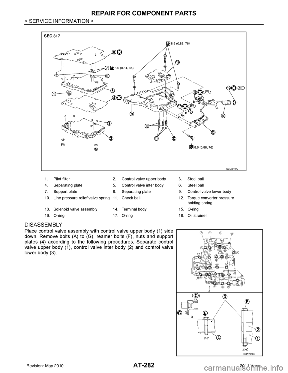
Place control valve assembly with control valve upper body (1) side
down. Remove bolts (A) to (G), reamer bolts (F), nuts and support
plates (4) according to the following procedures. Separate control
valve upper body (1), control valve inter body (2) and control valve
lower body (3).
1. Pilot filter2. Control valve upper body 3. Steel ball
4. Separating plate 5. Control valve inter body 6. Steel ball
7. Support plate 8. Separating plate9. Control valve lower body
10. Line pressure relief valve spring 11. Check ball 12. Torque converter pressure
holding spring
13. Solenoid valve assembly 14. Terminal body 15. O-ring
16. O-ring 17. O-ring18. Oil strainer
SCIA8407J
SCIA7058E
Revision: May 2010 2011 Versa
Page 301 of 3787
AT-284
< SERVICE INFORMATION >
REPAIR FOR COMPONENT PARTS
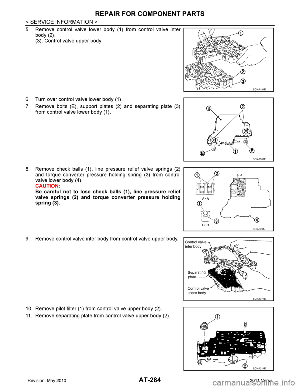
5. Remove control valve lower body (1) from control valve interbody (2).
(3): Control valve upper body
6. Turn over control valve lower body (1).
7. Remove bolts (E), support plates (2) and separating plate (3) from control valve lower body (1).
8. Remove check balls (1), line pressure relief valve springs (2) and torque converter pressure holding spring (3) from control
valve lower body (4).
CAUTION:
Be careful not to lose check ba lls (1), line pressure relief
valve springs (2) and torque converter pressure holding
spring (3).
9. Remove control valve inter body from control valve upper body.
10. Remove pilot filter (1) from control valve upper body (2).
11. Remove separating plate from control valve upper body (2).
SCIA7181E
SCIA7009E
SCIA6491J
SCIA4977E
SCIA7011E
Revision: May 2010 2011 Versa
Page 304 of 3787
REPAIR FOR COMPONENT PARTSAT-287
< SERVICE INFORMATION >
DE
F
G H
I
J
K L
M A
B
AT
N
O P
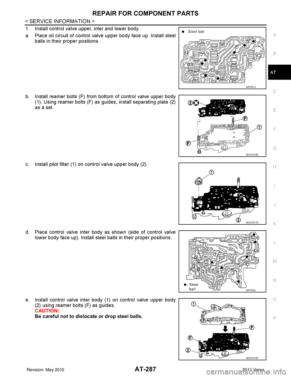
1. Install control valve upper, inter and lower body.
a. Place oil circuit of control valve upper body face up. Install steel balls in their proper positions.
b. Install reamer bolts (F) from bottom of control valve upper body (1). Using reamer bolts (F) as guides, install separating plate (2)
as a set.
c. Install pilot filter (1) on control valve upper body (2).
d. Place control valve inter body as shown (side of control valve lower body face up). Install steel balls in their proper positions.
e. Install control valve inter body (1) on control valve upper body (2) using reamer bolts (F) as guides.
CAUTION:
Be careful not to dislocate or drop steel balls.
SAT871J
SCIA7010E
SCIA7011E
SAT870J
SCIA7012E
Revision: May 2010 2011 Versa
Page 863 of 3787
BR-16
< SERVICE INFORMATION >
BRAKE MASTER CYLINDER
INSTALLATION
CAUTION:
• Refill using recommended brake fluid. Refer to MA-14, "
Fluids and Lubricants".
• Never reuse drained brake fluid.
• Check if the rod of primary piston has dust or scratches.
1. Install master cylinder to brake booster assembly, and tighten nuts to the specified torque.
CAUTION:
• Do not damage or strain rod of primary piston.
• Apply silicone grease for O-ring, primary piston rod andto inside of booster.
2. Install brake tube to master cylinder, and temporarily tighten the flare nuts on the brake tube to master cyl- inder by hand.
3. Install brake tube to brake hose, then tighten flare nut to the specified torque using a flare nut torque
wrench. Refer to BR-11, "
Hydraulic Circuit".
4. Connect the clutch hose to the reservoir tank, if equipped.
5. Connect brake fluid level switch harness connector.
6. Install the air cleaner. Refer to EM-135, "
Removal and Installation".
7. Install the air duct. Refer to EM-135, "
Removal and Installation".
8. Install the battery. Refer to SC-7, "
Removal and Installation".
9. Refill with new brake fluid and bleed the air from the brake hydraulic system. Refer toBR-9, "
Bleeding
Brake System".
Disassembly and AssemblyINFOID:0000000005928404
COMPONENTS
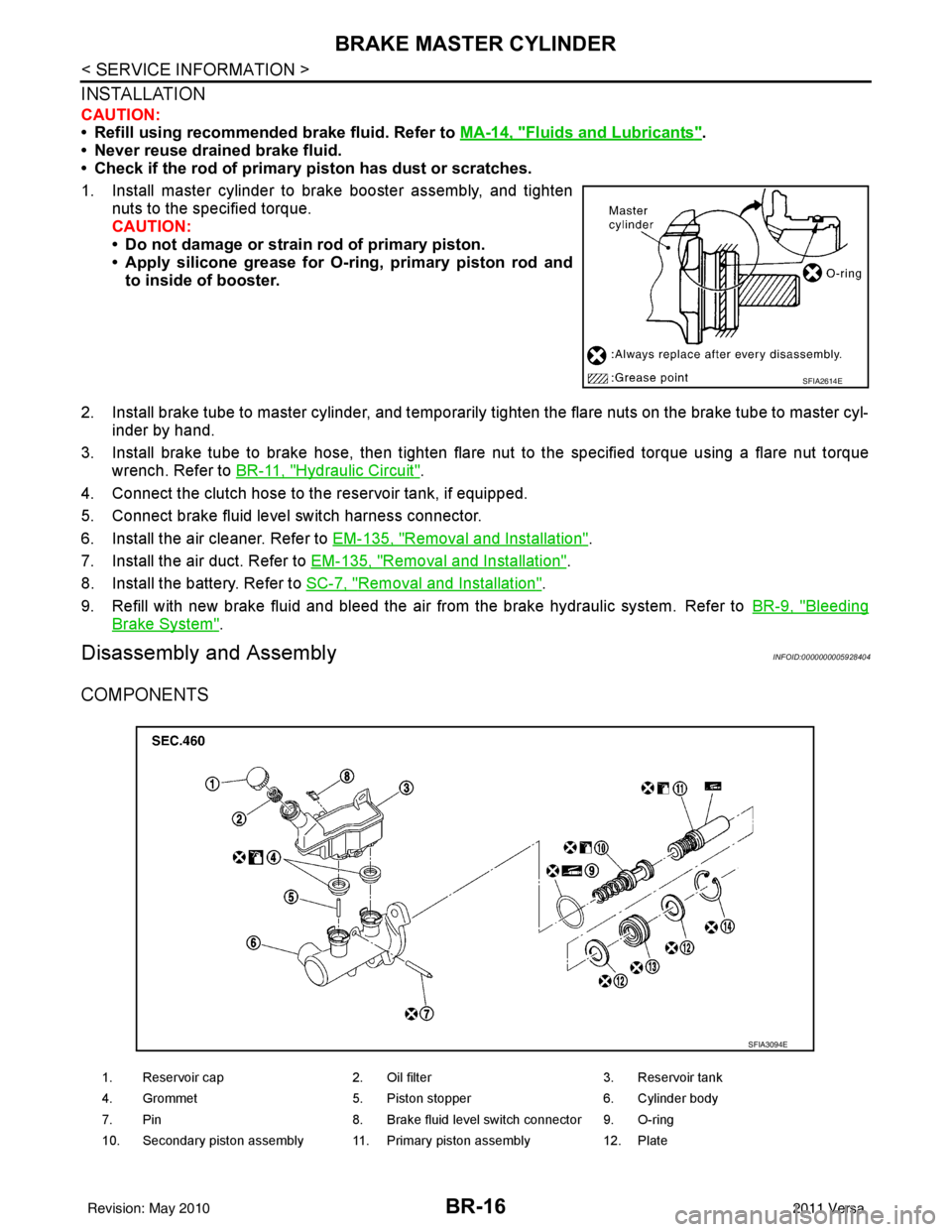
SFIA2614E
1. Reservoir cap2. Oil filter 3. Reservoir tank
4. Grommet 5. Piston stopper 6. Cylinder body
7. Pin 8. Brake fluid level switch connector 9. O-ring
10. Secondary piston assembly 11. Primary piston assembly 12. Plate
SFIA3094E
Revision: May 2010 2011 Versa
Page 1072 of 3787
![NISSAN LATIO 2011 Service User Guide CVT FLUIDCVT-17
< SERVICE INFORMATION > [RE0F08B]
D
E
F
G H
I
J
K L
M A
B
CVT
N
O P
3. Insert the extension adapter hose of a can of Transmission Cooler Cleaner (Nissan P/N 999MP-AM006) into the coole](/img/5/57357/w960_57357-1071.png "NISSAN LATIO 2011 Service User Guide CVT FLUIDCVT-17
< SERVICE INFORMATION > [RE0F08B]
D
E
F
G H
I
J
K L
M A
B
CVT
N
O P
3. Insert the extension adapter hose of a can of Transmission Cooler Cleaner (Nissan P/N 999MP-AM006) into the coole")
CVT FLUIDCVT-17
< SERVICE INFORMATION > [RE0F08B]
D
E
F
G H
I
J
K L
M A
B
CVT
N
O P
3. Insert the extension adapter hose of a can of Transmission Cooler Cleaner (Nissan P/N 999MP-AM006) into the cooler out-
let hose.
CAUTION:
• Wear safety glasses and rubber gloves when spraying theTransmission Cooler Cleaner.
• Spray Transmission Cooler Cleaner only with adequate
ventilation.
• Avoid contact with eyes and skin.
• Do not breath vapors or spray mist.
4. Hold the hose and can as high as possible and spray Transmis- sion Cooler Cleaner in a continuous stream into the cooler outlet
hose until CVT fluid flows out of t he cooler inlet hose for 5 seconds.
5. Tie a common white, basket-type coffee filter to the end of the cooler inlet hose.
6. Insert the tip of an air gun into the end of the cooler outlet hose.
7. Wrap a shop rag around the air gun tip and end of cooler outlet hose.
8. Blow compressed air regulated to 490 to 883 kPa (5 to 9 kg/cm
2,
71 to 128 psi) through the cooler outlet hose to force any
remaining CVT fluid into the coffee filter.
9. Remove the coffee filter from the end of the cooler inlet hose.
10. Perform "CVT FLUID COOLER INSPECTION PROCEDURE".
CVT FLUID COOLER INSPECTION PROCEDURE
1. Inspect the coffee filter for debris.
a. If small metal debris less than 1 mm (0.040 in) in size or metal powder is found in the coffee filter, this is normal. If normal
debris is found, the CVT fluid cooler/radiator can be re-used and
the procedure is ended.
SCIA4421E
SCIA4424E
SCIA4425E
SCIA2967E
Revision: May 2010 2011 Versa
Page 1298 of 3787

EC-4
DTC Logic ..............................................................249
Wiring Diagram ......................................................250
Diagnosis Procedure .............................................250
Component Inspection ...........................................252
P0222, P0223 TP SENSOR .............................253
Description ........................................................... ..253
DTC Logic ..............................................................253
Wiring Diagram ......................................................254
Diagnosis Procedure .............................................254
Component Inspection ...........................................256
Special Repair Requirement ..................................256
P0300, P0301, P0302, P0303, P0304 MIS-
FIRE ................................................................ .
257
DTC Logic ............................................................ ..257
Diagnosis Procedure .............................................258
P0327, P0328 KS .............................................263
Description ........................................................... ..263
DTC Logic ..............................................................263
Wiring Diagram ......................................................264
Diagnosis Procedure .............................................264
Component Inspection ...........................................265
P0335 CKP SENSOR (POS) ...........................267
Description ........................................................... ..267
DTC Logic ..............................................................267
Wiring Diagram ......................................................268
Diagnosis Procedure .............................................269
Component Inspection ...........................................271
P0340 CMP SENSOR (PHASE) ......................272
Description ........................................................... ..272
DTC Logic ..............................................................272
Wiring Diagram ......................................................274
Diagnosis Procedure .............................................274
Component Inspection ...........................................276
P0420 THREE WAY CATALYST FUNCTION .277
DTC Logic ..............................................................277
Component Function Check ..................................278
Diagnosis Procedure .............................................279
P0441 EVAP CONTROL SYSTEM ..................282
DTC Logic ............................................................ ..282
Component Function Check ..................................283
Diagnosis Procedure .............................................284
Component Inspection (Drain filter) .......................287
P0442 EVAP CONTROL SYSTEM ..................288
DTC Logic ............................................................ ..288
Diagnosis Procedure .............................................289
Component Inspection (Fuel filler cap) ..................293
Component Inspection (Drain filter) .......................293
P0443 EVAP CANISTER PURGE VOLUME
CONTROL SOLENOID VALVE .......................
295
Description ........................................................... ..295
DTC Logic ..............................................................295
Wiring Diagram ......................................................297
Diagnosis Procedure ............................................ .297
Component Inspection ..........................................300
P0444, P0445 EVAP CANISTER PURGE
VOLUME CONTROL SOLENOID VALVE .......
301
Description ........................................................... .301
DTC Logic .............................................................301
Wiring Diagram .....................................................302
Diagnosis Procedure .............................................302
Component Inspection ..........................................304
P0447 EVAP CANISTER VENT CONTROL
VALVE ..............................................................
305
Description ........................................................... .305
DTC Logic .............................................................305
Wiring Diagram .....................................................306
Diagnosis Procedure .............................................306
Component Inspection ..........................................308
P0448 EVAP CANISTER VENT CONTROL
VALVE ..............................................................
310
Description ........................................................... .310
DTC Logic .............................................................310
Wiring Diagram .....................................................312
Diagnosis Procedure .............................................312
Component Inspection ..........................................314
P0451 EVAP CONTROL SYSTEM PRES-
SURE SENSOR ................................................
316
Description ........................................................... .316
DTC Logic .............................................................316
Diagnosis Procedure .............................................316
Component Inspection ..........................................318
P0452 EVAP CONTROL SYSTEM PRES-
SURE SENSOR ................................................
319
Description ........................................................... .319
DTC Logic .............................................................319
Wiring Diagram .....................................................321
Diagnosis Procedure .............................................321
Component Inspection ..........................................324
P0453 EVAP CONTROL SYSTEM PRES-
SURE SENSOR ................................................
326
Description ........................................................... .326
DTC Logic .............................................................326
Wiring Diagram .....................................................328
Diagnosis Procedure .............................................328
Component Inspection ..........................................332
P0455 EVAP CONTROL SYSTEM ..................333
DTC Logic .............................................................333
Diagnosis Procedure .............................................334
Component Inspection (Fuel filler cap) .................337
Component Inspection (Drain filter) ......................338
P0456 EVAP CONTROL SYSTEM ..................339
DTC Logic .............................................................339
Component Function Check .................................341
Diagnosis Procedure .............................................341
Revision: May 2010 2011 Versa
Page 1299 of 3787
EC-5
C
DE
F
G H
I
J
K L
M
EC A
N
O P
Component Inspection (Fuel filler cap) ...............
..
344
Component Inspection (Drain filter) ......................345
P0460 FUEL LEVEL SENSOR ...................... ..346
Description .......................................................... ..346
DTC Logic .............................................................346
Diagnosis Procedure .............................................346
P0461 FUEL LEVEL SENSOR ........................347
Description .......................................................... ..347
DTC Logic .............................................................347
Component Function Check ..................................347
Diagnosis Procedure .............................................348
P0462, P0463 FUEL LEVEL SENSOR ............349
Description .......................................................... ..349
DTC Logic .............................................................349
Diagnosis Procedure .............................................349
P0500 VSS .......................................................351
Description .......................................................... ..351
DTC Logic .............................................................351
Component Function Check ..................................352
Diagnosis Procedure .............................................352
P0506 ISC SYSTEM .........................................353
Description .......................................................... ..353
DTC Logic .............................................................353
Diagnosis Procedure .............................................353
P0507 ISC SYSTEM .........................................355
Description .......................................................... ..355
DTC Logic .............................................................355
Diagnosis Procedure .............................................355
P0603 ECM POWER SUPPLY .........................357
Description .......................................................... ..357
DTC Logic .............................................................357
Diagnosis Procedure .............................................357
P0605 ECM .......................................................359
Description ............................................................359
DTC Logic .............................................................359
Diagnosis Procedure .............................................360
P0607 ECM .......................................................361
Description ............................................................361
DTC Logic .............................................................361
Diagnosis Procedure .............................................361
P0643 SENSOR POWER SUPPLY .................362
DTC Logic ........................................................... ..362
Wiring Diagram .....................................................363
Diagnosis Procedure .............................................363
P0850 PNP SWITCH ........................................366
Description ............................................................366
DTC Logic .............................................................366
Component Function Check ..................................367
Wiring Diagram .....................................................368
Diagnosis Procedure .............................................368
P1148 CLOSED LOOP CONTROL ................371
DTC Logic ............................................................ ..371
P1217 ENGINE OVER TEMPERATURE ........372
DTC Logic ..............................................................372
Component Function Check ..................................372
Diagnosis Procedure .............................................373
P1225 TP SENSOR .........................................376
Description .............................................................376
DTC Logic ..............................................................376
Diagnosis Procedure .............................................376
Special Repair Requirement ..................................377
P1226 TP SENSOR .........................................378
Description .............................................................378
DTC Logic ..............................................................378
Diagnosis Procedure .............................................378
Special Repair Requirement ..................................379
P1421 COLD START CONTROL ...................380
Description .............................................................380
DTC Logic ..............................................................380
Diagnosis Procedure .............................................380
P1715 INPUT SPEED SENSOR (PRIMARY
SPEED SENSOR) ...........................................
382
Description ........................................................... ..382
DTC Logic ..............................................................382
Diagnosis Procedure .............................................382
P1805 BRAKE SWITCH .................................383
Description .............................................................383
DTC Logic ..............................................................383
Wiring Diagram ......................................................384
Diagnosis Procedure .............................................384
Component Inspection (Stop Lamp Switch) ..........386
P2100, P2103 THROTTLE CONTROL MO-
TOR RELAY ....................................................
387
Description .............................................................387
DTC Logic ..............................................................387
Wiring Diagram ......................................................388
Diagnosis Procedure .............................................388
P2101 ELECTRIC THROTTLE CONTROL
FUNCTION ......................................................
391
Description ........................................................... ..391
DTC Logic ..............................................................391
Wiring Diagram ......................................................392
Diagnosis Procedure .............................................392
Component Inspection ...........................................395
Special Repair Requirement ..................................395
P2118 THROTTLE CONTROL MOTOR .........396
Description .............................................................396
DTC Logic ..............................................................396
Wiring Diagram ......................................................397
Diagnosis Procedure .............................................397
Component Inspection ...........................................398
Special Repair Requirement ..................................399
Revision: May 2010 2011 Versa
Page 1300 of 3787

EC-6
P2119 ELECTRIC THROTTLE CONTROL
ACTUATOR .....................................................
400
Description ........................................................... ..400
DTC Logic ..............................................................400
Diagnosis Procedure .............................................400
Special Repair Requirement ..................................401
P2122, P2123 APP SENSOR ......................... .402
Description ........................................................... ..402
DTC Logic ..............................................................402
Wiring Diagram ......................................................403
Diagnosis Procedure .............................................403
Component Inspection ...........................................405
Special Repair Requirement ..................................405
P2127, P2128 APP SENSOR ......................... .406
Description ........................................................... ..406
DTC Logic ..............................................................406
Wiring Diagram ......................................................407
Diagnosis Procedure .............................................407
Component Inspection ...........................................409
Special Repair Requirement ..................................410
P2135 TP SENSOR ........................................ .411
Description ........................................................... ..411
DTC Logic ..............................................................411
Wiring Diagram ......................................................412
Diagnosis Procedure .............................................412
Component Inspection ...........................................414
Special Repair Requirement ..................................414
P2138 APP SENSOR ..................................... .415
Description ........................................................... ..415
DTC Logic ..............................................................415
Wiring Diagram ......................................................416
Diagnosis Procedure .............................................416
Component Inspection ...........................................419
Special Repair Requirement ..................................419
P2A00 A/F SENSOR 1 ................................... .420
Description ........................................................... ..420
DTC Logic ..............................................................420
Wiring Diagram ......................................................421
Diagnosis Procedure .............................................422
COOLING FAN ................................................425
Description ........................................................... ..425
Component Function Check ..................................425
Wiring Diagram ......................................................426
Diagnosis Procedure .............................................427
Component Inspection ...........................................429
ELECTRICAL LOAD SIGNAL .........................431
Description ........................................................... ..431
Component Function Check ..................................431
Diagnosis Procedure .............................................431
FUEL INJECTOR .............................................433
Description ........................................................... ..433
Component Function Check ..................................433
Wiring Diagram ......................................................434
Diagnosis Procedure ............................................ .434
Component Inspection ..........................................435
FUEL PUMP .....................................................437
Description ........................................................... .437
Component Function Check .................................437
Wiring Diagram .....................................................438
Diagnosis Procedure .............................................438
Component Inspection ..........................................440
IGNITION SIGNAL ............................................442
Description ........................................................... .442
Component Function Check .................................442
Wiring Diagram .....................................................443
Diagnosis Procedure .............................................444
Component Inspection (Ignition Coil with Power
Transistor) ............................................................ .
447
Component Inspection (Condenser-2) ..................448
MALFUNCTION INDICATOR LAMP ................449
Description ........................................................... .449
Component Function Check .................................449
Wiring Diagram .....................................................450
Diagnosis Procedure .............................................451
ON BOARD REFUELING VAPOR RECOV-
ERY (ORVR) .....................................................
453
Description ........................................................... .453
Component Function Check .................................453
Diagnosis Procedure .............................................453
Component Inspection (Refueling EVAP vapor cut
valve) ................................................................... .
456
Component Inspection (Drain filter) ......................458
POSITIVE CRANKCASE VENTILATION .........459
Description ........................................................... .459
Component Inspection ..........................................459
REFRIGERANT PRESSURE SENSOR ...........460
Description ........................................................... .460
Component Function Check .................................460
Wiring Diagram .....................................................461
Diagnosis Procedure .............................................461
ECU DIAGNOSIS ......................................464
ECM ................................................................ ..464
Reference Value .................................................. .464
Wiring Diagram — ENGINE CONTROL SYSTEM
— ..........................................................................
474
Fail Safe ...............................................................475
DTC Inspection Priority Chart .............................477
DTC Index ............................................................478
Test Value and Test Limit .....................................481
SYMPTOM DIAGNOSIS ...........................488
ENGINE CONTROL SYSTEM SYMPTOMS .. ..488
Symptom Table .................................................... .488
NORMAL OPERATING CONDITION ...............492
Revision: May 2010 2011 Versa
Page 1411 of 3787
![NISSAN LATIO 2011 Service User Guide TROUBLE DIAGNOSIS - SPECIFICATION VALUEEC-117
< COMPONENT DIAGNOSIS > [HR16DE]
C
D
E
F
G H
I
J
K L
M A
EC
NP
O
NOTE:
Check “A/F ALPHA-B1” for approximately 1 minute because
it may fluctuate. It i](/img/5/57357/w960_57357-1410.png "NISSAN LATIO 2011 Service User Guide TROUBLE DIAGNOSIS - SPECIFICATION VALUEEC-117
< COMPONENT DIAGNOSIS > [HR16DE]
C
D
E
F
G H
I
J
K L
M A
EC
NP
O
NOTE:
Check “A/F ALPHA-B1” for approximately 1 minute because
it may fluctuate. It i")
TROUBLE DIAGNOSIS - SPECIFICATION VALUEEC-117
< COMPONENT DIAGNOSIS > [HR16DE]
C
D
E
F
G H
I
J
K L
M A
EC
NP
O
NOTE:
Check “A/F ALPHA-B1” for approximately 1 minute because
it may fluctuate. It is NG if the indication is
out of the SP value even a little.
Is the measurement value within the SP value?
YES >> GO TO 17.
NO-1 >> Less than the SP value: GO TO 2.
NO-2 >> More than the SP value: GO TO 3.
2.CHECK “B/FUEL SCHDL”
Select “B/FUEL SCHDL” in “SPEC” of “DATA MONITOR” m ode, and make sure that the indication is within the
SP value.
Is the measurement value within the SP value?
YES >> GO TO 4.
NO >> More than the SP value: GO TO 19.
3.CHECK “B/FUEL SCHDL”
Select “B/FUEL SCHDL” in “SPEC” of “DATA MONITOR” m ode, and make sure that the indication is within the
SP value.
Is the measurement value within the SP value?
YES >> GO TO 6.
NO-1 >> More than the SP value: GO TO 6.
NO-2 >> Less than the SP value: GO TO 25.
4.CHECK “A/F ALPHA-B1”
1. Stop the engine.
2. Disconnect PCV hose, and then plug it.
3. Start engine.
4. Select “A/F ALPHA-B1” in “SPEC” of “DATA MONITOR” mode, and make sure that the indication is within
the SP value.
Is the measurement value within the SP value?
YES >> GO TO 5.
NO >> GO TO 6.
5.CHANGE ENGINE OIL
1. Stop the engine.
2. Change engine oil. NOTE:
This symptom may occur when a large amount of gas oline is mixed with engine oil because of driving
conditions (such as when engine oil temperature does not rise enough since a journey distance is too
short during winter). The symptom will not be detect ed after changing engine oil or changing driving con-
dition.
>>INSPECTION END
6.CHECK FUEL PRESSURE
Check fuel pressure. (Refer to EC-499, "
Inspection".)
Is the inspection result normal?
YES >> GO TO 9.
NO-1 >> Fuel pressure is too high: Replace “fuel leve l sensor unit, fuel filter and pump assembly” (refer to
FL-6, "
Removal and Installation") and then GO TO 8.
NO-2 >> Fuel pressure is too low: GO TO 7.
7.DETECT MALFUNCTIONING PART
Check fuel hoses and fuel tubes for clogging
Is the inspection result normal?
YES >> Replace “fuel level sensor unit, f uel filter and pump assembly” (refer to FL-6, "Removal and Instal-
lation") and then GO TO 8.
NO >> Repair or replace and then GO TO 8.
Revision: May 2010 2011 Versa