fuel cap release NISSAN LATIO 2011 Service User Guide
[x] Cancel search | Manufacturer: NISSAN, Model Year: 2011, Model line: LATIO, Model: NISSAN LATIO 2011Pages: 3787, PDF Size: 78.35 MB
Page 2545 of 3787
![NISSAN LATIO 2011 Service User Guide FUEL INJECTOR AND FUEL TUBEEM-155
< SERVICE INFORMATION > [MR18DE]
C
D
E
F
G H
I
J
K L
M A
EM
NP
O
4. Disconnect fuel feed hose from hose clamp.
NOTE:
There is no fuel return path.
5. With the sleeve NISSAN LATIO 2011 Service User Guide FUEL INJECTOR AND FUEL TUBEEM-155
< SERVICE INFORMATION > [MR18DE]
C
D
E
F
G H
I
J
K L
M A
EM
NP
O
4. Disconnect fuel feed hose from hose clamp.
NOTE:
There is no fuel return path.
5. With the sleeve](/img/5/57357/w960_57357-2544.png)
FUEL INJECTOR AND FUEL TUBEEM-155
< SERVICE INFORMATION > [MR18DE]
C
D
E
F
G H
I
J
K L
M A
EM
NP
O
4. Disconnect fuel feed hose from hose clamp.
NOTE:
There is no fuel return path.
5. With the sleeve side of quick connector release facing quick connector, install quick connector release onto fuel tube.
6. Insert quick connector release into quick connector until sleeve contacts and goes no further. Hold quick connector release on
that position.
CAUTION:
Inserting quick connector re lease hard will not disconnect
quick connector. Hold qui ck connector release where it
contacts and goes no further.
7. Draw and pull out quick connector straight from fuel tube. CAUTION:
• Pull quick connector holding (A) position.
• Do not pull with lateral force applied. O-ring inside quick connector may be damaged.
• Prepare container and cloth be forehand as fuel will leak out.
• Avoid fire and sparks.
• Keep parts away from heat source. Especially, be careful when welding is performed around
them.
• Do not expose parts to battery electrolyte or other acids.
• Do not bend or twist connection between quick co nnector and fuel feed hose during installation/
removal.
• To keep clean the connecting portion and to avoid dam-
age and foreign materials, cover them completely with
plastic bags or something similar.
8. Remove intake manifold. Refer to EM-137
.
1 : Quick connector cap
PBIC3771E
KBIA0702E
PBIC2205E
Revision: May 2010 2011 Versa
Page 2588 of 3787
![NISSAN LATIO 2011 Service User Guide EM-198
< SERVICE INFORMATION >[MR18DE]
ENGINE ASSEMBLY
• Use either 2-pole lift type or separate type lift as
best you can. If board-on type is used for unavoid-
able reasons, support at the rear a NISSAN LATIO 2011 Service User Guide EM-198
< SERVICE INFORMATION >[MR18DE]
ENGINE ASSEMBLY
• Use either 2-pole lift type or separate type lift as
best you can. If board-on type is used for unavoid-
able reasons, support at the rear a](/img/5/57357/w960_57357-2587.png)
EM-198
< SERVICE INFORMATION >[MR18DE]
ENGINE ASSEMBLY
• Use either 2-pole lift type or separate type lift as
best you can. If board-on type is used for unavoid-
able reasons, support at the rear axle jacking point with a transmission jack or similar tool before
starting work, in preparation for the backward shift of center of gravity.
• For supporting points for lifting and jacking point at rear axle, refer to GI-38, "
Garage Jack and
Safety Stand and 2-Pole Lift".
REMOVAL
Remove the engine and the transaxle assembly from t he vehicle downward. Separate the engine and the tran-
saxle.
1. Remove engine under cover. Refer to EI-15, "
Removal and Installation".
2. Drain engine coolant from radiator. Refer to CO-36, "
Changing Engine Coolant".
CAUTION:
• Perform this step when the engine is cold.
• Do not spill engine coolant on drive belt.
3. Drain clutch fluid (M/T models). Refer to CL-9, "
Air Bleeding Procedure".
4. Remove front fender protector (RH and LH). Refer to EI-26
.
5. Remove exhaust front tube. Refer to EX-10
.
6. Remove drive shafts (LH and RH) from steering knuckle. Refer to FA X - 9
.
7. Remove transaxle joint bolts which pierce at oil pan (upper) lower rear side. Refer to AT-233
(A/T models),
CVT-180, "
Removal and Installation" (CVT models) or MT-61, "Removal and Installation" (M/T models).
8. Remove rear torque rod (1). NOTE:
A/T model shown CVT and M/T models similar.
9. Remove hood assembly. Refer to BL-13
.
10. Remove cowl top cover and cowl top extension assembly. Refer to EI-24
.
11. Release fuel pressure. Refer to EC-582, "
Fuel Pressure Check".
12. Remove battery and battery tray. Refer to SC-5
.
13. Remove drive belt; Refer to EM-132, "
Component".
14. Remove engine room cover.
15. Remove air duct and air cleaner case assembly. Refer to EM-135
.
16. Remove cooling fan assembly. Refer to CO-44, "
Removal and Installation".
17. Remove radiator hose (upper and lower). Refer to CO-40
.
18. Disconnect A/T fluid cooler hoses or CVT water hoses. Refer to CO-40, "
Component" (A/T) or CVT-175,
"WATER HOSE : Exploded View" (CVT).
NOTE:
Cap or plug opening(s) to prevent fluid from spilling.
19. Disconnect all connections of engine harness around the engine mounting insulator (LH), and then tem- porarily secure the engine harness into the engine side.
CAUTION:
Protect connectors using a resin bag to protect against foreign materials during the operation.
20. Disconnect fuel feed hose at engine side. Refer to EM-154, "
Component".
NOTE:
Cap or plug opening(s) to revent fluid from spilling.
21. Disconnect heater hoses. Refer to CO-50, "
Component".
NOTE:
Cap or plug opening(s) to revent fluid from spilling.
LBIA0460E
Revision: May 2010 2011 Versa
Page 2672 of 3787

FUEL SYSTEMFL-5
< SERVICE INFORMATION >
C
DE
F
G H
I
J
K L
M A
FL
NP
O
FUEL SYSTEM
Checking Fuel LineINFOID:0000000005931055
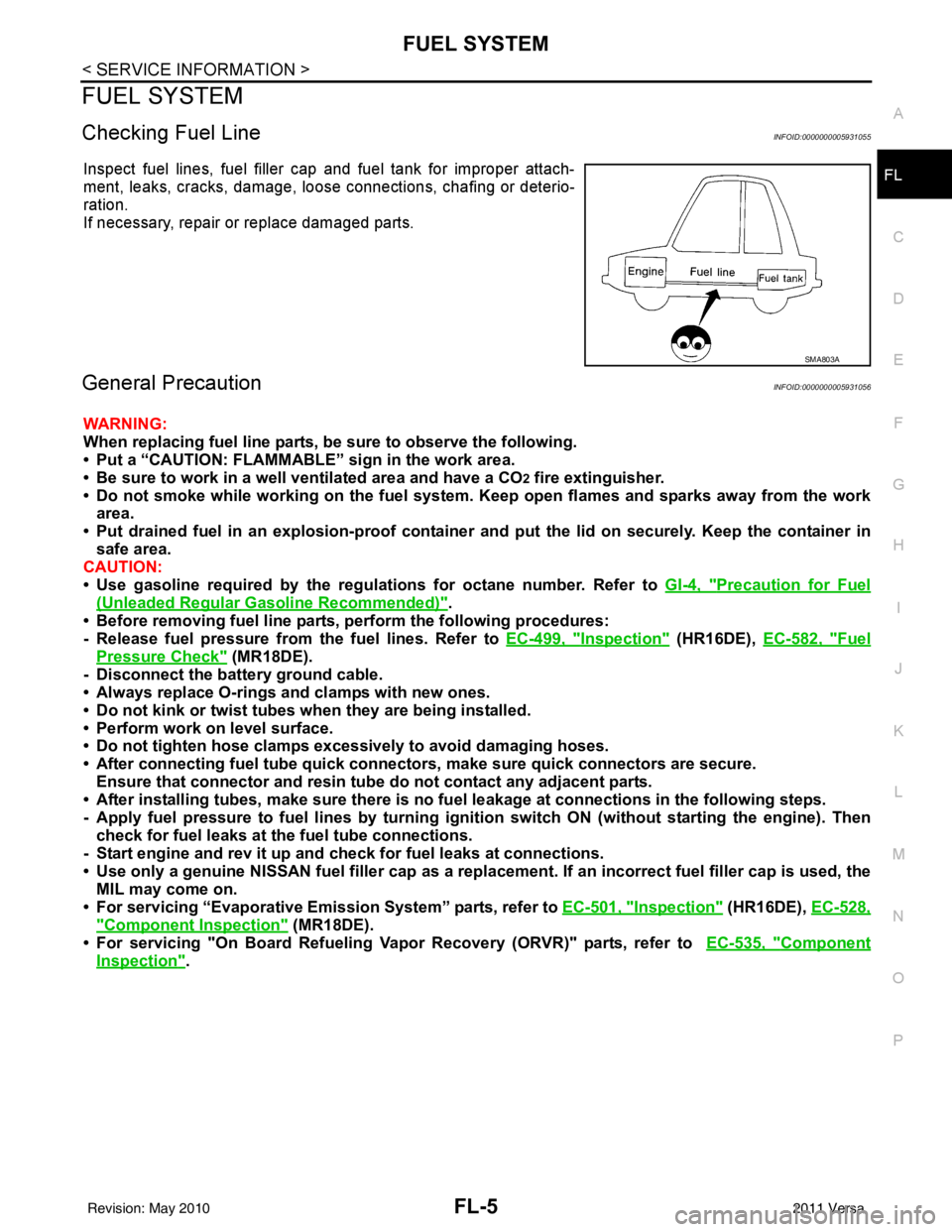
Inspect fuel lines, fuel filler cap and fuel tank for improper attach-
ment, leaks, cracks, damage, loos
e connections, chafing or deterio-
ration.
If necessary, repair or replace damaged parts.
General PrecautionINFOID:0000000005931056
WARNING:
When replacing fuel line parts, be sure to observe the following.
• Put a “CAUTION: FLAMMABLE” sign in the work area.
• Be sure to work in a well ventilated area and have a CO
2 fire extinguisher.
• Do not smoke while working on the fuel system. Keep open flames and sparks away from the work area.
• Put drained fuel in an explosion-proof containe r and put the lid on securely. Keep the container in
safe area.
CAUTION:
• Use gasoline required by the regulations for octane number. Refer to GI-4, "
Precaution for Fuel
(Unleaded Regular Gasoline Recommended)".
• Before removing fuel line parts, perform the following procedures:
- Release fuel pressure from the fuel lines. Refer to EC-499, "
Inspection" (HR16DE), EC-582, "Fuel
Pressure Check" (MR18DE).
- Disconnect the battery ground cable.
• Always replace O-rings and clamps with new ones.
• Do not kink or twist tubes when they are being installed.
• Perform work on level surface.
• Do not tighten hose clamps excessi vely to avoid damaging hoses.
• After connecting fuel tube quick connector s, make sure quick connectors are secure.
Ensure that connector and resin tube do not contact any adjacent parts.
• After installing tubes, make sure there is no fu el leakage at connections in the following steps.
- Apply fuel pressure to fuel lin es by turning ignition switch ON (without starting the engine). Then
check for fuel leaks at the fuel tube connections.
- Start engine and rev it up and check for fuel leaks at connections.
• Use only a genuine NISSAN fuel filler cap as a replacemen t. If an incorrect fuel filler cap is used, the
MIL may come on.
• For servicing “Evaporative Emission System” parts, refer to EC-501, "
Inspection" (HR16DE), EC-528,
"Component Inspection" (MR18DE).
• For servicing "On Board Refueling Vapo r Recovery (ORVR)" parts, refer to EC-535, "
Component
Inspection".
SMA803A
Revision: May 2010 2011 Versa
Page 2673 of 3787

FL-6
< SERVICE INFORMATION >
FUEL LEVEL SENSOR UNIT, FUEL FILTER AND FUEL PUMP ASSEMBLY
FUEL LEVEL SENSOR UNIT, FUEL FILTER AND FUEL PUMP ASSEMBLY
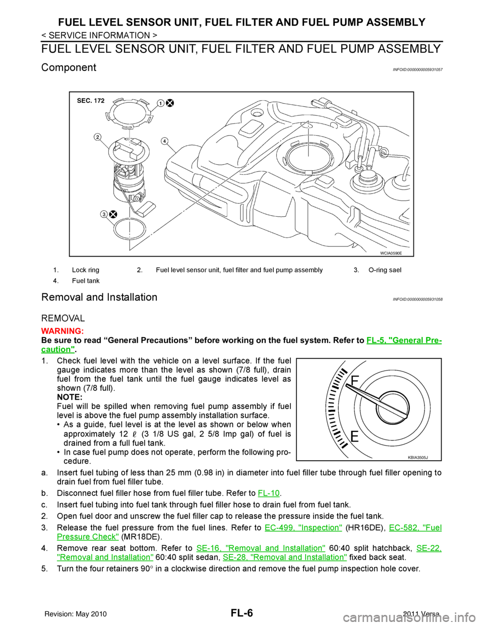
ComponentINFOID:0000000005931057
Removal and InstallationINFOID:0000000005931058
REMOVAL
WARNING:
Be sure to read “General Precautions” be fore working on the fuel system. Refer to FL-5, "
General Pre-
caution".
1. Check fuel level with the vehicle on a level surface. If the fuel gauge indicates more than the level as shown (7/8 full), drain
fuel from the fuel tank until the fuel gauge indicates level as
shown (7/8 full).
NOTE:
Fuel will be spilled when removing fuel pump assembly if fuel
level is above the fuel pump assembly installation surface.
• As a guide, fuel level is at the level as shown or below when
approximately 12 (3 1/8 US gal, 2 5/8 Imp gal) of fuel is
drained from a full fuel tank.
• In case fuel pump does not operate, perform the following pro- cedure.
a. Insert fuel tubing of less than 25 mm (0.98 in) in di ameter into fuel filler tube through fuel filler opening to
drain fuel from fuel filler tube.
b. Disconnect fuel filler hose from fuel filler tube. Refer to FL-10
.
c. Insert fuel tubing into fuel tank through f uel filler hose to drain fuel from fuel tank.
2. Open fuel door and unscrew the fuel filler cap to release the pressure inside the fuel tank.
3. Release the fuel pressure from the fuel lines. Refer to EC-499, "
Inspection" (HR16DE), EC-582, "Fuel
Pressure Check" (MR18DE).
4. Remove rear seat bottom. Refer to SE-16, "
Removal and Installation" 60:40 split hatchback, SE-22,
"Removal and Installation" 60:40 split sedan, SE-28, "Removal and Installation" fixed back seat.
5. Turn the four retainers 90 ° in a clockwise direction and remove the fuel pump inspection hole cover.
1. Lock ring 2. Fuel level sensor unit, fuel filter and fuel pump assembly 3. O-ring sael
4. Fuel tank
WCIA0590E
KBIA3505J
Revision: May 2010 2011 Versa
Page 2677 of 3787

FL-10
< SERVICE INFORMATION >
FUEL TANK
FUEL TANK
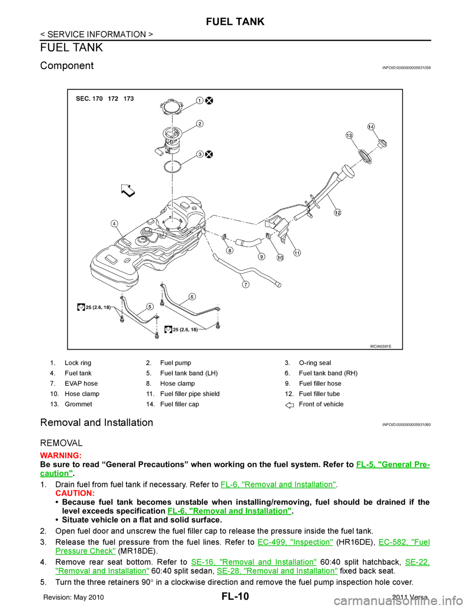
ComponentINFOID:0000000005931059
Removal and InstallationINFOID:0000000005931060
REMOVAL
WARNING:
Be sure to read “General Precautions” when working on the fuel system. Refer to FL-5, "
General Pre-
caution".
1. Drain fuel from fuel tank if necessary. Refer to FL-6, "
Removal and Installation".
CAUTION:
• Because fuel tank becomes unstable when installing/removing, fuel should be drained if the
level exceeds specification FL-6, "
Removal and Installation".
• Situate vehicle on a flat and solid surface.
2. Open fuel door and unscrew the fuel filler cap to release the pressure inside the fuel tank.
3. Release the fuel pressure from the fuel lines. Refer to EC-499, "
Inspection" (HR16DE), EC-582, "Fuel
Pressure Check" (MR18DE).
4. Remove rear seat bottom. Refer to SE-16, "
Removal and Installation" 60:40 split hatchback, SE-22,
"Removal and Installation" 60:40 split sedan, SE-28, "Removal and Installation" fixed back seat.
5. Turn the three retainers 90 ° in a clockwise direction and remove the fuel pump inspection hole cover.
1. Lock ring 2. Fuel pump 3. O-ring seal
4. Fuel tank 5. Fuel tank band (LH) 6. Fuel tank band (RH)
7. EVAP hose 8. Hose clamp 9. Fuel filler hose
10. Hose clamp 11. Fuel filler pipe shield 12. Fuel filler tube
13. Grommet 14. Fuel filler cap Front of vehicle
WCIA0591E
Revision: May 2010 2011 Versa
Page 2707 of 3787

PRECAUTIONSGI-3
< SERVICE INFORMATION >
C
DE
F
G H
I
J
K L
M B
GI
N
O P
2. Use the Intelligent Key or mechanical key to turn the ignition switch to the ″ACC ″ position. At this time, the
steering lock will be released.
3. Disconnect both battery cables. The steering lock will remain released and the steering wheel can be
rotated.
4. Perform the necessary repair operation.
5. When the repair work is completed, return the ignition switch to the ″LOCK ″ position before connecting
the battery cables. (At this time, the steering lock mechanism will engage.)
6. Perform a self-diagnosis check of al l control units using CONSULT-III.
General PrecautionINFOID:0000000005929711
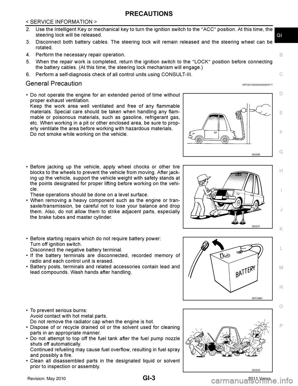
• Do not operate the engine for an extended period of time without
proper exhaust ventilation.
Keep the work area well ventilated and free of any flammable
materials. Special care should be taken when handling any flam-
mable or poisonous materials, such as gasoline, refrigerant gas,
etc. When working in a pit or ot her enclosed area, be sure to prop-
erly ventilate the area before working with hazardous materials.
Do not smoke while working on the vehicle.
• Before jacking up the vehicle, apply wheel chocks or other tire blocks to the wheels to prevent t he vehicle from moving. After jack-
ing up the vehicle, support the vehicle weight with safety stands at
the points designated for proper lifting before working on the vehi-
cle.
These operations should be done on a level surface.
• When removing a heavy component such as the engine or tran-
saxle/transmission, be careful not to lose your balance and drop
them. Also, do not allow them to strike adjacent parts, especially
the brake tubes and master cylinder.
• Before starting repairs which do not require battery power: Turn off ignition switch.
Disconnect the negative battery terminal.
• If the battery terminals are disconnected, recorded memory of
radio and each control unit is erased.
• Battery posts, terminals and related accessories contain lead and lead compounds. Wash hands after handling.
• To prevent serious burns: Avoid contact with hot metal parts.
Do not remove the radiator cap when the engine is hot.
• Dispose of or recycle drained oil or the solvent used for cleaning
parts in an appropriate manner.
• Do not attempt to top off the fuel tank after the fuel pump nozzle shuts off automatically.
Continued refueling may cause fuel overflow, resulting in fuel spray
and possibly a fire.
• Clean all disassembled parts in the designated liquid or solvent
prior to inspection or assembly.
SGI285
SGI231
SEF289H
SGI233
Revision: May 2010 2011 Versa