service indicator NISSAN LATIO 2011 Service Repair Manual
[x] Cancel search | Manufacturer: NISSAN, Model Year: 2011, Model line: LATIO, Model: NISSAN LATIO 2011Pages: 3787, PDF Size: 78.35 MB
Page 18 of 3787

AT-1
TRANSMISSION/TRANSAXLE
DE
F
G H
I
J
K L
M
SECTION AT
A
B
AT
N
O P
CONTENTS
AUTOMATIC TRANSAXLE
SERVICE INFORMATION .. ..........................5
INDEX FOR DTC ............................................ .....5
Alphabetical Index ............................................... ......5
DTC No. Index ..........................................................5
PRECAUTIONS ...................................................7
Precaution for Supplemental Restraint System
(SRS) "AIR BAG" and "SEAT BELT PRE-TEN-
SIONER" ............................................................. ......
7
Precaution Necessary for Steering Wheel Rota-
tion After Battery Disconnect ............................... ......
7
Precaution for On Board Diagnosis (OBD) System
of A/T and Engine .....................................................
8
Precaution .................................................................8
Service Notice or Precaution .....................................9
PREPARATION ..................................................11
Special Service Tool ........................................... ....11
Commercial Service Tool ........................................14
A/T FLUID ...........................................................17
Checking A/T Fluid ..................................................17
Changing A/T Fluid .................................................17
A/T Fluid Cooler Cleaning .......................................18
A/T CONTROL SYSTEM ....................................21
Cross-Sectional View ..............................................21
Shift Mechanism .................................................. ....22
TCM Function ..........................................................30
CAN Communication ...............................................31
Input/Output Signal of TCM .....................................31
Line Pressure Control .............................................32
Shift Control ........................................................ ....33
Lock-up Control .......................................................34
Engine Brake Control (Overrun Clutch Control) ......35
Control Valve ....................................................... ....37
Centrifugal Cancel Mechanism ...............................37
ON BOARD DIAGNOSTIC (OBD) SYSTEM ......39
Introduction ......................................................... ....39
OBD-II Function for A/T System ..............................39
One or Two Trip Detection Logic of OBD-II ......... ....39
OBD-II Diagnostic Trouble Code (DTC) ..................39
Malfunction Indicator Lamp (MIL) ............................41
TROUBLE DIAGNOSIS ....................................42
DTC Inspection Priority Chart ..................................42
Fail-Safe ..................................................................42
How to Perform Trouble Diagnosis for Quick and
Accurate Repair .......................................................
43
A/T Electrical Parts Location ...................................49
Circuit Diagram ........................................................50
Inspections Before Trouble Diagnosis .....................51
Road Test ................................................................55
Check Before Engine Is Started ..............................56
Check at Idle ............................................................56
Cruise Test - Part 1 .................................................58
Cruise Test - Part 2 .................................................61
Cruise Test - Part 3 .................................................62
Vehicle Speed at Which Gear Shifting Occurs ........64
Vehicle Speed at Which Lock-up Occurs/Releas-
es .............................................................................
64
Symptom Chart ........................................................65
TCM Terminal and Reference Value .......................75
CONSULT-III Function (TRANSMISSION) .......... ....77
Diagnosis Procedure without CONSULT-III ............82
U1000 CAN COMM CIRCUIT ...........................87
Description ........................................................... ....87
On Board Diagnosis Logic .......................................87
Possible Cause ........................................................87
DTC Confirmation Procedure ..................................87
Wiring Diagram - AT - CAN .....................................88
Diagnosis Procedure ...............................................89
P0705 TRANSMISSION RANGE SWITCH A ...90
Description ...............................................................90
CONSULT-III Reference Value in Data Monitor
Mode .................................................................... ....
90
On Board Diagnosis Logic .......................................90
Possible Cause ........................................................90
DTC Confirmation Procedure ..................................90
Revision: May 2010 2011 Versa
Page 20 of 3787

AT-3
DE
F
G H
I
J
K L
M A
B
AT
N
O
P
N
P1760 OVERRUN CLUTCH
SOLENOID .........148
Description .......................................................... ..148
CONSULT-III Reference Value in Data Monitor
Mode ................................................................... ..
148
On Board Diagnosis Logic ....................................148
Possible Cause .....................................................148
DTC Confirmation Procedure ................................148
Wiring Diagram - AT - OVRCSV ...........................149
Diagnosis Procedure .............................................150
Component Inspection ..........................................151
VEHICLE SPEED SIGNAL ...............................153
Description .......................................................... ..153
CONSULT-III Reference Value in Data Monitor
Mode ................................................................... ..
153
On Board Diagnosis Logic ....................................153
Possible Cause .....................................................153
DTC Confirmation Procedure ................................153
Wiring Diagram - AT - VSSMTR ...........................154
Diagnosis Procedure ........................................... ..155
BATT/FLUID TEMP SEN .................................156
Description .......................................................... ..156
CONSULT-III Reference Value in Data Monitor
Mode ................................................................... ..
156
On Board Diagnosis Logic ....................................156
Possible Cause .....................................................156
DTC Confirmation Procedure ................................156
Wiring Diagram - AT - BA/FTS ..............................157
Diagnosis Procedure .............................................158
Component Inspection ..........................................160
INPUT SPEED SENSOR A ..............................162
Description .......................................................... ..162
CONSULT-III Reference Value in Data Monitor
Mode ................................................................... ..
162
On Board Diagnosis Logic ....................................162
Possible Cause .....................................................162
DTC Confirmation Procedure ................................162
Wiring Diagram - AT - PT/SEN .............................163
Diagnosis Procedure .............................................164
CONTROL UNIT (RAM), CONTROL UNIT
(ROM) ...............................................................
167
Description .......................................................... ..167
On Board Diagnosis Logic ....................................167
Possible Cause .....................................................167
DTC Confirmation Procedure ................................167
Diagnosis Procedure .............................................167
MAIN POWER SUPPLY AND GROUND CIR-
CUIT ..................................................................
168
Wiring Diagram - AT - MAIN ............................... ..168
Diagnosis Procedure .............................................169
TR SW, OD SW AND CLOSED THROTTLE,
WIDE OPEN THROTTLE POSITION SIGNAL
CIRCUIT ......................................................... ..
171
CONSULT-III Reference Value in Data Monitor
Mode ................................................................... ..
171
TCM Terminal and Reference Value .....................171
Diagnosis Procedure ........................................... ..171
Component Inspection ...........................................175
SHIFT POSITION INDICATOR CIRCUIT ........176
Description .............................................................176
CONSULT-III Reference Value in Data Monitor
Mode .................................................................... ..
176
Diagnosis Procedure .............................................176
TROUBLE DIAGNOSIS FOR SYMPTOMS ....177
Wiring Diagram - AT - NONDTC ...........................177
OD OFF Indicator Lamp Does Not Come On ........180
Engine Cannot Be Started in "P" and "N" Position ..182
In "P" Position, Vehicle Moves Forward or Back-
ward When Pushed ...............................................
183
In "N" Position, Vehicle Moves ..............................183
Large Shock "N" → "R" Position .......................... ..184
Vehicle Does Not Creep Backward in "R" Position ..185
Vehicle Does Not Creep Forward in "D", "2" or "1"
Position ................................................................ ..
186
Vehicle Cannot Be Started from D1 .......................187
A/T Does Not Shift: D1→ D2or Does Not Kick-
down: D
4→ D2 ..................................................... ..189
A/T Does Not Shift: D2→ D3 ................................ ..190
A/T Does Not Shift: D3→ D4 ................................ ..192
A/T Does Not Perform Lock-up ........................... ..193
A/T Does Not Hold Lock-up Condition ...................194
Lock-up Is Not Released .......................................195
Engine Speed Does Not Return to Idle (Light
Braking D
4→ D3) ................................................. ..196
A/T Does Not Shift: D4→ D3, When OD OFF ...... ..197
A/T Does Not Shift: D3→ 22, When Selector Lever
"D" → "2" Position ............................................... ..
198
A/T Does Not Shift: 22→ 11, When Selector Lever
"2" → "1" Position ................................................ ..
199
Vehicle Does Not Decelerate by Engine Brake ... ..201
TCM Self-Diagnosis Does Not Activate .................204
A/T SHIFT LOCK SYSTEM .............................206
Description .............................................................206
Shift Lock System Parts Location ..........................207
Wiring Diagram - AT - SHIFT ................................208
Diagnosis Procedure .............................................208
TRANSMISSION CONTROL MODULE ..........212
Removal and Installation .......................................212
SHIFT CONTROL SYSTEM ............................213
A/T Shift Selector Removal and Installation ........ ..213
A/T Shift Selector Disassembly and Assembly ......216
Shift Selector Handle Removal and Installation ....216
Adjustment of A/T Position ....................................217
Checking of A/T Position .......................................217
KEY INTERLOCK CABLE ..............................219
Removal and Installation .......................................219
ON-VEHICLE SERVICE ..................................222
Control Valve Assembly and Accumulators ...........222
Revision: May 2010 2011 Versa
Page 25 of 3787
AT-8
< SERVICE INFORMATION >
PRECAUTIONS
6. Perform a self-diagnosis check of all control units using CONSULT-III.
Precaution for On Board Diagnosis (OBD) System of A/T and EngineINFOID:0000000005928065
The ECM has an on board diagnostic system. It will light up the malfunction indicator lamp (MIL) to warn the
driver of a malfunction causing emission deterioration.
CAUTION:
• Be sure to turn the ignition switch OFF and disconnect battery negative cable from battery negative
terminal before any repair or inspection work. The open/short circuit of related switches, sensors,
solenoid valves, etc. will cause the MIL to light up.
• Be sure to connect and lock the connectors secure ly after work. A loose (unlocked) connector will
cause the MIL to light up due to an open circuit. (Be sure the connectors are free from water, grease,
dirt, bent terminals, etc.)
• Be sure to route and secure th e harnesses properly after work. Interference of the harness with a
bracket, etc. may cause the MIL to light up due to a short circuit.
• Be sure to erase the unnecessary malfunction informa tion (repairs completed) from the TCM and
ECM before returning the vehicle to the customer.
PrecautionINFOID:0000000005928066
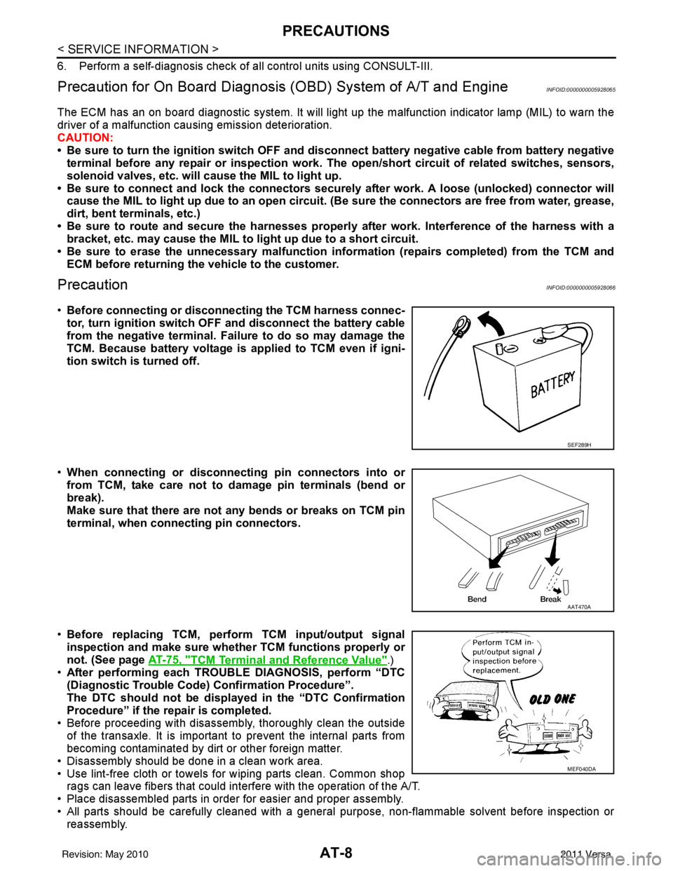
•Before connecting or disconn ecting the TCM harness connec-
tor, turn ignition switch OF F and disconnect the battery cable
from the negative terminal. Failure to do so may damage the
TCM. Because battery voltage is applied to TCM even if igni-
tion switch is turned off.
• When connecting or disconnect ing pin connectors into or
from TCM, take care not to damage pin terminals (bend or
break).
Make sure that there are not any bends or breaks on TCM pin
terminal, when connecting pin connectors.
• Before replacing TCM, perform TCM input/output signal
inspection and make sure whether TCM functions properly or
not. (See page AT-75, "
TCM Terminal and Reference Value".)
• After performing each TROUBLE DIAGNOSIS, perform “DTC
(Diagnostic Trouble Code) Confirmation Procedure”.
The DTC should not be displ ayed in the “DTC Confirmation
Procedure” if the repair is completed.
• Before proceeding with disassembly, thoroughly clean the outside of the transaxle. It is important to prevent the internal parts from
becoming contaminated by dirt or other foreign matter.
• Disassembly should be done in a clean work area.
• Use lint-free cloth or towels for wiping parts clean. Common shop rags can leave fibers that could in terfere with the operation of the A/T.
• Place disassembled parts in order for easier and proper assembly.
• All parts should be carefully cleaned with a general purpose, non-flammable solvent before inspection or reassembly.
SEF289H
AAT470A
MEF040DA
Revision: May 2010 2011 Versa
Page 26 of 3787
PRECAUTIONSAT-9
< SERVICE INFORMATION >
DE
F
G H
I
J
K L
M A
B
AT
N
O P
• Gaskets, seals and O-rings should be replaced any time the A/T is disassembled.
• It is very important to perform func tional tests whenever they are indicated.
• The valve body contains precision parts and requires extreme care when parts are removed and serviced.
Place disassembled valve body parts in order for easier and proper assembly. Care will also prevent springs
and small parts from becoming scattered or lost.
• Properly installed valves, sleeves, plugs, etc. will slide along bores in valve body under their own weight.
• Before assembly, apply a coat of recommended ATF to all parts. Apply petroleum jelly to protect O-rings and seals, or hold bearings and washers in pl ace during assembly. Do not use grease.
• Extreme care should be taken to avoid damage to O-rings, seals and gaskets when assembling.
• Clean or replace ATF cooler if excessive foreign material is found in oil pan or clogging strainer. Refer to AT-
18, "A/T Fluid Cooler Cleaning".
• After overhaul, refill the A/T with new ATF.
• When the A/T drain plug is removed, only some of the fluid is drained. Old A/T fluid will remain in torque con- verter and ATF cooling system.
Always follow the procedures under “Changing A/T Fluid” in the AT section when changing A/T fluid. Refer to
AT-17, "
Changing A/T Fluid", AT-17, "Checking A/T Fluid".
Service Notice or PrecautionINFOID:0000000005928067
ATF COOLER SERVICE
If A/T fluid contains frictional material (clutches, bands, etc.), or if an A/T is repaired, overhauled, or replaced,
inspect and clean the A/T oil cooler mounted in the radiator or replace the radiator. Flush cooler lines using
cleaning solvent and compressed air after repair. Check Service Bulletins for latest A/T oil cooler cleaning pro-
cedure. For radiator replacement, refer to CO-16, "
Removal and Installation" (HR16DE engine models), CO-
40, "Removal and Installation" (MR18DE engine models).
TORQUE CONVERTER SERVICE
The torque converter should be replaced under any of the following conditions:
• External leaks in the hub weld area.
• Converter hub is scored or damaged.
• Converter pilot is broken, damaged or fits poorly into crankshaft.
• Steel particles are found after flushing the cooler and cooler lines.
• Pump is damaged or steel particles are found in the converter.
• Vehicle has TCC shudder and/or no TCC apply. Replace only after all hydraulic and electrical diagnoses
have been made. (Converter clutch material may be glazed.)
• Converter is contaminated with engi ne coolant containing antifreeze.
• Internal malfunction of stator roller clutch.
• Heavy clutch debris due to overheating (blue converter).
• Steel particles or clutch lining material found in flui d filter or on magnet when no internal parts in unit are
worn or damaged — indicates that lining material came from converter.
The torque converter should not be replaced if:
• The fluid has an odor, is discolored, and there is no evidence of metal or clutch facing particles.
• The threads in one or more of the converter bolt holes are damaged.
• A/T malfunction did not display evidence of damaged or worn internal parts, steel particles or clutch plate lin-
ing material in unit and inside the fluid filter.
• Vehicle has been exposed to high mileage (only). The e xception may be where the torque converter clutch
dampener plate lining has seen excess wear by vehicles operated in heavy and/or constant traffic, such as
taxi, delivery or police use.
OBD-II SELF-DIAGNOSIS
• A/T self-diagnosis is performed by the TCM in combination with the ECM. The results can be read through the blinking pattern of the OD OFF indicator lamp or the malfunction indicator lamp (MIL). Refer to the table
on AT-82, "
Diagnosis Procedure without CONSULT-III" for the indicator used to display each self-diagnostic
result.
• The self-diagnostic results indicated by the MIL are automatically stored in both the ECM and TCM memo- ries.
Always perform the procedure “HOW TO ERASE DTC” on AT-39, "
OBD-II Diagnostic Trouble Code
(DTC)" to complete the repair and avoid unnecessary blinking of the MIL.
• The following self-diagnostic items can be detected us ing ECM self-diagnostic results mode* only when the
OD OFF indicator lamp does not indicate any malfunctions.
- Transmission range switch
- A/T 1GR, 2GR, 3GR, or 4GR function
Revision: May 2010 2011 Versa
Page 41 of 3787
AT-24
< SERVICE INFORMATION >
A/T CONTROL SYSTEM
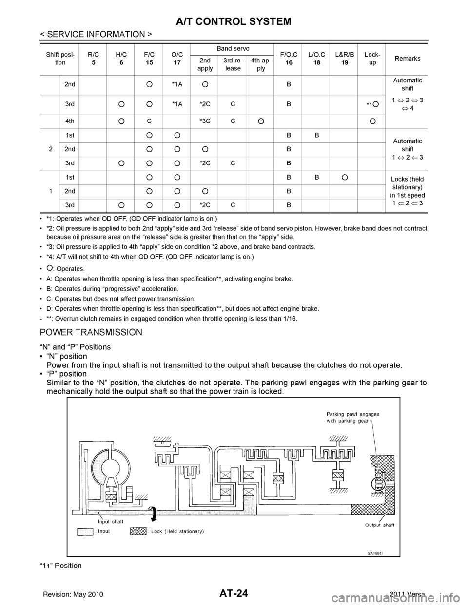
• *1: Operates when OD OFF. (OD OFF indicator lamp is on.)
• *2: Oil pressure is applied to both 2nd “apply” side and 3rd “release” side of band servo piston. However, brake band does not contract
because oil pressure area on the “release” side is greater than that on the “apply” side.
• *3: Oil pressure is applied to 4th “apply” side on condition *2 above, and brake band contracts.
• *4: A/T will not shift to 4th when OD OFF. (OD OFF indicator lamp is on.)
• : Operates.
• A: Operates when throttle opening is less than specification**, activating engine brake.
• B: Operates during “pro gressive” acceleration.
• C: Operates but does not affect power transmission.
• D: Operates when throttle opening is less than specification**, but does not affect engine brake.
- **: Overrun clutch remains in engaged condition when throttle opening is less than 1/16.
POWER TRANSMISSION
“N” and “P” Positions
• “N” position Power from the input shaft is not transmitted to the output shaft because the clutches do not operate.
• “P” position
Similar to the “N” position, the clutches do not operate. The parking pawl engages with the parking gear to
mechanically hold the output shaft so that the power train is locked.
“11” Position
2nd *1A BAutomatic
shift
3rd *1A *2C C B
*11
⇔ 2 ⇔ 3
⇔ 4
4th C*3C C
2 1st
BB
Automatic
shift
1 ⇔ 2 ⇐ 3
2nd
B
3rd *2C CB
1 1st
BB
Locks (held
stationary)
in 1st speed 1 ⇐ 2 ⇐ 3
2nd
B
3rd *2C CB
Shift posi-
tion R/C
5 H/C
6 F/C
15 O/C
17 Band servo
F/O.C
16 L/O.C
18 L&R/B
19 Lock-
up Remarks
2nd
apply 3rd re-
lease 4th ap-
ply
SAT991I
Revision: May 2010 2011 Versa
Page 42 of 3787
A/T CONTROL SYSTEMAT-25
< SERVICE INFORMATION >
DE
F
G H
I
J
K L
M A
B
AT
N
O P
“D
1” and “21” Positions
*: Overrun clutch remains in engaged condition when throttle opening is less than 1/16. •
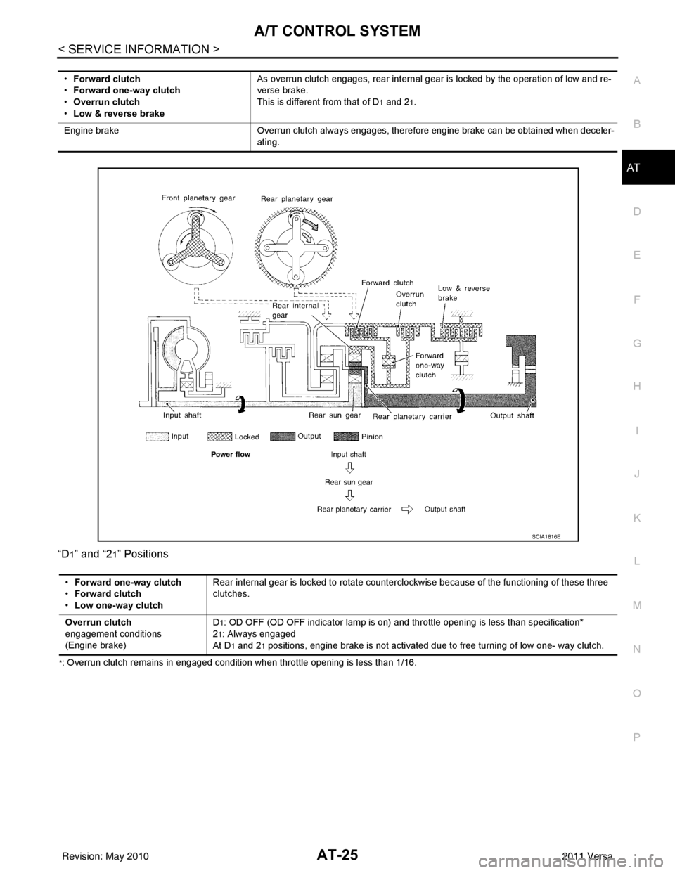
Forward clutch
• Forward one-way clutch
• Overrun clutch
• Low & reverse brake As overrun clutch engages, rear internal gear is locked by the operation of low and re-
verse brake.
This is different from that of D
1 and 21.
Engine brake Overrun clutch always engages, therefore engine brake can be obtained when deceler-
ating.
SCIA1816E
• Forward one-way clutch
• Forward clutch
• Low one-way clutch Rear internal gear is locked to rotate counterclockwise because of the functioning of these three
clutches.
Overrun clutch
engagement conditions
(Engine brake) D
1: OD OFF (OD OFF indicator lamp is on) and th
rottle opening is less than specification*
2
1: Always engaged
At D
1 and 21 positions, engine brake is not activated due to free turning of low one- way clutch.
Revision: May 2010 2011 Versa
Page 43 of 3787
AT-26
< SERVICE INFORMATION >
A/T CONTROL SYSTEM
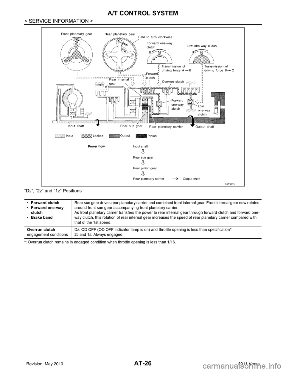
“D2”, “22” and “12” Positions
*: Overrun clutch remains in engaged condition when throttle opening is less than 1/16.
SAT377J
•Forward clutch
• Forward one-way
clutch
• Brake band Rear sun gear drives rear planetary carrier and combined front internal gear. Front internal gear now rotates
around front sun gear accompanying front planetary carrier.
As front planetary carrier transfers the power to rear internal gear through forward clutch and forward one-
way clutch, this rotation of rear internal gear increases the speed of rear planetary carrier compared with
that of the 1st speed.
Overrun clutch
engagement conditions D
2: OD OFF (OD OFF indicator lamp is on) and throttle opening is less than specification*
2
2 and 12: Always engaged
Revision: May 2010 2011 Versa
Page 44 of 3787
A/T CONTROL SYSTEMAT-27
< SERVICE INFORMATION >
DE
F
G H
I
J
K L
M A
B
AT
N
O P
“D
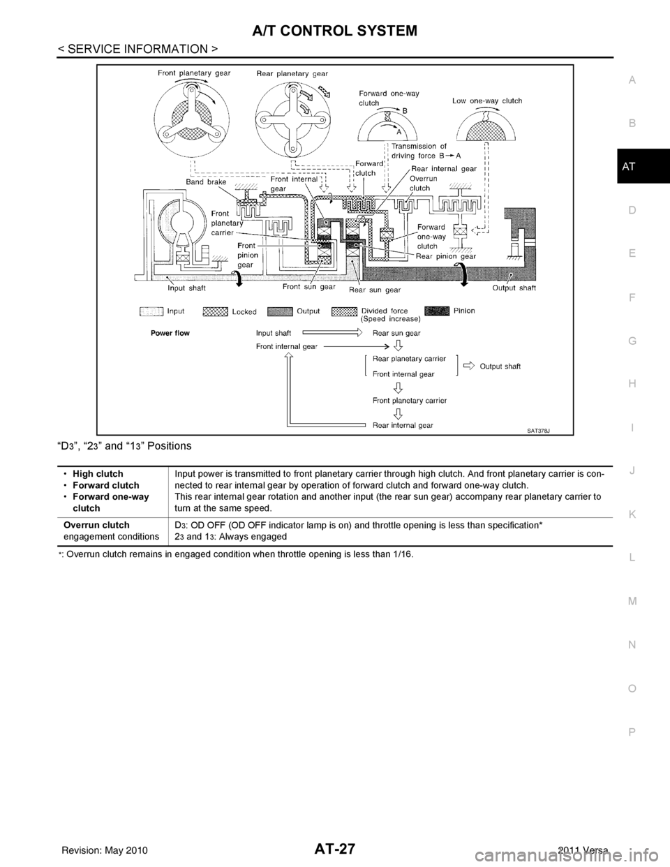
3”, “23” and “13” Positions
*: Overrun clutch remains in engaged condition when throttle opening is less than 1/16.
SAT378J
•
High clutch
• Forward clutch
• Forward one-way
clutch Input power is transmitted to front planetary carrier through high clutch. And front planetary carrier is con-
nected to rear internal gear by operation of forward clutch and forward one-way clutch.
This rear internal gear rotation and another input (the rear sun gear) accompany rear planetary carrier to
turn at the same speed.
Overrun clutch
engagement conditions D
3: OD OFF (OD OFF indicator lamp is on) and throttle opening is less than specification*
2
3 and 13: Always engaged
Revision: May 2010 2011 Versa
Page 47 of 3787
AT-30
< SERVICE INFORMATION >
A/T CONTROL SYSTEM
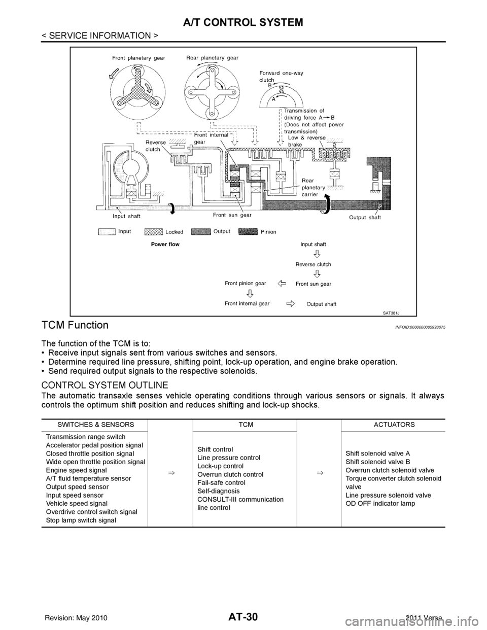
TCM Function
INFOID:0000000005928075
The function of the TCM is to:
• Receive input signals sent from various switches and sensors.
• Determine required line pressure, shifting poi nt, lock-up operation, and engine brake operation.
• Send required output signals to the respective solenoids.
CONTROL SYSTEM OUTLINE
The automatic transaxle senses vehicle operating conditions through various sensors or signals. It always
controls the optimum shift position and reduces shifting and lock-up shocks.
SAT381J
SWITCHES & SENSORS
⇒TCM
⇒ACTUATORS
Transmission range switch
Accelerator pedal position signal
Closed throttle position signal
Wide open throttle position signal
Engine speed signal
A/T fluid temperature sensor
Output speed sensor
Input speed sensor
Vehicle speed signal
Overdrive control switch signal
Stop lamp switch signal Shift control
Line pressure control
Lock-up control
Overrun clutch control
Fail-safe control
Self-diagnosis
CONSULT-III communication
line control
Shift solenoid valve A
Shift solenoid valve B
Overrun clutch solenoid valve
Torque converter clutch solenoid
valve
Line pressure solenoid valve
OD OFF indicator lamp
Revision: May 2010
2011 Versa
Page 49 of 3787
AT-32
< SERVICE INFORMATION >
A/T CONTROL SYSTEM
*1: Output speed sensor
*2: Spare for accelerator pedal position signal
*3: If these input and output signals are different, the TCM triggers the fail-safe function.
*4: Used as a condition for starting self-diagnostics; if self-diagnosis are not started, it is judged that there is some kind of error.
*5: Input by CAN communications.
*6: Output by CAN communications.
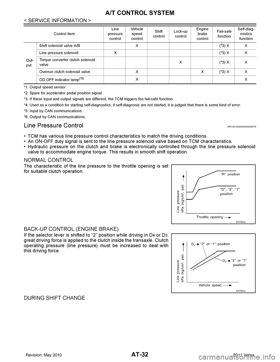
Line Pressure ControlINFOID:0000000005928078
• TCM has various line pressure control char acteristics to match the driving conditions.
• An ON-OFF duty signal is sent to the line pres sure solenoid valve based on TCM characteristics.
• Hydraulic pressure on the clutch and brake is electronically controlled through the line pressure solenoid valve to accommodate engine torque. This results in smooth shift operation.
NORMAL CONTROL
The characteristic of the line pressure to the throttle opening is set
for suitable clutch operation.
BACK-UP CONTROL (ENGINE BRAKE)
If the selector lever is shifted to “2” position while driving in D4 or D3,
great driving force is applied to the clutch inside the transaxle. Clutch
operating pressure (line pressure) must be increased to deal with
this driving force.
DURING SHIFT CHANGE
Out-
put Shift solenoid valve A/B
X(*3) X X
Line pressure solenoid X (*3) X X
Torque converter clutch solenoid
valve X(
*3 ) X X
Overrun clutch solenoid valve XX (*3) X X
OD OFF indicator lamp
(*6)XX
Control item
Line
pressure
control Vehicle
speed
control Shift
control Lock-up
control Engine
brake
control Fail-safe
function Self-diag-
nostics
function
SAT003J
SAT004J
Revision: May 2010 2011 Versa