mirror NISSAN LEAF 2022 Owner´s Manual
[x] Cancel search | Manufacturer: NISSAN, Model Year: 2022, Model line: LEAF, Model: NISSAN LEAF 2022Pages: 618, PDF Size: 4.3 MB
Page 311 of 618
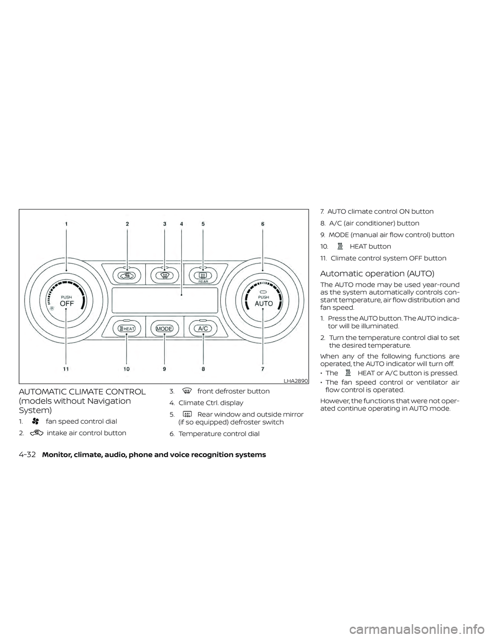
AUTOMATIC CLIMATE CONTROL
(models without Navigation
System)
1.fan speed control dial
2.
intake air control button 3.
front defroster button
4. Climate Ctrl. display
5.
Rear window and outside mirror
(if so equipped) defroster switch
6. Temperature control dial 7. AUTO climate control ON button
8. A/C (air conditioner) button
9. MODE (manual air flow control) button
10.
HEAT button
11. Climate control system OFF button
Automatic operation (AUTO)
The AUTO mode may be used year-round
as the system automatically controls con-
stant temperature, air flow distribution and
fan speed.
1. Press the AUTO button. The AUTO indica- tor will be illuminated.
2. Turn the temperature control dial to set the desired temperature.
When any of the following functions are
operated, the AUTO indicator will turn off.
• The
HEAT or A/C button is pressed.
• The fan speed control or ventilator air flow control is operated.
However, the functions that were not oper-
ated continue operating in AUTO mode.LHA2890
4-32Monitor, climate, audio, phone and voice recognition systems
Page 314 of 618
To set the automatic control mode, press
and hold theintake air control button.
The indicator light will blink twice and the
inside/outside circulation will then be con-
trolled automatically. When in automatic
mode, the indicator light will come on when
inside air recirculation is active.
Rear window and outside mirror (if so
equipped) defroster switch
For additional information, see “Rear win-
dow and outside mirror (if so equipped)
defroster switch” (P. 2-47).
To turn the system off
To turn off the climate control, press the
Climate control system OFF button. The
same operating mode (Heater or A/C) that
was active when the system is turned off is
active when system is turned back on.
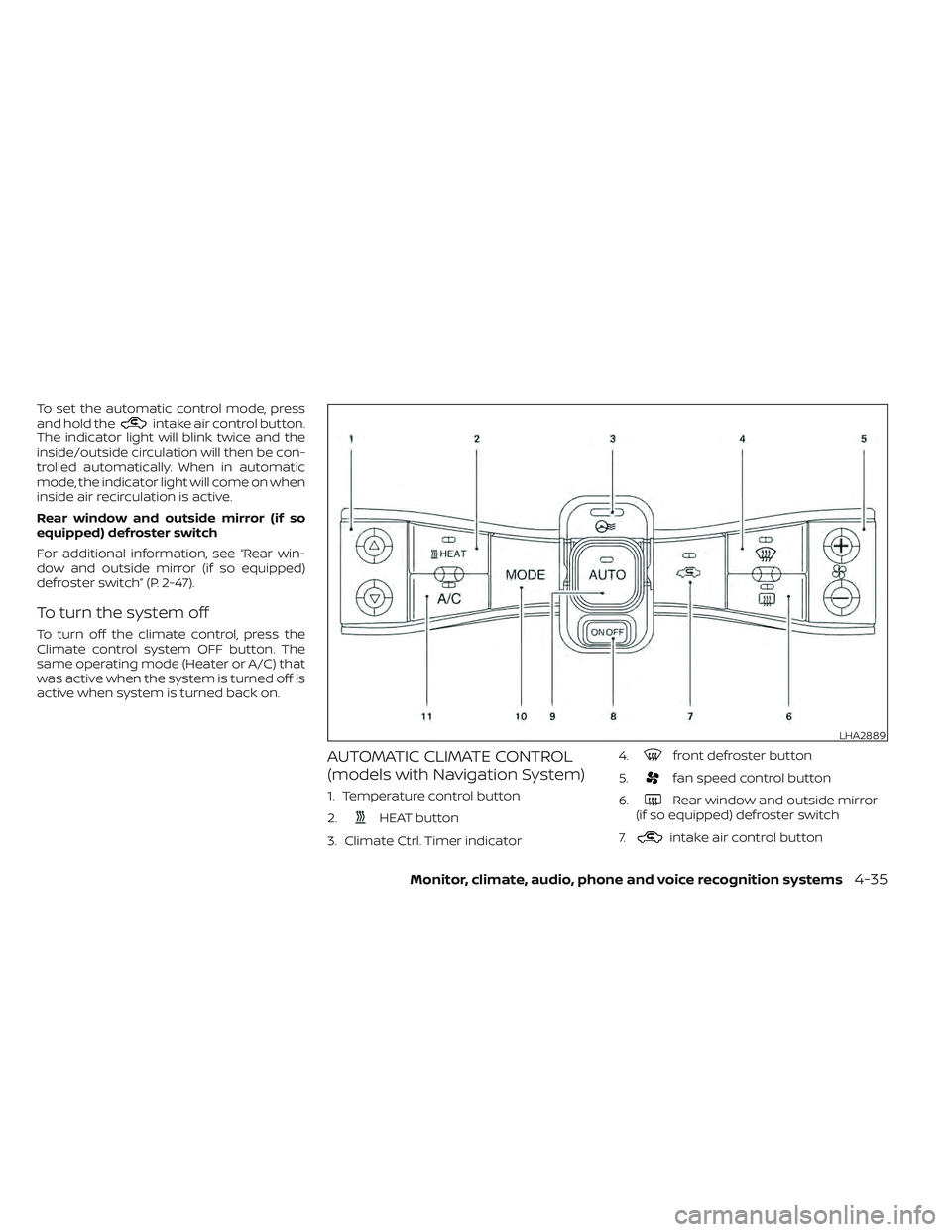
AUTOMATIC CLIMATE CONTROL
(models with Navigation System)
1. Temperature control button
2.
HEAT button
3. Climate Ctrl. Timer indicator 4.
front defroster button
5.
fan speed control button
6.
Rear window and outside mirror
(if so equipped) defroster switch
7.
intake air control button
LHA2889
Monitor, climate, audio, phone and voice recognition systems4-35
Page 317 of 618
Temperature control
Press the temperature control buttons to
set the desired temperature.
Air recirculation
Press the
intake air control button to
change the air circulation mode. When the
indicator light illuminates, the flowing air is
recirculated inside the vehicle.
When the outside temperature exceeds
70°F (21°C) the air conditioning system may
default to air recirculation mode automati-
cally to reduce overall power consumption.
To exit air recirculation mode, deselect the
air recirculation button (indicator will turn
off ) to enter fresh mode.
Outside air circulation
Press the
intake air control button to
change the air circulation mode. When the
indicator light does not illuminate, the flow-
ing air is drawn from outside the vehicle.
Automatic air intake control
In the AUTO mode, the intake air will be
controlled automatically. When the outside
temperature exceeds 70°F (21°C), the air
conditioning system may default to air re-
circulation mode automatically to reduce
overall power consumption. To set the automatic control mode, press
and hold the
intake air control button.
The indicator light will blink twice and the
inside/outside circulation will then be con-
trolled automatically. When in automatic
mode, the indicator light will come on when
inside air recirculation is active.
Rear window and outside mirror (if so
equipped) defroster switch
For additional information, see “Rear win-
dow and outside mirror (if so equipped)
defroster switch” (P. 2-47).
To turn the system off
To turn off the climate control, press the
Climate control system ON·OFF button.
The same operating mode (Heater or A/C)
that was active when the system is turned
off is active when system is turned back on.
CLIMATE CTRL. TIMER
This function pre-heats or pre-cools the
passenger compartment of the vehicle to
the temperature before driving. This helps
reduce power consumption from the Li-ion
battery.
The Climate Ctrl. Timer operates the air
conditioner using power from the charger
or the Li-ion battery. While the charging connector is connected to the vehicle,
electric power from the Li-ion battery is not
used.
The Climate Ctrl. Timer function allows two
timer settings.
Once the Climate Ctrl. Timer is set, it will
complete air conditioning by the time that
is set. It is not necessary to set the Climate
Ctrl. Timer every day.
WARNING
Even if the Climate Ctrl. Timer is set, the
temperature in the passenger com-
partment may become high or low if
the system automatically stops. Do not
leave children or adults who would nor-
mally require the support of others
alone in your vehicle. Pets should not
be lef t alone either. On hot, sunny days,
temperatures in a closed vehicle could
quickly become high enough to cause
severe or possibly fatal injuries to
people or animals. Also on cold days,
temperature in a vehicle could become
low enough to cause severe or possible
fatal injuries to people or animals.
4-38Monitor, climate, audio, phone and voice recognition systems
Page 338 of 618
4. Push the power switch while depressingthe brake pedal within 10 seconds af ter
the chime sounds. The power switch
position changes to the READY to drive
mode.
Af ter step 3 is performed, if the power
switch is pushed without depressing the
brake pedal, the power switch position will
change to ACC.
NOTE:
• When the power switch is placed in the ACC or ON position or READY to drive
mode by the above procedure, the EV
system operation for discharged Intel-
ligent Key system indicator appears on
the vehicle information display even if
the Intelligent Key is inside the vehicle.
This is not a malfunction. To stop the
warning indicator from blinking, touch
the power switch with the Intelligent
Key again.
• If the Intelligent Key battery discharge indicator appears on the vehicle infor-
mation display, replace the battery as
soon as possible. For additional infor-
mation, see “NISSAN Intelligent Key®
battery replacement” (P. 8-19).
NISSAN VEHICLE IMMOBILIZER
SYSTEM
The NISSAN Vehicle Immobilizer System
will not allow the power switch to be placed
in the READY to drive position without the
use of the registered key.
If the power switch fails to place the vehicle
into the READY to drive position using the
registered key, it may be due to interfer-
ence caused by another registered key, an
automated toll road device or automated
payment device on the key ring. Restart the
EV system using the following procedure:
1. Leave the power switch in the ON posi- tion for approximately 5 seconds.
2. Place the power switch in the OFF posi- tion and wait approximately 10 seconds.
3. Repeat steps 1 and 2 again.
4. Place the power switch in the READY to drive position while holding the device
(which may have caused the interfer-
ence) separate from the registered key.
If this procedure allows the power
switch to be placed in the READY to drive
mode, NISSAN recommends placing the
registered key on a separate key ring to
avoid interference from other devices. • Make sure that the area around the ve-
hicle is clear.
• Check fluid levels such as coolant, brake fluid, and windshield-washer fluid as fre-
quently as possible.
• Check that all windows and lights are clean.
• Visually inspect tires for their appearance and condition. Also check tires for proper
inflation.
• Check that all doors are closed.
• Position the seat and adjust the head restraints/headrests.
• Adjust the inside and outside mirrors.
• Fasten seat belts and ask all passengers to do likewise.
• Check the operation of the warning lights when the power switch is pushed to the
ON position. For additional information,
see “Warning lights, indicator lights and
audible reminders” (P. 2-14).
BEFORE STARTING THE EV SYSTEM
Starting and driving5-13
Page 350 of 618
WARNING
Failure to follow the warnings and in-
structions for proper use of the LDW
system could result in serious injury or
death.
• This system is only a warning device
to inform the driver of a potential un-
intended lane departure. It will not
steer the vehicle or prevent loss of
control. It is the driver’s responsibility
to stay alert, drive safely, keep the
vehicle in the traveling lane, and be in
control of the vehicle at all times. The LDW system will operate when the ve-
hicle is driven at speeds of approximately
37 mph (60 km/h) and above, and only
when the lane markings are clearly visible
on the road.
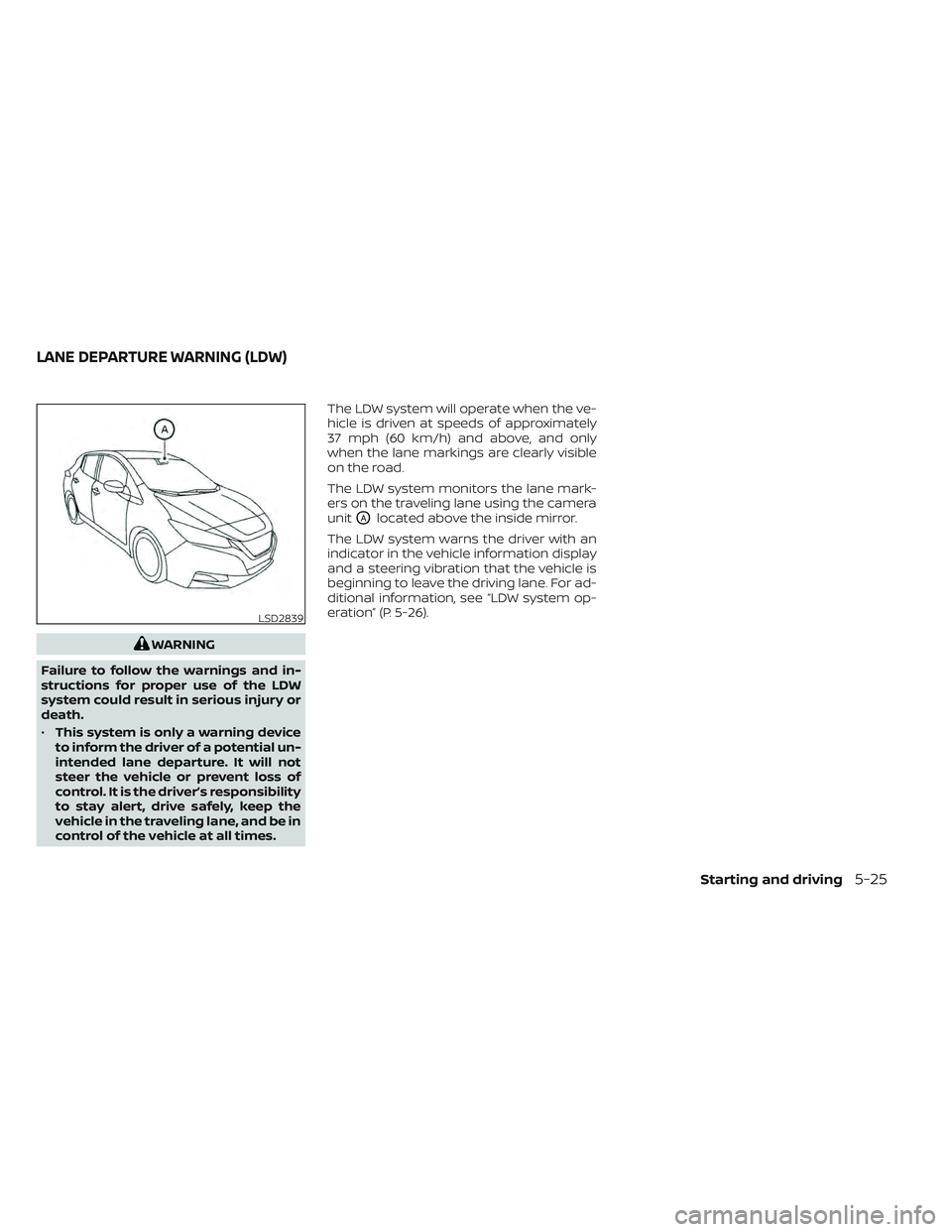
The LDW system monitors the lane mark-
ers on the traveling lane using the camera
unit
OAlocated above the inside mirror.
The LDW system warns the driver with an
indicator in the vehicle information display
and a steering vibration that the vehicle is
beginning to leave the driving lane. For ad-
ditional information, see “LDW system op-
eration” (P. 5-26).
LSD2839
LANE DEPARTURE WARNING (LDW)
Starting and driving5-25
Page 354 of 618
Af ter the above conditions have finished
and the necessary operating conditions
are satisfied, the LDW functions will resume.
SYSTEM MALFUNCTION
If the LDW system malfunctions, it will can-
cel automatically and “Malfunction: See
Owner’s Manual” will appear in the vehicle
information display. If “Malfunction: See
Owner’s Manual” appears in the vehicle in-
formation display, pull off the road to a safe
location and stop the vehicle. Place the
shif t lever in the P (Park) position and the
power switch in the OFF position and re-
start the EV system. If “Malfunction: See
Owner’s Manual” continues to appear in
the vehicle information display, have the
system checked. It is recommended that
you visit a NISSAN certified LEAF dealer for
this service.
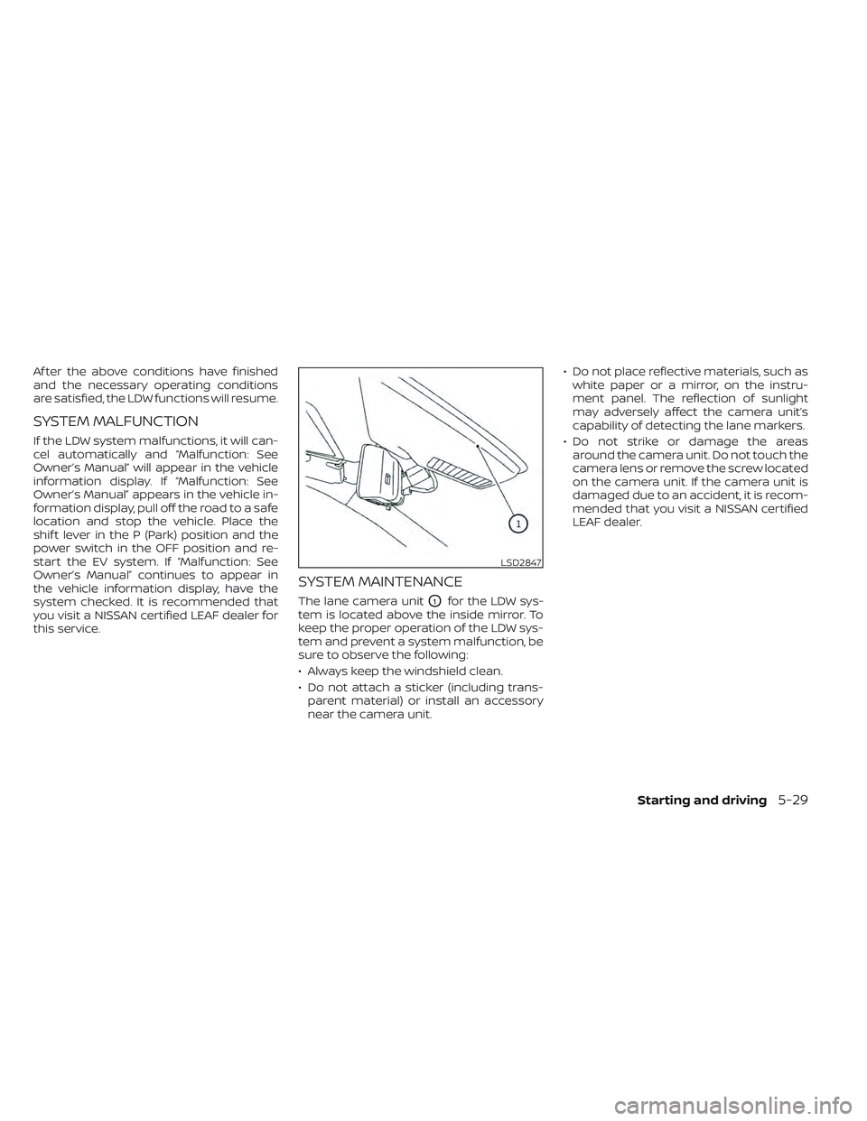
SYSTEM MAINTENANCE
The lane camera unitO1for the LDW sys-
tem is located above the inside mirror. To
keep the proper operation of the LDW sys-
tem and prevent a system malfunction, be
sure to observe the following:
• Always keep the windshield clean.
• Do not attach a sticker (including trans- parent material) or install an accessory
near the camera unit. • Do not place reflective materials, such as
white paper or a mirror, on the instru-
ment panel. The reflection of sunlight
may adversely affect the camera unit’s
capability of detecting the lane markers.
• Do not strike or damage the areas around the camera unit. Do not touch the
camera lens or remove the screw located
on the camera unit. If the camera unit is
damaged due to an accident, it is recom-
mended that you visit a NISSAN certified
LEAF dealer.
LSD2847
Starting and driving5-29
Page 355 of 618
WARNING
Failure to follow the warnings and in-
structions for proper use of the I-LI sys-
tem could result in serious injury or
death.
• The I-LI system will not steer the ve-
hicle or prevent loss of control. It is
the driver’s responsibility to stay
alert, drive safely, keep the vehicle in
the traveling lane, and be in control of
the vehicle at all times. •
The I-LI system is primarily intended
for use on well-developed freeways
or highways. It may not detect the
lane markers in certain road,
weather, or driving conditions.
The I-LI system must be turned on with the
ProPILOT Assist switch on the steering
wheel (models with ProPILOT Assist) or the
dynamic driver assistance switch (models
without ProPILOT Assist) every time the
power switch is placed in the ON position.
The I-LI system will operate when the ve-
hicle is driven at speeds of approximately
37 mph (60 km/h) and above, and only
when the lane markings are clearly visible
on the road.
The I-LI system warns the driver when the
vehicle has lef t the center of the traveling
lane with an indicator in the vehicle infor-
mation display and a steering vibration.
The system helps assist the driver to return
the vehicle to the center of the traveling
lane by applying the brakes to the lef t or
right wheels individually (for a short period
of time).
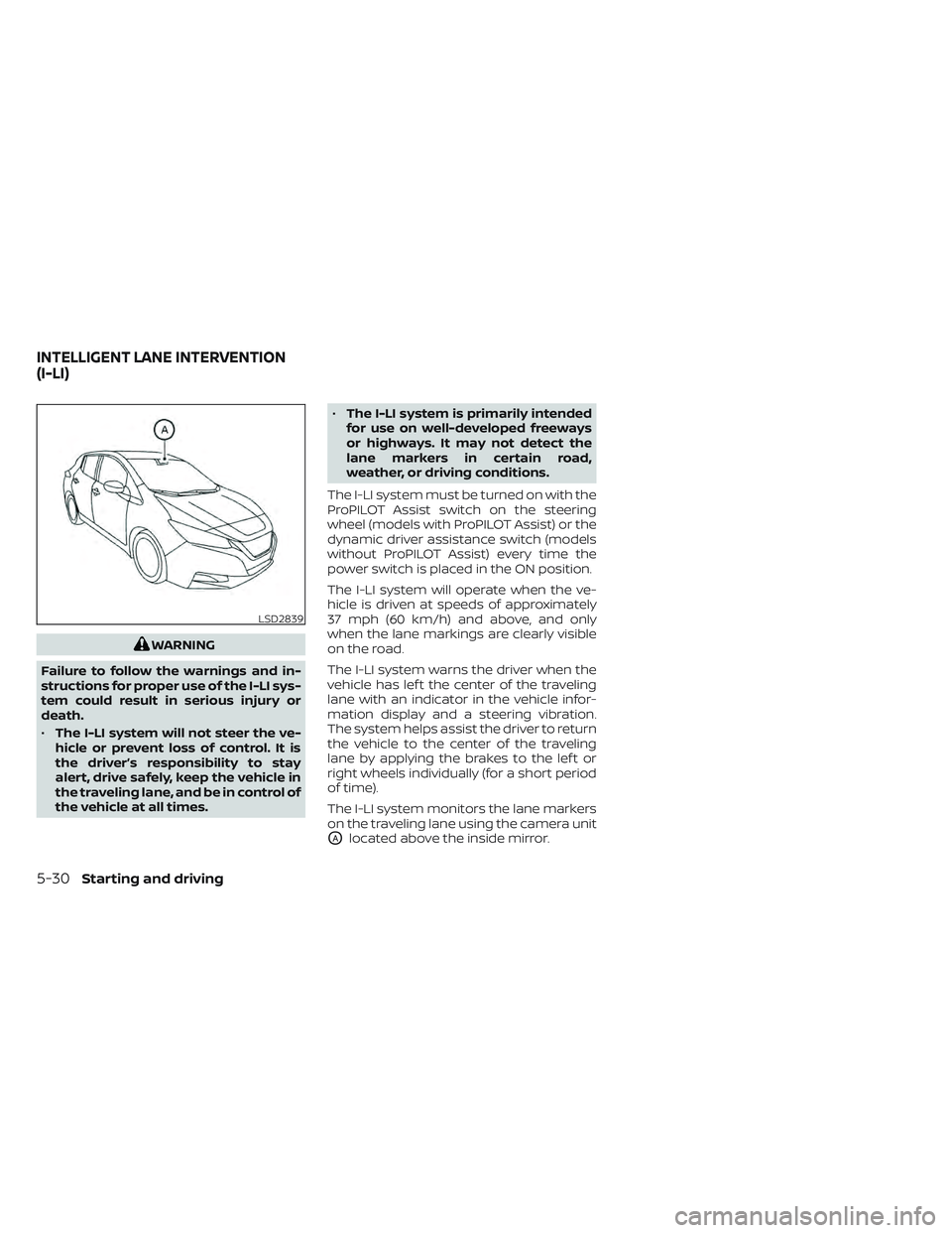
The I-LI system monitors the lane markers
on the traveling lane using the camera unit
OAlocated above the inside mirror.
LSD2839
INTELLIGENT LANE INTERVENTION
(I-LI)
5-30Starting and driving
Page 360 of 618
![NISSAN LEAF 2022 Owner´s Manual Temporary disabled status at high
temperature:
If the vehicle is parked in direct sunlight
under high temperature conditions (over
approximately 104°F [40°C]) and then the
I-LI system is turned on, NISSAN LEAF 2022 Owner´s Manual Temporary disabled status at high
temperature:
If the vehicle is parked in direct sunlight
under high temperature conditions (over
approximately 104°F [40°C]) and then the
I-LI system is turned on,](/img/5/40303/w960_40303-359.png)
Temporary disabled status at high
temperature:
If the vehicle is parked in direct sunlight
under high temperature conditions (over
approximately 104°F [40°C]) and then the
I-LI system is turned on, the I-LI system
may be deactivated automatically and the
following message will appear on the ve-
hicle information display: “Unavailable: High
Cabin Temperature.” When the interior
temperature is reduced, the system will re-
sume operating automatically.
SYSTEM MALFUNCTION
If the I-LI system malfunctions, it will cancel
automatically. The I-LI indicator (orange)
will illuminate and “Malfunction: See Own-
er’s Manual” warning message will appear
in the display.
If the I-LI indicator (orange) illuminates in
the display, pull off the road to a safe loca-
tion and stop the vehicle. Turn the EV sys-
tem off and restart the EV system. If the I-LI
indicator (orange) continues to illuminate,
have the I-LI system checked. It is recom-
mended that you visit a NISSAN certified
LEAF dealer for this service.
SYSTEM MAINTENANCE
The lane camera unitO1for the I-LI system
is located above the inside mirror. To keep
the proper operation of the I-LI system and
prevent a system malfunction, be sure to
observe the following:
• Always keep the windshield clean.
• Do not attach a sticker (including trans- parent material) or install an accessory
near the camera unit. • Do not place reflective materials, such as
white paper or a mirror, on the instru-
ment panel. The reflection of sunlight
may adversely affect the camera unit’s
capability of detecting the lane markers.
• Do not strike or damage the areas around the camera unit. Do not touch the
camera lens or remove the screw located
on the camera unit. If the camera unit is
damaged due to an accident, it is recom-
mended that you visit a NISSAN certified
LEAF dealer.
LSD2847
Starting and driving5-35
Page 361 of 618
WARNING
Failure to follow the warnings and in-
structions for proper use of the BSW
system could result in serious injury or
death.
• The BSW system is not a replacement
for proper driving procedures and is
not designed to prevent contact with
vehicles or objects. When changing
lanes, always use the side and rear
mirrors and turn and look in the di-
rection your vehicle will move to en-
sure it is safe to change lanes. Never
rely solely on the BSW system.
The BSW system helps alert the driver of
other vehicles in adjacent lanes when
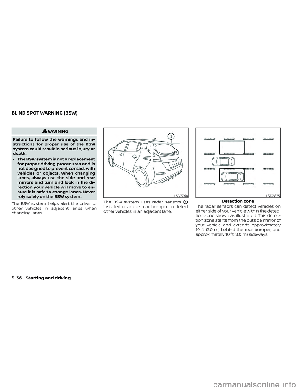
changing lanes. The BSW system uses radar sensors
O1
installed near the rear bumper to detect
other vehicles in an adjacent lane.
The radar sensors can detect vehicles on
either side of your vehicle within the detec-
tion zone shown as illustrated. This detec-
tion zone starts from the outside mirror of
your vehicle and extends approximately
10 f t (3.0 m) behind the rear bumper, and
approximately 10 f t (3.0 m) sideways.
LSD3768LSD2875
Detection zone
BLIND SPOT WARNING (BSW)
5-36Starting and driving
Page 370 of 618
For Canada
Applicable law: Canada 310
This device complies with Industry
Canada licence-exempt RSS standard(s).
Operation is subject to the following two
conditions: (1) This device may not cause
interference, and (2) This device must ac-
cept any interference, including interfer-
ence that may cause undesired opera-
tion of the device.
Frequency bands: 24.05–24.25GHz
Output power: less than 20 milliwatts
Radio frequency statement
(Type B) (if so equipped)
For USA
FCC : OAYSRR3B
This device complies with part 15 of the
FCC Rules. Operation is subject to the fol-
lowing two conditions:
(1) This device may not cause harmful
interference, and (2) this device must ac-
cept any interference received, including
interference that may cause undesired
operation.FCC Warning
Changes or modifications not expressly
approved by the party responsible for
compliance could void the user’s author-
ity to operate the equipment.
For Canada
Applicable law: Canada 310
This device contains licence-exempt
transmitter(s)/receiver(s) that comply
with Innovation, Science and Economic
Development Canada’s licence-exempt
RSS(s). Operation is subject to the fol-
lowing two conditions:
1. This device may not cause
interference.
2. This device must accept any interfer-
ence, including interference that may
cause undesired operation of the device.
Radiofrequency radiation exposure in-
formation: This equipment complies
with radiation exposure limits set forth
for an uncontrolled environment. This
equipment should be installed and oper-
ated with minimum distance of 20 cm
between the radiator and your body.
WARNING
Failure to follow the warnings and in-
structions for proper use of the I-BSI
system could result in serious injury or
death.
• The I-BSI system is not a replace-
ment for proper driving procedure
and is not designed to prevent con-
tact with vehicles or objects. When
changing lanes, always use the side
and rear mirrors and turn and look in
the direction you will move to ensure
it is safe to change lanes. Never rely
solely on the I-BSI system.
• There is a limitation to the detection
capability of the radar or the sonar.
Not every moving object or vehicle
will be detected. Using the I-BSI sys-
tem under some road, ground, lane
marker, traffic or weather conditions
could lead to improper system op-
eration. Always rely on your own op-
eration to avoid accidents.
The I-BSI system helps alert the driver of
other vehicles in adjacent lanes when
changing lanes, and helps assist the driver
to return the vehicle to the center of the
traveling lane.
INTELLIGENT BLIND SPOT
INTERVENTION (I-BSI)
Starting and driving5-45