case NISSAN MAXIMA 2000 A33 / 5.G Owners Manual
[x] Cancel search | Manufacturer: NISSAN, Model Year: 2000, Model line: MAXIMA, Model: NISSAN MAXIMA 2000 A33 / 5.GPages: 239, PDF Size: 1.97 MB
Page 5 of 239

Table of
Contents
Seats, restraints and supplemental air bag systemsInstruments and controlsPre-driving checks and adjustmentsHeater, air conditioner and audio systemsStarting and drivingIn case of emergencyAppearance and careDo-it-yourselfMaintenanceTechnical and consumer informationIndex
Z
00.1.17/A33-D/V5.0
X
Page 23 of 239

collisions, thereby restraining seat occupants.
The pre-tensioner is encased with the seat
belt's retractor. These seat belts are used the
same as conventional seat belts.
When the pre-tensioner seat belt activates,
smoke is released and a loud noise may be
heard. The smoke is not harmful, but care
should be taken not to inhale it as it may cause
irritation and choking.
If any abnormality occurs in the pre-tensioner
system, the supplemental air bag warning light
will not come on, will flash intermittently
or will turn on for 7 seconds and remain on
after the ignition key has been turned to the
ON or START position. In this case, the pre-
tensioner seat belt may not function properly.
When selling your vehicle, we request that you
inform the buyer about the pre-tensioner seat
belt system and guide the buyer to the appro-
priate sections in this Owner's Manual.
SUPPLEMENTAL AIR BAG
WARNING LABELSWarning labels about the supplemental air bag
system are placed in the vehicle as shown in
the illustration.
SPA0945A
1-18
Seats, restraints and supplemental air bag systems
Z
00.1.17/A33-D/V5.0
X
Page 34 of 239

mended practice J1819 for child restraint
installation.
Iif the child restraint is compatible with your
vehicle, place your child in the child re-
straint and check the various adjustments
to be sure the child restraint is compatible
with your child. Always follow all recom-
mended procedures.
All US states and Canadian provinces re-
quire that infants and small children be
restrained in approved child restraints at
all times while the vehicle is being oper-
ated.
WARNING
IImproper use of a child restraint can
result in increased injuries for both
the infant or child and other occu-
pants in the vehicle.
IFollow all of the child restraint manu-
facturer's instructions for installation
and use. When purchasing a child
restraint, be sure to select one which
will fit your child and vehicle. It may
not be possible to properly installsome types of child restraints in your
vehicle.
IIf the child restraint is not anchored
properly, the risk of a child being
injured in a collision or a sudden stop
greatly increases.
IAdjustable seatbacks should be posi-
tioned to fit the child restraint, but as
upright as possible.
IAfter attaching the child restraint,
test it before you place the child in it.
Tilt it from side to side. Try to tug it
forward and check to see if the belt
holds the restraint in place. If the
restraint is not secure, tighten the
belt as necessary, or put the restraint
in another seat and test it again.
IFor a front facing child restraint,
check to make sure the shoulder belt
does not go in front of the child's face
or neck. If it does, put the shoulder
belt behind the child restraint. If you
must install a front facing child re-
straint in the front seat, see instruc-
tions later in this section.IWhen your child restraint is not in
use, store it in the trunk or keep it
secured with a seat belt to prevent it
from being thrown around in case of
a sudden stop or accident.
CAUTION
Remember that a child restraint left in a
closed vehicle can become very hot.
Check the seating surface and buckles
before placing your child in the child
restraint.
Seats, restraints and supplemental air bag systems
1-29
Z
00.1.17/A33-D/V5.0
X
Page 45 of 239

2 Instruments and controlsInstrument panel ....................................................... 2-2
Meters and gauges ................................................... 2-3
Speedometer and odometer ..................................... 2-4
Tachometer ............................................................... 2-4
Engine coolant temperature gauge ........................... 2-5
Fuel gauge ................................................................ 2-5
Warning/indicator lights and chimes ......................... 2-7
Checking bulbs.......................................................... 2-7
Warning lights ........................................................... 2-7
Indicator lights ........................................................... 2-9
Chimes .................................................................... 2-11
Security systems ..................................................... 2-12
Theft warning (if so equipped) ................................ 2-12
Nissan Vehicle Immobilizer System ....................... 2-13
Windshield wiper and washer switch ...................... 2-15
Rear window and outside mirror (if so equipped)
defogger switch ....................................................... 2-16
Headlight and turn signal switch ............................. 2-17
Headlight switch ...................................................... 2-17
Turn signal switch ................................................... 2-19
Fog light switch (if so equipped) ............................. 2-19
Hazard warning flasher switch ................................ 2-20
Horn......................................................................... 2-20
Heated seats (if so equipped) ................................. 2-21Traction control system (TCS) cancel switch
(if so equipped) ....................................................... 2-22
Power outlet ............................................................ 2-22
Cigarette lighter and ashtray (accessory) ............... 2-23
Storage .................................................................... 2-23
Trays ....................................................................... 2-23
Glasses case........................................................... 2-24
Cup holder............................................................... 2-24
Glove box ................................................................ 2-25
Console box ............................................................ 2-26
Luggage net (if so equipped) .................................. 2-26
Windows .................................................................. 2-27
Power windows ....................................................... 2-27
Sunroof (if so equipped) ......................................... 2-29
Automatic sunroof ................................................... 2-29
Clock ....................................................................... 2-30
Adjusting the time ................................................... 2-30
Interior light ............................................................. 2-30
Ceiling ..................................................................... 2-30
Personal light .......................................................... 2-31
Vanity mirror light (if so equipped) .......................... 2-32
Trunk light ............................................................... 2-33
Integrated HomeLink
Universal Transceiver
(if so equipped) ....................................................... 2-33
Z
00.1.17/A33-D/V5.0
X
Page 50 of 239

ENGINE COOLANT
TEMPERATURE GAUGEThe gauge indicates the engine coolant tem-
perature.
The engine coolant temperature will vary with
the outside air temperature and driving condi-
tions.
CAUTION
If the gauge indicates engine coolant
temperature over the normal range, stop
the vehicle as soon as safely possible. If
the engine is overheated, continued op-
eration of the vehicle may seriously
damage the engine. See ªIf your vehicle
overheatsº in the ª6. In case of emer-
gencyº section for immediate action re-
quired.
FUEL GAUGEThe gauge indicates the approximate fuel level
in the tank.
The gauge may move slightly during braking,
turning, acceleration, or going up or down hill.
The gauge needle is designed to move to the
E (Empty) position when the ignition key is
turned to the OFF position.
Refill the fuel tank before the gauge regis-
ters Empty.
SIC0173
SIC0879
Instruments and controls
2-5
Z
00.1.17/A33-D/V5.0
X
Page 69 of 239

GLASSES CASEThe glasses case can be opened by pushing
the button.
WARNING
The glasses case should not be used
while driving so full attention may be
given to vehicle operation.
CAUTION
IDo not use for anything other than
glasses.
IDo not leave glasses in the glasses
case while parking in direct sunlight.
The heat may damage the glasses.
CUP HOLDER
WARNING
The cup holder should not be used while
driving so full attention may be given to
vehicle operation.
For larger cups, remove the inside tray.
SIC1238
SIC1279A
2-24
Instruments and controls
Z
00.1.17/A33-D/V5.0
X
Page 88 of 239

controller forlonger than 0.5 seconds.
2. The theft warning alarm and headlights will
stay on for 30 seconds.
3. The panic alarm stops when:
IIt has run for 30 seconds, or
IThe LOCK or the UNLOCK button is
pressed, or
IThe panic button is pushed on the multi-
remote controller for longer than 0.5 sec-
onds.
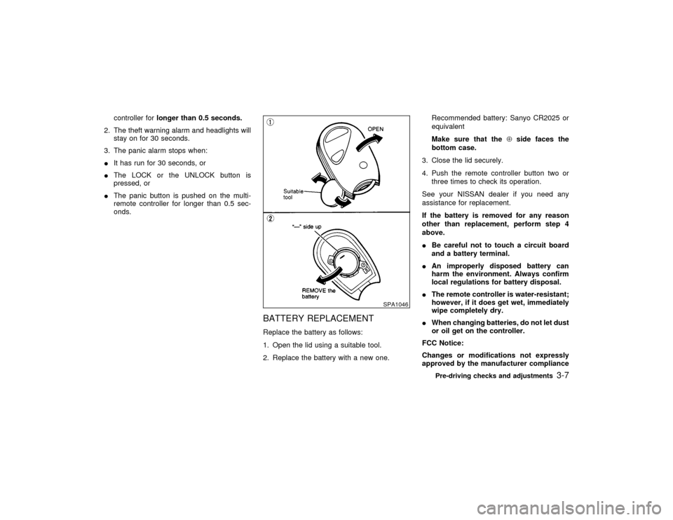
BATTERY REPLACEMENTReplace the battery as follows:
1. Open the lid using a suitable tool.
2. Replace the battery with a new one.Recommended battery: Sanyo CR2025 or
equivalent
Make sure that theÅside faces the
bottom case.
3. Close the lid securely.
4. Push the remote controller button two or
three times to check its operation.
See your NISSAN dealer if you need any
assistance for replacement.
If the battery is removed for any reason
other than replacement, perform step 4
above.
IBe careful not to touch a circuit board
and a battery terminal.
IAn improperly disposed battery can
harm the environment. Always confirm
local regulations for battery disposal.
IThe remote controller is water-resistant;
however, if it does get wet, immediately
wipe completely dry.
IWhen changing batteries, do not let dust
or oil get on the controller.
FCC Notice:
Changes or modifications not expressly
approved by the manufacturer compliance
SPA1046
Pre-driving checks and adjustments
3-7
Z
00.1.17/A33-D/V5.0
X
Page 101 of 239

fog the windshield, and the air recirculate
mode will automatically be turned off.
Outside air is drawn into the passenger com-
partment to improve the defogging perfor-
mance.Operating tipsIKeep the windows and sun roof closed
while the air conditioner is in operation.
IAfter parking in the sun, drive for 2 or 3
minutes with the windows open to vent hot
air from the passenger compartment. Then,
close the windows. This will allow the air
conditioner to cool the interior more quickly.
IThe air conditioning system should be
operated for about 10 minutes at least
once a month. This helps prevent dam-
age to the system due to lack of lubrica-
tion.
IIf the coolant temperature gauge exceeds
the HOT position, turn the air conditioning
off. For additional information, see ªIf your
vehicle overheatsº in the ª6. In case of
emergencyº section.AIR FLOW CHARTSThe charts on the following pages show the
button and lever positions formaximum andquickheating, cooling or defrosting.
The air recirculation button should be in
the OFF position for normal cooling, heat-
ing and defrosting.4-6
Heater, air conditioner and audio systems
Z
00.1.17/A33-D/V5.0
X
Page 111 of 239

tion. Pushing the button again continues the
SEEK function. Once the highest broadcasting
station is reached, the radio continues in the
SEEK mode at the lowest broadcast station.
Push the SEEK/SCAN tuning button
or
for more than 1.5 seconds. SCAN illu-
minates in the display window. SCAN tuning
begins from high to low or low to high frequen-
cies and stops at each broadcasting station for
5 seconds. Pushing the button again during
this 5 second period stops SCAN tuning and
the radio remains tuned to that station.Station memory operations:
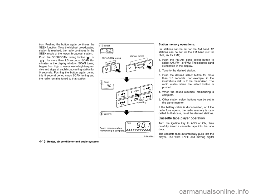
Six stations can be set for the AM band. 12
stations can be set for the FM band (six for
FM1, six for FM2).
1. Push the FM-AM band select button to
select AM, FM1, or FM2. The selected band
illuminates in the display.
2. Tune to the desired station.
3. Push the desired select button for more
than 1.5 seconds. For example, in the
illustrations ch2 is to be memorized. The
radio mutes when the select button is
pushed.
4. When the sound resumes, memorizing is
complete.
5. Other station select buttons can be set in
the same manner.
If the battery cable is disconnected, or if the
radio fuse opens, the radio memory is can-
celled. In that case, reset the desired stations.
Cassette tape player operationTurn the ignition key to ACC or ON, then
carefully insert a cassette tape into the tape
door.
The cassette tape automatically pulls into the
player. The word TAPE and moving digital
SAA0264
4-16
Heater, air conditioner and audio systems
Z
00.1.17/A33-D/V5.0
X
Page 112 of 239

squares illuminate on the right side of the
display window.
CAUTION
Do not force the cassette tape into the
tape door. This could cause player dam-
age.
The cassette tape automatically changes di-
rections to play the other side when the first
side is complete. At this time, the moving
digital squares illuminate on the left side of the
display window.
Precaution on cassette player operation:
ITo maintain good quality sound,
NISSAN recommends using cassette
tapes of 60 minutes or shorter in length.
ICassette tapes should be removed from
the player when not in use. Store cas-
settes in their protective cases and away
from direct sunlight, heat, dust, mois-
ture and magnetic sources.
IDirect sunlight can cause the cassette to
become deformed. The use of deformed
cassettes may cause the cassette to jam
in the player.IDo not use cassettes with labels which
are peeling and loose. If used, the label
could jam in the player.
IIf a cassette has loose tape, insert a
pencil through one of the cassette hubs
and rewind the tape firmly around the
hubs. Loose tape may cause tape jam-
ming and wavering sound quality.
IOver a period of time, the playback
head, capstan and pinch roller may col-
lect a tape coating residue as the tape is
played. This residue accumulation can
cause weak or wavering sound, and
should be removed periodically with a
head cleaning tape. If the residue is not
removed periodically, the player may
need to be disassembled for cleaning.
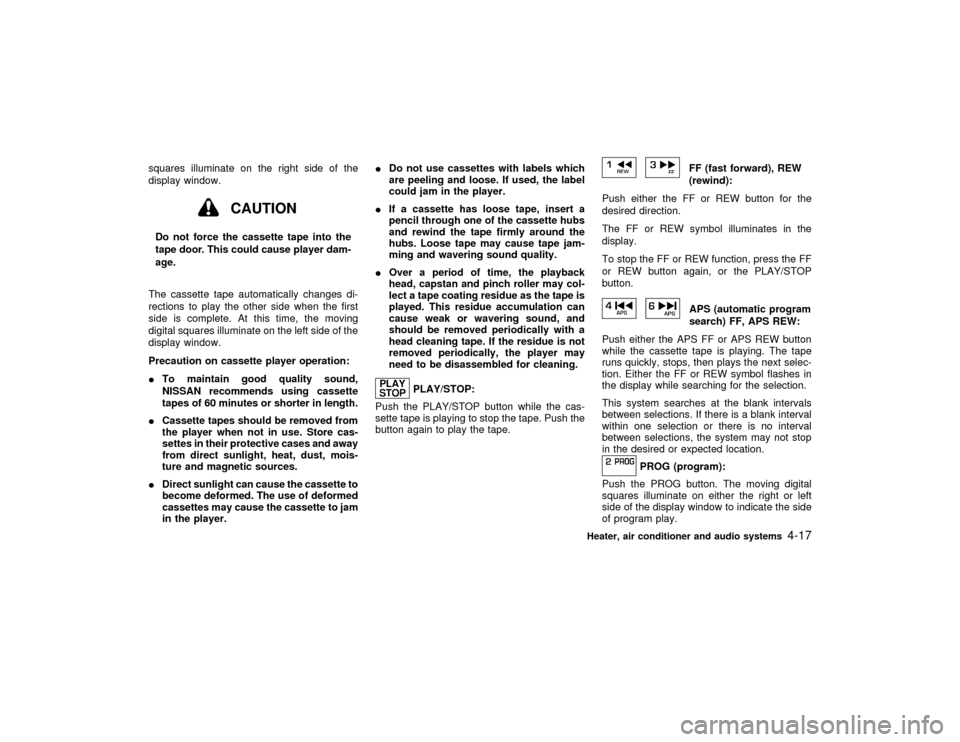
PLAY/STOP:
Push the PLAY/STOP button while the cas-
sette tape is playing to stop the tape. Push the
button again to play the tape.
FF (fast forward), REW
(rewind):
Push either the FF or REW button for the
desired direction.
The FF or REW symbol illuminates in the
display.
To stop the FF or REW function, press the FF
or REW button again, or the PLAY/STOP
button.APS (automatic program
search) FF, APS REW:
Push either the APS FF or APS REW button
while the cassette tape is playing. The tape
runs quickly, stops, then plays the next selec-
tion. Either the FF or REW symbol flashes in
the display while searching for the selection.
This system searches at the blank intervals
between selections. If there is a blank interval
within one selection or there is no interval
between selections, the system may not stop
in the desired or expected location.
PROG (program):
Push the PROG button. The moving digital
squares illuminate on either the right or left
side of the display window to indicate the side
of program play.
Heater, air conditioner and audio systems
4-17
Z
00.1.17/A33-D/V5.0
X