warning light NISSAN MAXIMA 2004 A34 / 6.G Service Manual
[x] Cancel search | Manufacturer: NISSAN, Model Year: 2004, Model line: MAXIMA, Model: NISSAN MAXIMA 2004 A34 / 6.GPages: 280, PDF Size: 3.99 MB
Page 181 of 280

ing abruptly or when braking on a slippery road.
Thus, difficult steering and swerving of the ve-
hicle due to locked wheels is minimized. The
system detects the wheel rotation rate and elec-
tronically controls the pressure applied to each
brake. Slight vibration on the brake pedal accom-
panied by noise usually occurs while the ABS
system is operating. Such vibration and noise
encountered during abrupt braking is not a prob-
lem, but indicates that the system is functioning
properly. However, the pulsation may indicate
that road conditions are hazardous and extra care
is required while driving.
Self-test feature
The anti-lock brake system consists of electronic
sensors and hydraulic solenoids controlled by a
computer. The computer has a built-in diagnostic
feature that tests the system each time you start
the engine and move the vehicle at a low speed in
forward or reverse. When the self-test occurs,
you may hear a ‘‘clunk’’ noise and/or feel a pulsa-
tion in the brake pedal. This is normal and is not
an indication of any malfunction. If the computer
senses any malfunction, it switches the anti-lock
brake system off and turns on the ABS brake
warning light on the instrument panel. The brake
system then operates normally, but without anti-
lock assistance.If a malfunction occurs in the system, the anti-
lock function will not operate, but the standard
vehicle brake system will continue to operate
normally. The ABS brake warning light will then
come on.
If the light comes on during the self-test or while
driving, take the vehicle to a NISSAN dealer for
repair.
WARNING
cThe anti-lock brake system is a sophis-
ticated device, but it cannot prevent ac-
cidents resulting from careless or dan-
gerous driving techniques. It can help
maintain vehicle control during braking
on slippery surfaces, but remember that
the stopping distance on slippery sur-
faces will be longer than on normal
surfaces even with the anti-lock brake
system. Stopping distances may also
be longer on rough, gravel or snow cov-
ered roads, or if you are using tire
chains. Tire type and condition may also
affect braking effectiveness. Always
maintain a safe distance from the ve-
hicle in front of you. Ultimately, the re-
sponsibility for safety of self and others
rests in the hands of the driver.cTire type and condition of tires may also
affect braking effectiveness.
cWhen replacing tires, install the speci-
fied size of tires on all four wheels.
cWhen installing a spare tire, make sure
it is the proper size and type as speci-
fied on the tire placard. For tire placard
location information, refer to “Tire plac-
ard” in the “Technical and consumer
information” section of this manual.
cRefer to “Wheels and tires” in the
“Maintenance and do-it-yourself” sec-
tion of this manual.
Starting and driving5-19
ZREVIEW COPY:Ð2004 Maxima(max)
Owners Manual(owners)ÐUSA English(nna)
10/07/03Ðtbrooks
X
Page 182 of 280

When accelerating on slippery surfaces the tire
may spin or slip. With the vehicle traction control
system, sensors detect these movements and
control the braking and engine output to help
improve vehicle stability while accelerating.
cWhen the traction control system is operat-
ing, the slip indicator in the instrument panel
blinks.
cIf the slip indicator blinks, the vehicle is un-
der slippery conditions. Be sure to drive
carefully. See “Slip indicator light” and “Trac-
tion control off indicator light” in the “Instru-
ments and controls” section of this manual.
cIf a malfunction occurs in the system,
the
andindicator lights
come on in the meter panel.
As long as these warning lights are on, the trac-
tion control function is canceled. The vehicle will
behave like a vehicle without the system.
WARNING
cThe traction control system is designed
to help improve driving stability but
does not prevent accidents due to
abrupt steering operation at high
speeds or by careless or dangerous
driving techniques. Reduce vehicle
speed and be especially careful when
driving and cornering on slippery sur-
faces and always drive carefully.
cIf brake related parts such as brake
pads, rotors and calipers are not stan-
dard equipment or are extremely dete-
riorated, the traction control system
may not operate properly and the
indicator light may come on.
cDo not modify the vehicle’s suspension.
If suspension parts such as shock ab-
sorbers, struts, springs and bushings
are not standard equipment or are ex-
tremely deteriorated, the traction con-
trol system may not operate properly
and the
indicator light may come
on.cWhen driving on extremely inclined sur-
faces such as higher banked corners,
the traction control system may not op-
erate properly and the
indicator
light may come on. Do not drive on
these types of roads.
cIf wheels or tires other than the recom-
mended ones are used, the traction
control system may not operate prop-
erly and the
indicator light may
come on.
cThe traction control system is not a sub-
stitute for winter tires or tire chains on a
snow covered road.
TRACTION CONTROL SYSTEM (TCS)
(if so equipped)
5-20Starting and driving
ZREVIEW COPY:Ð2004 Maxima(max)
Owners Manual(owners)ÐUSA English(nna)
10/07/03Ðtbrooks
X
Page 183 of 280

When accelerating or driving on slippery sur-
faces, the tires may spin or slide. With the Vehicle
Dynamic Control (VDC) system, sensors detect
these movements and control the braking and
engine output to help improve vehicle stability.
cWhen the vehicle dynamic control (VDC)
system is operating, the slip indicator in the
instrument panel blinks.
cWhen only the traction control system (TCS)
portion of the vehicle dynamic control sys-
tem is operating, the slip indicator will also
blink.
cIf the slip indicator blinks, the road condi-
tions are slippery. Be sure to adjust your
speed and driving to these conditions. See
“Slip indicator light”, and “Vehicle dynamic
control off indicator light” in the “Instruments
and controls” section.
cIndicator light
If malfunction occurs in the system,
the
andindicator lights come
on in the instrument panel.
As long as these warning lights are on, the
traction control function is canceled.
The VDC system uses an Active Brake Limited
Slip (ABLS) system to improve vehicle traction.
The ABLS system works when one of the driving
wheels is spinning on a slippery surface. TheABLS system brakes the spinning wheel which
distributes the driving power to the other drive
wheel. If the vehicle is operated with the vehicle
dynamic control system off, all VDC and TCS
functions will be turned off. The ABLS system
and ABS will still operate with the VDC system
OFF. If the ABLS system or the ABS is activated,
the slip indicator light will blink and you may hear
a clunk noise and/or feel a pulsation in the brake
pedal. This is normal.
While the VDC system is operating, you may feel
a pulsation in the brake pedal and hear a noise or
vibration from under the hood. This is normal and
indicates that the VDC system is working prop-
erly.
The computer has a built in diagnostic feature
that tests the system each time you start the
engine and move the vehicle forward or in reverse
at a slow speed. When the self-test occurs, you
may hear a clunk noise and/or feel a pulsation in
the brake pedal. This is normal and is not an
indication of a malfunction.
WARNING
cThe vehicle dynamic control system is
designed to help improve driving stabil-
ity but does not prevent accidents due
to abrupt steering operation at high
speeds or by careless or dangerous
driving techniques. Reduce vehicle
speed and be especially careful when
driving and cornering on slippery sur-
faces and always drive carefully.
cIf brake related parts such as brake
pads, rotors and calipers are not stan-
dard equipment or are extremely dete-
riorated, the vehicle dynamic control
system may not operate properly and
the vehicle dynamic control off indica-
tor light may come on.
cDo not modify the vehicle’s suspension.
If suspension parts such as shock ab-
sorbers, struts, springs, stabilizer bars
and bushings are not NISSAN approved
for your vehicle or are extremely dete-
riorated the vehicle dynamic control
system may not operate properly. This
could adversely affect vehicle handling
performance, and the vehicle dynamic
control off indicator light may come on.
VEHICLE DYNAMIC CONTROL (VDC)
SYSTEM (if so equipped)
Starting and driving5-21
ZREVIEW COPY:Ð2004 Maxima(max)
Owners Manual(owners)ÐUSA English(nna)
10/07/03Ðtbrooks
X
Page 193 of 280
cWhenever working on or near a battery,
always wear suitable eye protectors (for
example, goggles or industrial safety
spectacles) and remove rings, metal
bands, or any other jewelry. Do not lean
over the battery when jump starting.
cDo not attempt to jump start a frozen
battery. It could explode and cause se-
rious injury.
cYour vehicle has an automatic engine
cooling fan. It could come on at any
time. Keep hands and other objects
away from it.
WARNING
Always follow the instructions below.
Failure to do so could result in damage to
the charging system and cause personal
injury.
1. If the booster battery is in another vehicle,
position the two vehicles to bring their bat-
teries near each other.
Do not allow the two vehicles to touch.2. Apply the parking brake. Move the shift lever
to N (Neutral) (manual transmission) or to P
(Park) (automatic transmission) . Switch off
all unnecessary electrical systems (lights,
heater, air conditioner, etc.) .
3. Remove vent caps on the battery (if so
equipped) . Cover the battery with an old
cloth to reduce explosion hazard.
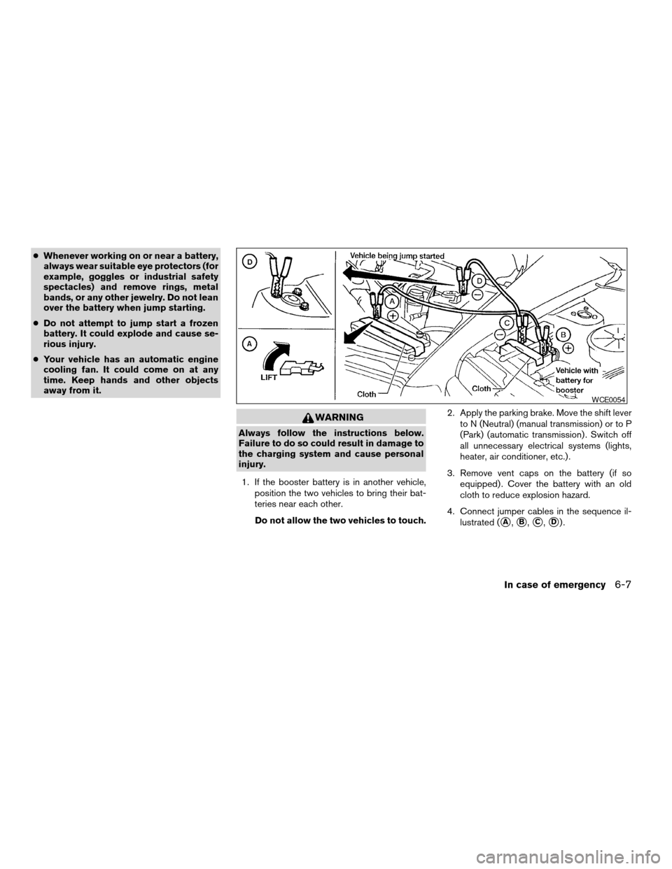
4. Connect jumper cables in the sequence il-
lustrated (
sA,sB,sC,sD).
WCE0054
In case of emergency6-7
ZREVIEW COPY:Ð2004 Maxima(max)
Owners Manual(owners)ÐUSA English(nna)
10/21/03Ðbetty
X
Page 207 of 280
When driving in areas using road salt or other
corrosive materials, check lubrication frequently.
Lights*Clean the headlights on a regular basis.
Make sure that the headlights, stop lights, tail
lights, turn signal lights, and other lights are all
operating properly and installed securely. Also
check headlight aim.
Road wheel nuts*When checking the tires,
make sure no wheel nuts are missing, and check
for any loose wheel nuts. Tighten if necessary.
Tire rotation*Tires should be rotated every
7,500 miles (12,000 km) .
Tires*Check the pressure with a gauge often
and always prior to long distance trips. If neces-
sary, adjust the pressure in all tires, including the
spare, to the pressure specified. Check carefully
for damage, cuts or excessive wear.
Wheel alignment and balanceIf the vehicle
should pull to either side while driving on a
straight and level road, or if you detect uneven or
abnormal tire wear, there may be a need for wheel
alignment. If the steering wheel or seat vibrates at
normal highway speeds, wheel balancing may be
needed.
cFor additional information regarding tires,
refer to “Important Tire Safety Information”
(US) or “Tire Safety Information” (Canada) in
the Warranty Information Booklet .WindshieldClean the windshield on a regular
basis. Check the windshield at least every six
months for cracks or other damage. Have a dam-
aged windshield repaired by a qualified repair
facility.
Windshield wiper blades*Check for cracks or
wear if they do not wipe properly.
Inside the vehicle
The maintenance items listed here should be
checked on a regular basis, such as when per-
forming periodic maintenance, cleaning the ve-
hicle, etc.
Additional information on the following
items with an “*” is found later in this sec-
tion.
Accelerator pedalCheck the pedal for smooth
operation and make sure the pedal does not bind
or require uneven effort. Keep the floor mat away
from the pedal.
Automatic transmission P (Park) position
mechanismOn a fairly steep hill check that your
vehicle is held securely with the selector lever in
the P position without applying any brakes.
Brake pedal and booster*Check the pedal for
smooth operation and make sure it has the proper
distance under it when depressed fully. Checkthe brake booster function. Be certain to keep the
floor mat away from the pedal.
BrakesCheck that the brakes do not pull the
vehicle to one side when applied.
Clutch pedal*Make sure the pedal operates
smoothly and check that it has the proper free
travel.
Parking brake*Check that the lever has the
proper travel and confirm that your vehicle is held
securely on a fairly steep hill with only the parking
brake applied.
SeatsCheck seat position controls such as seat
adjusters, seatback recliner, etc. to ensure they
operate smoothly and all latches lock securely in
every position. Check that the head restraints
move up and down smoothly and the locks (if so
equipped) hold securely in all latched positions.
Seat beltsCheck that all parts of the seat belt
system (for example, buckles, anchors, adjusters
and retractors) operate properly and smoothly,
and are installed securely. Check the belt web-
bing for cuts, fraying, wear or damage.
Steering wheelCheck for changes in the steer-
ing system, such as excessive freeplay, hard
steering or strange noises.
Warning lights and chimesMake sure all
warning lights and chimes are operating properly.
Maintenance and do-it-yourself8-3
ZREVIEW COPY:Ð2004 Maxima(max)
Owners Manual(owners)ÐUSA English(nna)
10/20/03Ðarosenma
X
Page 217 of 280
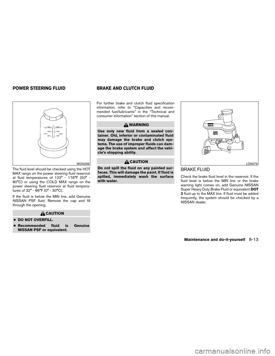
The fluid level should be checked using the HOT
MAX range on the power steering fluid reservoir
at fluid temperatures of 122° - 176°F (50° -
80°C) or using the COLD MAX range on the
power steering fluid reservoir at fluid tempera-
tures of 32° - 86°F (0° - 30°C) .
If the fluid is below the MIN line, add Genuine
NISSAN PSF fluid. Remove the cap and fill
through the opening.
CAUTION
cDO NOT OVERFILL.
cRecommended fluid is Genuine
NISSAN PSF or equivalent.For further brake and clutch fluid specification
information, refer to “Capacities and recom-
mended fuel/lubricants” in the “Technical and
consumer information” section of this manual.
WARNING
Use only new fluid from a sealed con-
tainer. Old, inferior or contaminated fluid
may damage the brake and clutch sys-
tems. The use of improper fluids can dam-
age the brake system and affect the vehi-
cle’s stopping ability.
CAUTION
Do not spill the fluid on any painted sur-
faces. This will damage the paint. If fluid is
spilled, immediately wash the surface
with water.BRAKE FLUID
Check the brake fluid level in the reservoir. If the
fluid level is below the MIN line or the brake
warning light comes on, add Genuine NISSAN
Super Heavy Duty Brake Fluid or equivalentDOT
3fluid up to the MAX line. If fluid must be added
frequently, the system should be checked by a
NISSAN dealer.
WDI0256LDI0079
POWER STEERING FLUID BRAKE AND CLUTCH FLUID
Maintenance and do-it-yourself8-13
ZREVIEW COPY:Ð2004 Maxima(max)
Owners Manual(owners)ÐUSA English(nna)
10/20/03Ðarosenma
X
Page 218 of 280
CLUTCH FLUID
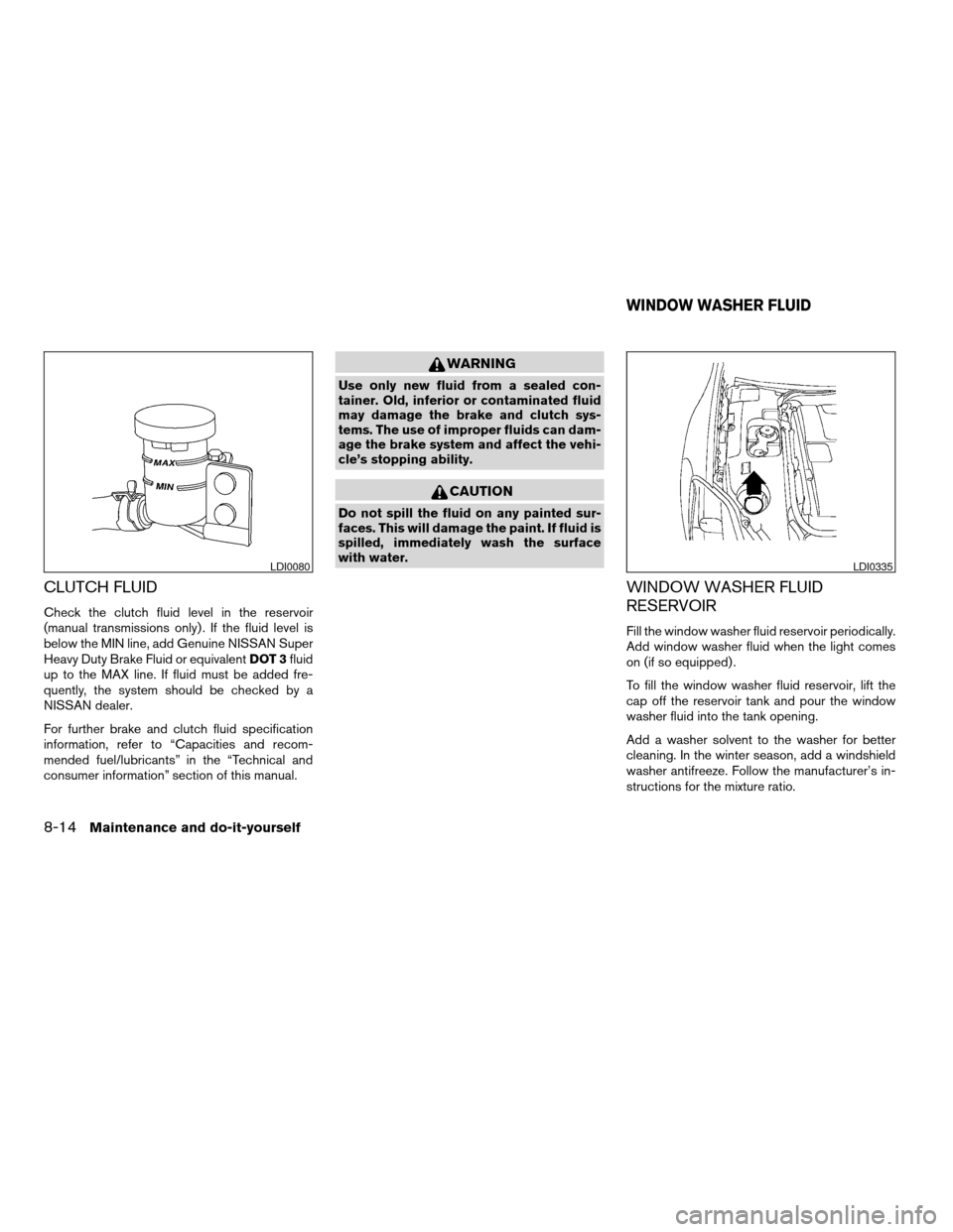
Check the clutch fluid level in the reservoir
(manual transmissions only) . If the fluid level is
below the MIN line, add Genuine NISSAN Super
Heavy Duty Brake Fluid or equivalentDOT 3fluid
up to the MAX line. If fluid must be added fre-
quently, the system should be checked by a
NISSAN dealer.
For further brake and clutch fluid specification
information, refer to “Capacities and recom-
mended fuel/lubricants” in the “Technical and
consumer information” section of this manual.
WARNING
Use only new fluid from a sealed con-
tainer. Old, inferior or contaminated fluid
may damage the brake and clutch sys-
tems. The use of improper fluids can dam-
age the brake system and affect the vehi-
cle’s stopping ability.
CAUTION
Do not spill the fluid on any painted sur-
faces. This will damage the paint. If fluid is
spilled, immediately wash the surface
with water.
WINDOW WASHER FLUID
RESERVOIR
Fill the window washer fluid reservoir periodically.
Add window washer fluid when the light comes
on (if so equipped) .
To fill the window washer fluid reservoir, lift the
cap off the reservoir tank and pour the window
washer fluid into the tank opening.
Add a washer solvent to the washer for better
cleaning. In the winter season, add a windshield
washer antifreeze. Follow the manufacturer’s in-
structions for the mixture ratio.
LDI0080LDI0335
WINDOW WASHER FLUID
8-14Maintenance and do-it-yourself
ZREVIEW COPY:Ð2004 Maxima(max)
Owners Manual(owners)ÐUSA English(nna)
10/20/03Ðarosenma
X
Page 227 of 280
Self-adjusting brakes
Your vehicle is equipped with self-adjusting
brakes.
The front and rear disc-type brakes self-adjust
every time the brake pedal is applied.
WARNING
See a NISSAN dealer for a brake system
check if the brake pedal height does not
return to normal.
Brake pad wear indicators
The disc brake pads on your vehicle have audible
wear indicators. When a brake pad requires re-
placement, a high pitched scraping or screech-
ing sound will be heard when the vehicle is in
motion. The noise will be heard whether or not the
brake pedal is depressed. Have the brakes
checked as soon as possible if the wear indicator
sound is heard.
Under some driving or climate conditions, occa-
sional brake squeak, squeal or other noise may
be heard. Occasional brake noise during light to
moderate stops is normal and does not affect the
function or performance of the brake system.
Proper brake inspection intervals should
be followed.For more information regarding
brake inspections, see the appropriate mainte-nance schedule information in the “NISSAN Ser-
vice and Maintenance Guide”.
BRAKE BOOSTER
Check the brake booster function as follows:
1. With the engine off, press and release the
brake pedal several times. When brake
pedal movement (distance of travel) remains
the same from one pedal application to the
next, continue on to the next step.
2. While depressing the brake pedal, start the
engine. The pedal height should drop a little.
3. With the brake pedal depressed, stop the
engine. Keep the pedal depressed for about
30 seconds. The pedal height should not
change.
4. Run the engine for one minute without de-
pressing the brake pedal, then turn it off.
Depress the brake pedal several times. The
pedal travel distance will decrease gradually
with each depression as the vacuum is re-
leased from the booster.
If the brakes do not operate properly, have the
brakes checked by a NISSAN dealer.
ENGINE COMPARTMENT
CAUTION
Never use a fuse of a higher or lower
amperage rating than specified on the
fuse box cover. This could damage the
electrical system or cause a fire.
If any electrical equipment does not come on,
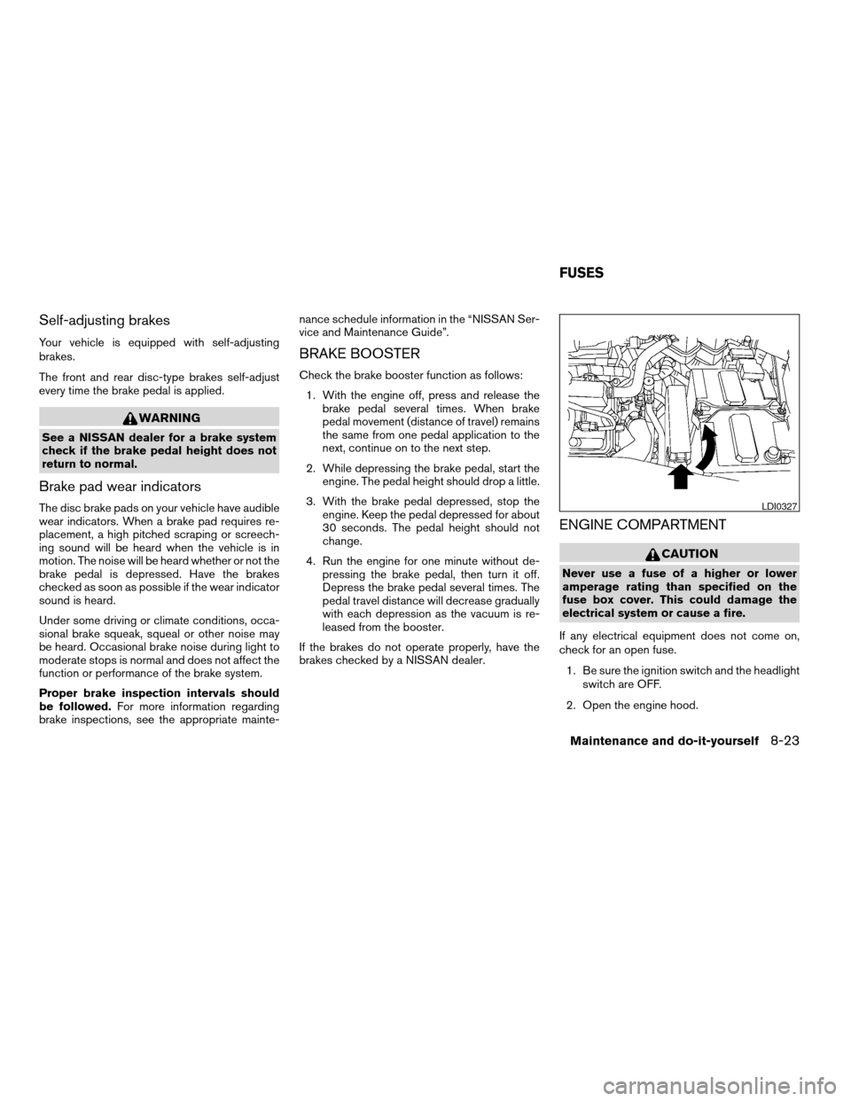
check for an open fuse.
1. Be sure the ignition switch and the headlight
switch are OFF.
2. Open the engine hood.
LDI0327
FUSES
Maintenance and do-it-yourself8-23
ZREVIEW COPY:Ð2004 Maxima(max)
Owners Manual(owners)ÐUSA English(nna)
10/20/03Ðarosenma
X
Page 231 of 280

HEADLIGHTS
Replacing the xenon headlight bulb
WARNING
cHIGH VOLTAGE
When xenon headlights are on, they pro-
duce a high voltage. To prevent an electric
shock, never attempt to modify or disas-
semble. Always have your xenon head-
lights replaced at a NISSAN dealer. For
additional information, see “Headlight
and turn signal switch” in the “Instru-
ments and controls” section.
Replacing the halogen headlight bulb
The headlight is a semi-sealed beam type which
uses a replaceable headlight (halogen) bulb. Be-
cause the headlight assembly must be removed
from the vehicle for bulb replacement, see your
NISSAN dealer.
CAUTION
cAiming is not necessary after replacing
the bulb. When aiming adjustment is
necessary, contact a NISSAN dealer.cDo not leave the headlight assembly
open without a bulb installed for a long
period of time. Dust, moisture, smoke,
etc. entering the headlight body may
affect bulb performance. Remove the
bulb from the headlight assembly just
before a replacement bulb is installed.
cOnly touch the plastic base when han-
dling the bulb. Never touch the glass
envelope. Touching the glass could sig-
nificantly affect bulb life and/or head-
light performance.
cHigh pressure halogen gas is sealed
inside the halogen bulb. The bulb may
break if the glass envelope is scratched
or the bulb is dropped.
cUse the same number and wattage as
originally installed:
Low beam:
Wattage: 55
Bulb no.: 9012*
High beam:
Wattage: 55
Bulb no.: 9012*
*: Always check with the Parts Depart-
ment at a NISSAN dealer for the latest
parts information.
LIGHTS
Maintenance and do-it-yourself8-27
ZREVIEW COPY:Ð2004 Maxima(max)
Owners Manual(owners)ÐUSA English(nna)
10/20/03Ðarosenma
X
Page 245 of 280
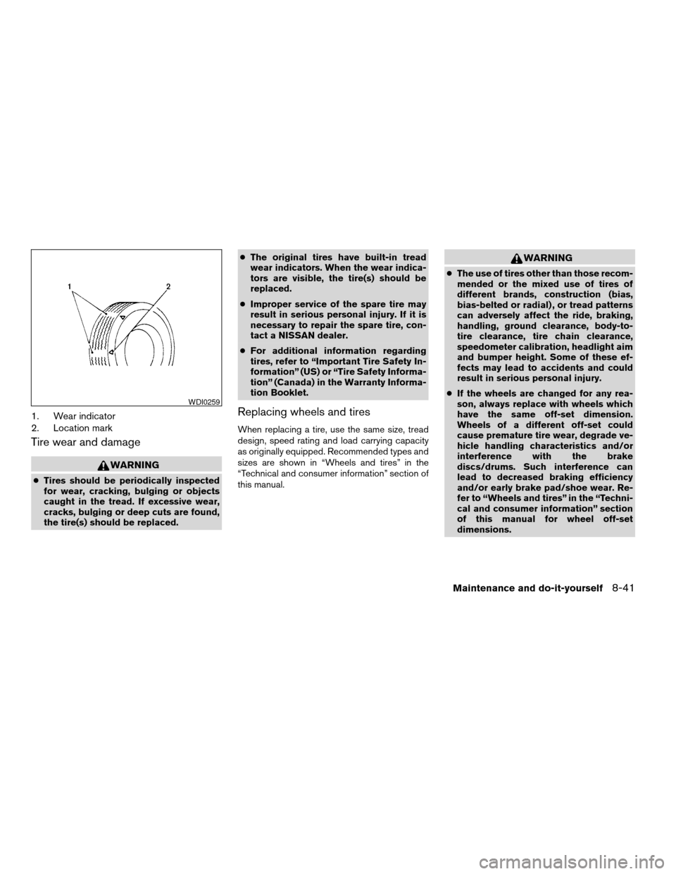
1. Wear indicator
2. Location mark
Tire wear and damage
WARNING
cTires should be periodically inspected
for wear, cracking, bulging or objects
caught in the tread. If excessive wear,
cracks, bulging or deep cuts are found,
the tire(s) should be replaced.cThe original tires have built-in tread
wear indicators. When the wear indica-
tors are visible, the tire(s) should be
replaced.
cImproper service of the spare tire may
result in serious personal injury. If it is
necessary to repair the spare tire, con-
tact a NISSAN dealer.
cFor additional information regarding
tires, refer to “Important Tire Safety In-
formation” (US) or “Tire Safety Informa-
tion” (Canada) in the Warranty Informa-
tion Booklet.
Replacing wheels and tires
When replacing a tire, use the same size, tread
design, speed rating and load carrying capacity
as originally equipped. Recommended types and
sizes are shown in “Wheels and tires” in the
“Technical and consumer information” section of
this manual.
WARNING
cThe use of tires other than those recom-
mended or the mixed use of tires of
different brands, construction (bias,
bias-belted or radial) , or tread patterns
can adversely affect the ride, braking,
handling, ground clearance, body-to-
tire clearance, tire chain clearance,
speedometer calibration, headlight aim
and bumper height. Some of these ef-
fects may lead to accidents and could
result in serious personal injury.
cIf the wheels are changed for any rea-
son, always replace with wheels which
have the same off-set dimension.
Wheels of a different off-set could
cause premature tire wear, degrade ve-
hicle handling characteristics and/or
interference with the brake
discs/drums. Such interference can
lead to decreased braking efficiency
and/or early brake pad/shoe wear. Re-
fer to “Wheels and tires” in the “Techni-
cal and consumer information” section
of this manual for wheel off-set
dimensions.
WDI0259
Maintenance and do-it-yourself8-41
ZREVIEW COPY:Ð2004 Maxima(max)
Owners Manual(owners)ÐUSA English(nna)
10/20/03Ðarosenma
X