ignition NISSAN MAXIMA 2005 A34 / 6.G Repair Manual
[x] Cancel search | Manufacturer: NISSAN, Model Year: 2005, Model line: MAXIMA, Model: NISSAN MAXIMA 2005 A34 / 6.GPages: 288, PDF Size: 4.71 MB
Page 217 of 288
When performing any inspection or maintenance
work on your vehicle, always take care to prevent
serious accidental injury to yourself or damage to
the vehicle. The following are general precau-
tions which should be closely observed.
WARNING
cPark the vehicle on a level surface, ap-
ply the parking brake securely and
block the wheels to prevent the vehicle
from moving. For manual transmission
models, move the shift lever to N (Neu-
tral) . For automatic transmission mod-
els, move the selector lever to P (Park) .
cBe sure the ignition key is in the OFF or
LOCK position when performing any
parts replacement or repairs.
cNever leave the engine or automatic
transmission related component har-
nesses disconnected while the ignition
switch is in the ON position.
cNever connect or disconnect the battery
or any transistorized component while
the ignition switch is in the ON position.
cYour vehicle is equipped with an auto-
matic engine cooling fan. It may come
on at any time without warning, even if
the ignition key is in the OFF positionand the engine is not running. To avoid
injury, always disconnect the negative
battery cable before working near the
fan.
cIf you must work with the engine run-
ning, keep your hands, clothing, hair
and tools away from moving fans, belts
and any other moving parts.
cIt is advisable to secure or remove any
loose clothing and remove any jewelry,
such as rings, watches, etc. before
working on your vehicle.
cAlways wear eye protection whenever
you work on your vehicle.
cIf you must run the engine in an en-
closed space such as a garage, be sure
there is proper ventilation for exhaust
gases to escape.
cNever get under the vehicle while it is
supported only by a jack. If it is neces-
sary to work under the vehicle, support
it with safety stands.
cKeep smoking materials, flame and
sparks away from the fuel tank and
battery.
cOn gasoline engine models with the
multiport fuel injection (MFI) system,the fuel filter or fuel lines should be
serviced by a NISSAN dealer because
the fuel lines are under high pressure
even when the engine is off.
CAUTION
cDo not work under the hood while the
engine is hot. Turn the engine off and
wait until it cools down.
cAvoid contact with used engine oil and
coolant. Improperly disposed engine
oil, engine coolant and/or other vehicle
fluids can damage the environment. Al-
ways conform to local regulations for
disposal of vehicle fluid.
This “Maintenance and do-it-yourself” section
gives instructions regarding only those items
which are relatively easy for an owner to perform.
A genuine NISSAN service manual is also avail-
able. See “Owner’s Manual/Service Manual or-
der information” in the “Technical and consumer
information” section of this manual.
You should be aware that incomplete or improper
servicing may result in operating difficulties or
excessive emissions, and could affect warranty
coverage.If in doubt about any servicing,
have it done by a NISSAN dealer.
MAINTENANCE PRECAUTIONS
Maintenance and do-it-yourself8-5
ZREVIEW COPYÐ2005 Maxima(max)
Owners ManualÐUSA_English(nna)
09/01/04Ðtbrooks
X
Page 227 of 288

1. Power steering fluid pump
2. Crankshaft
3. Generator
4. Air conditioner
WARNING
Be sure the ignition key is in the OFF or
LOCK position. The engine could rotate
unexpectedly.
1. Visually inspect each belt for signs of un-
usual wear, cuts, fraying or looseness. If the
belt is in poor condition or is loose, have it
replaced or adjusted by a NISSAN dealer.2. Have the belts checked regularly for condi-
tion and tension in accordance with the
maintenance schedule found in the
“NISSAN Service and Maintenance Guide”.
REPLACING SPARK PLUGS
Platinum-tipped spark plugs
It is not necessary to replace platinum-tipped
spark plugs as frequently as conventional type
spark plugs because they last much longer. Fol-
low the maintenance log shown in the “NISSAN
Service and Maintenance Guide”. Do not service
platinum-tipped spark plugs by cleaning or re-
gapping.
cAlways replace spark plugs with rec-
ommended or equivalent ones.
WDI0226WDI0005
DRIVE BELTSSPARK PLUGS
Maintenance and do-it-yourself8-15
ZREVIEW COPYÐ2005 Maxima(max)
Owners ManualÐUSA_English(nna)
09/01/04Ðtbrooks
X
Page 228 of 288

WARNING
Be sure the engine and ignition switch are
off and that the parking brake is engaged
securely.
CAUTION
Be sure to use the correct socket to re-
move the spark plugs. An incorrect socket
can damage the spark plugs.
If replacement is required, please see your
NISSAN dealer for assistance.
The air cleaner filter should not be cleaned and
reused. Replace it according to the maintenance
log shown in the “NISSAN Service and Mainte-
nance Guide.” When replacing the filter, wipe the
inside of the air cleaner filter housing and the
cover with a damp cloth.
To remove the air cleaner filter:
s1Loosen the screw.
s2Disconnect the electrical connector.
s3Push down on the clips and remove the air
cleaner cover. Remove the air cleaner filter.
WARNING
cOperating the engine with the air
cleaner removed can cause you or oth-
ers to be burned. The air cleaner not
only cleans the air, it stops the flame if
the engine backfires. If it isn’t there, and
the engine backfires, you could be
burned. Do not drive with the air cleaner
removed, and be careful when working
on the engine with the air cleaner
removed.
cNever pour fuel into the throttle body or
attempt to start the engine with the air
cleaner removed. Doing so could result
in serious injury.
IN-CABIN MICROFILTER
The in-cabin microfilter restricts the entry of air-
borne dust and pollen particles and reduces
some objectionable outside odors. The filter is
located behind the glove box. Refer to the
“NISSAN Service and Maintenance Guide” for
change intervals.
To replace the filter, perform the following proce-
dure:
LDI0336
AIR CLEANER
8-16Maintenance and do-it-yourself
ZREVIEW COPYÐ2005 Maxima(max)
Owners ManualÐUSA_English(nna)
09/01/04Ðtbrooks
X
Page 234 of 288

If a type A fuse is used to replace a type B fuse,
the type A fuse will not be level with the fuse
pocket as shown in the illustration. This will not
affect the performance of the fuse. Make sure the
fuse is installed in the fuse box securely.
Type B fuses cannot be installed in the under-
hood fuse boxes. Only use type A fuses in the
underhood fuse boxes.ENGINE COMPARTMENT
CAUTION
Never use a fuse of a higher or lower
amperage rating than specified on the
fuse box cover. This could damage the
electrical system or cause a fire.
If any electrical equipment does not come on,
check for an open fuse.
1. Be sure the ignition switch and the headlight
switch are OFF.
2. Open the engine hood.3. Remove the fuse box cover by pushing the
tab and lifting the cover up.
4. Remove the fuse with the fuse puller. The
fuse puller is located in the center of the fuse
block in the passenger compartment.
LDI0457LDI0327
8-22Maintenance and do-it-yourself
ZREVIEW COPYÐ2005 Maxima(max)
Owners ManualÐUSA_English(nna)
09/01/04Ðtbrooks
X
Page 236 of 288

PASSENGER COMPARTMENT
CAUTION
Never use a fuse of a higher or lower
amperage rating than specified on the
fuse box cover. This could damage the
electrical system or cause a fire.
If any electrical equipment does not operate,
check for an open fuse.
1. Be sure the ignition switch and the headlight
switch are OFF.
2. Pull the fuse box cover to remove.
3. Remove the fuse with the fuse puller.4. If the fuse is open, replace it with a known
good fuse.
5. Push the fuse box cover to install.
6. If a new fuse also opens, have the electrical
system checked and repaired by a NISSAN
dealer.
LDI0328
8-24Maintenance and do-it-yourself
ZREVIEW COPYÐ2005 Maxima(max)
Owners ManualÐUSA_English(nna)
09/01/04Ðtbrooks
X
Page 258 of 288

or deposit removal may contain active solvents or
similar ingredients that can be harmful to the fuel
system and engine.
Octane rating tips
Using unleaded gasoline with an octane
rating lower than recommended can cause
persistent, heavy “spark knock.” (“Spark
knock” is a metallic rapping noise.) If se-
vere, this can lead to engine damage. If you
detect a persistent heavy spark knock even
when using gasoline of the stated octane
rating, or if you hear steady spark knock
while holding a steady speed on level
roads, have a NISSAN dealer correct the
condition. Failure to correct the condition
is misuse of the vehicle, for which NISSAN
is not responsible.
Incorrect ignition timing may result in spark
knock, after-run and/or overheating, which may
cause excessive fuel consumption or engine
damage. If any of the above symptoms are en-
countered, have your vehicle checked at a
NISSAN dealer.
However, now and then you may notice
light spark knock for a short time while
accelerating or driving up hills. This is not a
cause for concern, because you get thegreatest fuel benefit when there is light
spark knock for a short time under heavy
engine load.
9-4Technical and consumer information
ZREVIEW COPYÐ2005 Maxima(max)
Owners ManualÐUSA_English(nna)
09/01/04Ðtbrooks
X
Page 261 of 288
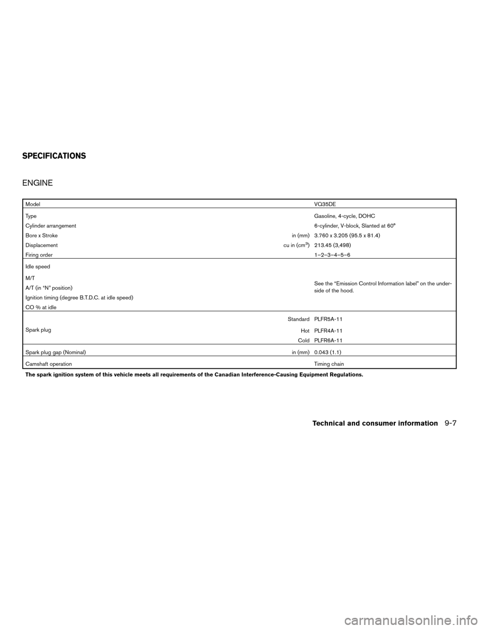
ENGINE
ModelVQ35DE
TypeGasoline, 4-cycle, DOHC
Cylinder arrangement6-cylinder, V-block, Slanted at 60°
Bore x Strokein (mm) 3.760 x 3.205 (95.5 x 81.4)
Displacementcu in (cm
3) 213.45 (3,498)
Firing order1–2–3–4–5–6
Idle speed
See the “Emission Control Information label” on the under-
side of the hood. M/T
A/T (in “N” position)
Ignition timing (degree B.T.D.C. at idle speed)
CO % at idle
Spark plugStandard PLFR5A-11
Hot PLFR4A-11
Cold PLFR6A-11
Spark plug gap (Nominal)in (mm) 0.043 (1.1)
Camshaft operationTiming chain
The spark ignition system of this vehicle meets all requirements of the Canadian Interference-Causing Equipment Regulations.
SPECIFICATIONS
Technical and consumer information9-7
ZREVIEW COPYÐ2005 Maxima(max)
Owners ManualÐUSA_English(nna)
09/01/04Ðtbrooks
X
Page 274 of 288

Due to legal requirements in some states and
Canadian Provinces, your vehicle may be re-
quired to be in what is called the “ready condi-
tion” for an Inspection/Maintenance (I/M) test of
the emission control system.
The vehicle is set to the “ready condition” when it
is driven through certain driving patterns. Usually,
the ready condition can be obtained by ordinary
usage of the vehicle.
If a powertrain system component is repaired or
the battery is disconnected, the vehicle may be
reset to a “not ready” condition. Before taking the
I/M test, check the vehicle’s
inspection/maintenance test readiness condi-
tion. Turn the ignition switch ON without starting
the engine. If the Malfunction Indicator Lamp
(MIL) comes on steady for 20 seconds and then
blinks for 10 seconds , the I/M test condition is
9not ready9. If the MIL does not blink after 20
seconds, the I/M test condition is9ready.9If the
MIL indicates the vehicle is in a9not ready9con-
dition, drive the vehicle through the following
pattern to set the vehicle to the ready condition. If
you cannot or do not want to perform the driving
pattern, a NISSAN dealer can conduct it for you.WARNING
Always drive the vehicle in a safe and
prudent manner according to traffic con-
ditions and obey all traffic laws.
1. Start the engine when the engine coolant
temperature gauge needle points to C. Al-
low the engine to idle until the gauge needle
points between the C and H (normal oper-
ating temperature) .
2. Accelerate the vehicle to 55 MPH (88
km/h) , then quickly release the accelerator
pedal completely and keep it released for at
least 10 seconds.
3. Quickly depress the accelerator pedal for a
moment, then drive the vehicle at a speed of
53 - 60 MPH (86 - 96 km/h) for at least 9
minutes.
4. Stop the vehicle.
5. Accelerate the vehicle to 35 MPH (55 km/h)
and maintain the speed for 20 seconds.
6. Repeat steps 4 through 5 at least 10 times.
7. Accelerate the vehicle to 55 MPH (88 km/h)
and maintain the speed for at least 3 min-
utes.8. Stop the vehicle. Place the transmission se-
lector lever in the P (Park) or N (Neutral)
position.
9. Turn the engine off.
10. Repeat steps1-8atleast one more time.
If steps 1 through 7 are interrupted, repeat the
preceding step. Any safe driving mode is accept-
able between steps. Do not stop the engine until
step 7 is completed.
READINESS FOR INSPECTION/
MAINTENANCE (I/M) TEST
9-20Technical and consumer information
ZREVIEW COPYÐ2005 Maxima(max)
Owners ManualÐUSA_English(nna)
09/01/04Ðtbrooks
X
Page 281 of 288
Fuel recommendation............9-3
FUEL ECON button............4-4, 4-9
Fuel Econ button
Control panel buttons..........4-4, 4-9
Fuses......................8-21
Fusible links...................8-23
G
Garage door opener, HomeLinkTUniversal
Transceiver...................2-43
Gascap.....................3-12
Gauge
Engine coolant temperature gauge.....2-5
Fuel gauge..................2-6
Odometer...................2-4
Speedometer.................2-4
Tachometer..................2-5
Trip odometer.................2-4
General maintenance..............8-2
Glove box....................2-32
Glove box lock.................2-32
Grocery hooks.................2-34
H
Hazard warning flasher switch.........2-24
Head restraints..................1-8
Active head restraint.............1-9
Headlight and turn signal switch........2-19
Heated seats..................2-25
Heated steering wheel.............2-26
Heater
Heater operation..............4-18HomeLinkTUniversal Transceiver.......2-43
Hood release...................3-9
Horn.......................2-24
I
Ignition switch..................5-4
Immobilizer system..........2-16, 3-2, 5-5
Important vehicle information label.......9-10
In-cabin microfilter...............8-16
Increasing fuel economy............5-15
Indicator lights and audible reminders
(See warning/indicator lights and audible
reminders).....................2-9
Instrument brightness control.........2-22
Instrument panel.................2-2
Interior light...................2-41
Interior trunk lid release.............3-11
ISOFIX child restraints.............1-25
J
Jump starting...................6-6
K
Key ........................3-2
Keyless entry system (See remote keyless entry
system)......................3-5L
Labels
Air conditioner specification label.....9-11
Emission control information label.....9-10
Engine serial number............9-10
F.M.V.S.S. certification label........9-10
Vehicle identification number (VIN) plate . .9-9
Warning labels (for SRS)..........1-49
LATCH (Lower Anchors and Tethers for CHildren)
System......................1-25
License plate
Installing the license plate.........9-11
Light
Air bag warning light.........1-49, 2-11
Brake light (See stop light).........8-26
Bulb check/instrument panel........2-9
Bulb replacement..............8-26
Charge warning light............2-10
Cornering light...............2-23
Fog light switch...............2-23
Headlight and turn signal switch......2-19
Interior light.................2-41
Light bulbs..................8-26
Low washer fluid warning light.......2-11
Passenger air bag and status light.....1-43
Personal lights...............2-42
Security indicator light...........1-43
Trunk light..................2-43
Warning/indicator lights and audible
reminders...................2-9
Lock
Child safety rear door lock..........3-5
Door locks..................3-3
Glove box lock...............2-32
10-3
ZREVIEW COPYÐ2005 Maxima(max)
Owners ManualÐUSA_English(nna)
09/01/04Ðtbrooks
X
Page 283 of 288
Rear window and outside mirror defroster
switch......................2-19
Recorders
Event data..................9-21
Refrigerant recommendation..........9-6
Registering your vehicle in another country. . .9-9
Remote keyless entry system..........3-5
Reporting safety defects (US only)......9-19
S
Safety
Child safety rear door lock..........3-5
Child seat belts...........1-18, 1-31
Reporting safety defects (US only). . . .9-19
Seat adjustment
Front manual seat adjustment........1-2
Front power seat adjustment........1-4
Seat belt
Child safety.................1-12
Infants and small children.........1-13
Injured Person................1-14
Larger children...............1-13
Precautions on seat belt usage......1-10
Pregnant women..............1-14
Seat belt extenders.............1-17
Seat belt maintenance...........1-17
Seat belts..................1-10
Shoulder belt height adjustment......1-16
Three-point type with retractor.......1-14
Seat belt warning light.............2-11
Seatback pockets................2-29
Seats
Adjustment..................1-2
Automatic drive positioner.........3-19Front seats..................1-2
Heated seats................2-25
Manual front seat adjustment........1-2
Rear seat...................1-6
Security indicator light.............1-43
Security system (Nissan vehicle immobilizer
system) , engine start.........2-16, 3-2, 5-5
Self-adjusting brakes..............8-21
Service manual order form...........9-22
Servicing air conditioner............4-20
Setting button
SETTING button............4-5, 4-11
Shift lock release................5-10
Shifting
Automatic transmission...........5-8
Manual transmission............5-11
Shoulder belt height adjustment........1-16
Spark plug replacement............8-15
Speedometer...................2-4
SRS warning label...............1-49
Starting
Before starting the engine..........5-6
Jump starting.................6-6
Precautions when starting and driving . . .5-2
Push starting.................6-8
Starting the engine..............5-6
Startup Screen
Control panel buttons............4-8
Startup screen display..............4-8
Steering
Heated steering wheel...........2-26
Power steering fluid.............8-11
Power steering system...........5-17
Steering wheel audio control switch......4-32
Stop light....................8-26
Storage.....................2-29Sun visors....................3-15
Sunglasses case................2-30
Sunglasses holder...............2-30
Sunroof.....................2-38
Supplemental air bag warning light . . .1-49, 2-11
Supplemental front impact air bag system . .1-42
Supplemental restraint system
Information and warning labels.......1-49
Precautions on supplemental restraint
system....................1-35
Supplemental restraint system
(Supplemental air bag system).........1-35
Switch
Autolight switch...............2-20
Automatic power window switch.....2-37
Fog light switch...............2-23
Hazard warning flasher switch.......2-24
Headlight and turn signal switch......2-19
Ignition switch................5-4
Power door lock switch...........3-4
Rear window and outside mirror defroster
switch....................2-19
Traction control system (TCS) off
switch....................2-26
Vehicle dynamic control (VDC) off
switch....................2-27
Windshield wiper and washer switch . . .2-18
T
Tachometer....................2-5
Temperature gauge
Engine coolant temperature gauge.....2-5
Engine oil pressure low/engine coolant
temperature high warning light.......2-10
10-5
ZREVIEW COPYÐ2005 Maxima(max)
Owners ManualÐUSA_English(nna)
09/01/04Ðtbrooks
X