tire size NISSAN MAXIMA 2006 A34 / 6.G Owners Manual
[x] Cancel search | Manufacturer: NISSAN, Model Year: 2006, Model line: MAXIMA, Model: NISSAN MAXIMA 2006 A34 / 6.GPages: 312, PDF Size: 4.88 MB
Page 33 of 312
WARNING
cAfter adjustment, release the adjust-
ment button and try to move the shoul-
der belt anchor up and down to make
sure it is securely fixed in position.
cThe shoulder belt anchor height should
be adjusted to the position best for you.
Failure to do so may reduce the effec-
tiveness of the entire restraint system
and increase the chance or severity of
injury in an accident.
SEAT BELT EXTENDERS
If, because of body size or driving position, it is
not possible to properly fit the lap-shoulder belt
and fasten it, an extender is available which is
compatible with the installed seat belts. The ex-
tender adds approximately 8 inches (200 mm) of
length and may be used for either the driver or
front passenger seating position. See a NISSAN
dealer for assistance if an extender is required.
WARNING
cOnly NISSAN seat belt extenders, made
by the same company which made the
original equipment seat belts, should
be used with NISSAN seat belts.cAdults and children who can use the
standard seat belt should not use an
extender. Such unnecessary use could
result in serious personal injury in the
event of an accident.
cNever use seat belt extenders to install
child restraints. If the child restraint is
not secured properly, the child could be
seriously injured in a collision or a sud-
den stop.
SEAT BELT MAINTENANCE
cTo clean the seat belt webbing,apply a
mild soap solution or any solution recom-
mended for cleaning upholstery or carpet.
Then wipe with a cloth and allow the seat
belts to dry in the shade. Do not allow the
seat belts to retract until they are completely
dry.
cIf dirt builds up in the shoulder belt
guideof the seat belt anchors, the seat
belts may retract slowly. Wipe the shoulder
belt guide with a clean, dry cloth.cPeriodically check to see that the seat
belt and the metal components,such as
buckles, tongues, retractors, flexible wires
and anchors, work properly. If loose parts,
deterioration, cuts or other damage on the
webbing is found, the entire seat belt as-
sembly should be replaced.
Safety—Seats, seat belts and supplemental restraint system1-17
ZREVIEW COPYÐ2006 Maxima(max)
Owners ManualÐUSA_English(nna)
06/22/05Ðtbrooks
X
Page 204 of 312
This procedure is described in the vehicle service
manual and can be performed by a NISSAN
dealer.
ANTI-LOCK BRAKE SYSTEM (ABS)
The anti-lock brake system controls the brakes so
the wheels do not lock when braking abruptly or
when braking on slippery surfaces. The system
detects the rotation speed at each wheel and
varies the brake fluid pressure to prevent each
wheel from locking and sliding. By preventing
wheel lockup, the system helps the driver main-
tain steering control and helps to minimize swerv-
ing and spinning on slippery surfaces.
Using the system
Depress the brake pedal and hold it down.
WARNING
Do not pump the brake pedal. Doing so
may result in increased stopping
distances.
Normal operation
The anti-lock brake system does not operate at
speeds below3-6MPH(5-10km/h) . (The
speeds vary according to road conditions.)
When driving, the anti-lock brake system con-
trols the wheels so they will not lock when brak-ing abruptly or when braking on a slippery road.
Thus, difficult steering and swerving of the ve-
hicle due to locked wheels is minimized. The
system detects the wheel rotation rate and elec-
tronically controls the pressure applied to each
brake. Slight vibration on the brake pedal accom-
panied by noise usually occurs while the ABS
system is operating. Such vibration and noise
encountered during abrupt braking is not a prob-
lem, but indicates that the system is functioning
properly. However, the pulsation may indicate
that road conditions are hazardous and extra care
is required while driving.
Self-test feature
The anti-lock brake system consists of electronic
sensors and hydraulic solenoids controlled by a
computer. The computer has a built-in diagnostic
feature that tests the system each time you start
the engine and move the vehicle at a low speed in
forward or reverse. When the self-test occurs,
you may hear a ‘‘clunk’’ noise and/or feel a pulsa-
tion in the brake pedal. This is normal and is not
an indication of any malfunction. If the computer
senses any malfunction, it switches the anti-lock
brake system off and turns on the ABS brake
warning light on the instrument panel. The brake
system then operates normally, but without anti-
lock assistance.If the light comes on during the self-test or while
driving, take the vehicle to a NISSAN dealer for
repair.
WARNING
cThe anti-lock brake system is a sophis-
ticated device, but it cannot prevent ac-
cidents resulting from careless or dan-
gerous driving techniques. It can help
maintain vehicle control during braking
on slippery surfaces, but remember that
the stopping distance on slippery sur-
faces will be longer than on normal
surfaces even with the anti-lock brake
system. Stopping distances may also
be longer on rough, gravel or snow cov-
ered roads, or if you are using tire
chains. Tire type and condition may also
affect braking effectiveness. Always
maintain a safe distance from the ve-
hicle in front of you. Ultimately, the re-
sponsibility for safety of self and others
rests in the hands of the driver.
cTire type and condition of tires may also
affect braking effectiveness.
cWhen replacing tires, install the speci-
fied size of tires on all four wheels.
5-18Starting and driving
ZREVIEW COPYÐ2006 Maxima(max)
Owners ManualÐUSA_English(nna)
06/22/05Ðtbrooks
X
Page 205 of 312
cWhen installing a spare tire, make sure
it is the proper size and type as speci-
fied on the tire placard. For tire placard
location information, refer to “Tire plac-
ard” in the “Technical and consumer
information” section of this manual.
cRefer to “Wheels and tires” in the
“Maintenance and do-it-yourself” sec-
tion of this manual.When accelerating on slippery surfaces the tire
may spin or slip. With the vehicle traction control
system (TCS) , sensors detect these movements
and control the braking and engine output to help
improve vehicle stability while accelerating.
cWhen the traction control system is operat-
ing, the slip indicator in the instrument panel
blinks.
cIf the slip indicator blinks, the vehicle is un-
der slippery conditions. Be sure to drive
carefully. See “Slip indicator light” and “Trac-
tion control system (TCS) off indicator light”
in the “Instruments and controls” section of
this manual.
cIf a malfunction occurs in the system,
the
andindicator lights
come on in the meter panel.
As long as these lights are on, the traction control
function is canceled. The vehicle will behave like
a vehicle without the system.
WARNING
cThe traction control system is designed
to help improve driving stability but
does not prevent accidents due to
abrupt steering operation at high
speeds or by careless or dangerous
driving techniques. Reduce vehicle
speed and be especially careful when
driving and cornering on slippery sur-
faces and always drive carefully.
cIf brake related parts such as brake
pads, rotors and calipers are not stan-
dard equipment or are extremely dete-
riorated, the traction control system
may not operate properly and the
indicator light may come on.
cDo not modify the vehicle’s suspension.
If suspension parts such as shock ab-
sorbers, struts, springs and bushings
are not standard equipment or are ex-
tremely deteriorated, the traction con-
trol system may not operate properly
and the
indicator light may come
on.
TRACTION CONTROL SYSTEM (TCS)
(if so equipped)
Starting and driving5-19
ZREVIEW COPYÐ2006 Maxima(max)
Owners ManualÐUSA_English(nna)
06/22/05Ðtbrooks
X
Page 208 of 312
DRAINING OF COOLANT WATER
If the vehicle is to be left outside without anti-
freeze, drain the cooling system, including the
engine block. Refill before operating the vehicle.
For details, see ‘‘Changing engine coolant’’ in the
‘‘Maintenance and do-it-yourself’’ section of this
manual.
TIRE EQUIPMENT
1. SUMMER tires have a tread designed to
provide superior performance on dry pave-
ment. However, the performance of these
tires will be substantially reduced in snowy
and icy conditions. If you operate your ve-
hicle on snowy or icy roads, NISSAN recom-
mends the use of MUD & SNOW or ALL
SEASON TIRES on all four wheels. Please
consult a NISSAN dealer for the tire type,
size, speed rating and availability informa-
tion.
2. For additional traction on icy roads, studded
tires may be used. However, some U.S.
states and Canadian provinces prohibit their
use. Check local, state and provincial laws
before installing studded tires.
Skid and traction capabilities of studded
snow tires on wet or dry surfaces may be
poorer than that of non-studded snow tires.3. Tire chains may be used.
CAUTION
Tire chains/cables cannot be installed on
P245/45R18 size tires. Installation of the
tire chains/cables on P245/45R18 size
tires will cause damage to the vehicle. If
you plan to use tire chains/cables, you
should install P225/55R17 size tires on
your vehicle.
Use of tire chains may be prohibited accord-
ing to location. Check the local laws before
installing tire chains. When installing tire
chains, make sure they are the proper size
for the tires on your vehicle and are installed
according to the chain manufacturer’s sug-
gestions.Use only SAE Class “S”
chains.Class “S” chains are used on ve-
hicles with restricted tire to vehicle clear-
ance. Vehicles that can use Class “S” chains
are designed to meet the minimum clear-
ances between the tire and the closest ve-
hicle suspension or body component re-
quired to accommodate the use of a winter
traction device (tire chains or cables) . The
minimum clearances are determined using
the factory equipped tire size. Other types
may damage your vehicle. Use chain ten-
sioners when recommended by the tire
chain manufacturer to ensure a tight fit.Loose end links of the tire chain must be
secured or removed to prevent the possibil-
ity of whipping action damage to the fenders
or underbody. If possible, avoid fully loading
your vehicle when using tire chains. In addi-
tion, drive at a reduced speed. Otherwise,
your vehicle may be damaged and/or vehicle
handling and performance may be adversely
affected.
Never install tire chains on spare tires. Do
not use tire chains on dry roads.
SPECIAL WINTER EQUIPMENT
It is recommended that the following items be
carried in the vehicle during winter:
cA scraper and stiff-bristled brush to remove
ice and snow from the windows and wiper
blades.
cA sturdy, flat board to be placed under the
jack to give it firm support.
cA shovel to dig the vehicle out of snowdrifts.
cExtra window washer fluid to refill the reser-
voir tank.
5-22Starting and driving
ZREVIEW COPYÐ2006 Maxima(max)
Owners ManualÐUSA_English(nna)
06/22/05Ðtbrooks
X
Page 264 of 312
cIncrease the cold tire inflation
pressure as indicated in(Check-
ing tire pressure(later in this sec-
tion when using the tires speci-
fied by NISSAN above 100 MPH
(162 km/h) where it is legal to do
so (on a race track for example) .
Failure to increase the cold tire
inflation pressure may result in
tire failure, loss of control and
possible injury. After such use,
readjust tire pressure.
cDo not drive your vehicle over 85
MPH (137 km/h) unless it is
equipped with high speed rated
tires. Driving faster than 85 MPH
(137 km/h) may result in tire fail-
ure, loss of control and possible
injury.
cFor additional information re-
garding tires, refer to “Important
Tire Safety Information” (US) or
“Tire Safety Information”
(Canada) in the Warranty Infor-
mation Booklet.
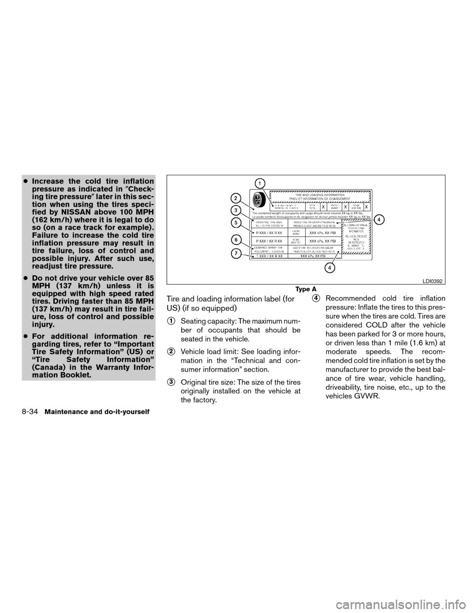
Tire and loading information label (for
US) (if so equipped)
s1Seating capacity: The maximum num-
ber of occupants that should be
seated in the vehicle.
s2Vehicle load limit: See loading infor-
mation in the “Technical and con-
sumer information” section.
s3Original tire size: The size of the tires
originally installed on the vehicle at
the factory.
s4Recommended cold tire inflation
pressure: Inflate the tires to this pres-
sure when the tires are cold. Tires are
considered COLD after the vehicle
has been parked for 3 or more hours,
or driven less than 1 mile (1.6 km) at
moderate speeds. The recom-
mended cold tire inflation is set by the
manufacturer to provide the best bal-
ance of tire wear, vehicle handling,
driveability, tire noise, etc., up to the
vehicles GVWR.
Type A
LDI0392
8-34Maintenance and do-it-yourself
ZREVIEW COPYÐ2006 Maxima(max)
Owners ManualÐUSA_English(nna)
06/23/05Ðtbrooks
X
Page 265 of 312

s5Tire size – refer to “Tire labeling” later
in this section.
s6ands7Spare tire size or compact
spare tire size (if so equipped) .
Tire and loading information label (for
US)
s1Seating capacity: The maximum num-
ber of occupants that should be
seated in the vehicle.
s2Vehicle load limit: See loading infor-
mation in the “Technical and con-
sumer information” section.
s3Recommended cold tire inflation
pressure: Inflate the tires to this pres-
sure when the tires are cold. Tires are
considered COLD after the vehicle
has been parked for 3 or more hours,
or driven less than 1 mile (1.6 km) at
moderate speeds. The recom-
mended cold tire inflation is set by the
manufacturer to provide the best bal-
ance of tire wear, vehicle handling,
driveability, tire noise, etc., up to the
vehicles GVWR.
Type B
LDI0434
Maintenance and do-it-yourself8-35
ZREVIEW COPYÐ2006 Maxima(max)
Owners ManualÐUSA_English(nna)
06/23/05Ðtbrooks
X
Page 266 of 312

s4Original tire size: The size of the tires
originally installed on the vehicle at
the factory.
s5Spare tire size or compact spare tire
size (if so equipped) .
Checking tire pressure
1. Remove the valve stem cap from the
tire.
2. Press the pressure gauge squarely
onto the valve stem. Do not press too
hard or force the valve stem side-
ways, or air will escape. If the hissing
of air escaping from the tire is heard
while checking the pressure, reposi-
tion the gauge to eliminate this leak-
age.3. Remove the gauge.
4. Read the tire pressure on the gauge
stem and compare to the specifica-
tion shown on the Tire and Loading
Information label.
5. Add air to the tire as needed. If too
much air is added, press the core of
the valve stem briefly with the tip of
the gauge stem to release pressure.
Recheck the pressure and add or
release air as needed.
6. Install the valve stem cap.
7. Check the pressure of all other tires,
including the spare.
LDI0393
8-36Maintenance and do-it-yourself
ZREVIEW COPYÐ2006 Maxima(max)
Owners ManualÐUSA_English(nna)
06/23/05Ðtbrooks
X
Page 267 of 312

Size Cold Tire Inflation
PressureHigh Speed/
Maximum Load
Cold Tire Inflation
Pressure
Front Original TireP225/55R17 95V 230 kPa, 33 PSI 240 kPa, 35 PSI
P245/45R18 96V 220 kPa, 32 PSI 260 kPa, 38 PSI
Rear Original TireP225/55R17 95V 230 kPa, 33 PSI 240 kPa, 35 PSI
P245/45R18 96V 220 kPa, 32 PSI 260 kPa, 38 PSI
Spare Tire T145/80*17 420 kPa, 60 PSI N/A
*: “R” or “D” depending on tire manufacturer
TIRE LABELING
Federal law requires tire manufacturers to
place standardized information on the
sidewall of all tires. This information iden-
tifies and describes the fundamental
characteristics of the tire and also pro-
vides the tire identification number (TIN)
for safety standard certification. The TIN
can be used to identify the tire in case of a
recall.
WDI0394
Maintenance and do-it-yourself8-37
ZREVIEW COPYÐ2006 Maxima(max)
Owners ManualÐUSA_English(nna)
06/23/05Ðtbrooks
X
Page 268 of 312

s1Tire size (example: P215/65R15 95H)
1. P: The9P9indicates the tire is de-
signed for passenger vehicles.
2. Three-digit number: This number
gives the width in millimeters of the
tire from sidewall edge to sidewall
edge.
3. Two-digit number: This number,
known as the aspect ratio, gives the
tire’s ratio of height to width.
4. R: The9R9stands for radial.5. Two-digit number: This number is the
wheel or rim diameter in inches.
6. Two- or three-digit number: This
number is the tire’s load index. It is a
measurement of how much weight
each tire can support. You may not
find this information on all tires be-
cause it is not required by law.
7. Tire speed rating. You should not
drive the vehicle faster than the tire
speed rating.
WDI0395
8-38Maintenance and do-it-yourself
ZREVIEW COPYÐ2006 Maxima(max)
Owners ManualÐUSA_English(nna)
06/23/05Ðtbrooks
X
Page 269 of 312

s2TIN (Tire Identification Number) for a
new tire (example: DOT XX XX XXX
XXXX)
1.
DOT: Abbreviation for the9Department
Of Transportation.9The symbol can be
placed above, below or to the left or
right of Tire Identification Number.
2. Two-digit code: Manufacturer’s
identification mark
3. Two-digit code: Tire size
4. Three-digit code: Tire type code
(Optional)5.
Three-digit code: Date of Manufacture
6. Four numbers represent the week
and year the tire was built. For ex-
ample, the numbers 3103 means the
31st week of 2003. If these numbers
are missing, then look on the other
sidewall of the tire.
s3Tire ply composition and material
The number of layers or plies of rubber-
coated fabric in the tire. Tire manufactur-
ers also must indicate the materials in the
tire, which include steel, nylon, polyester,
and others.
s4Maximum permissible inflation pres-
sure
This number is the greatest amount of air
pressure that should be put in the tire. Do
not exceed the maximum permissible in-
flation pressure.
s5Maximum load rating
This number indicates the maximum load
in kilograms and pounds that can be car-
ried by the tire. When replacing the tires
on the vehicle, always use a tire that has
the same load rating as the factory in-
stalled tire.
s6Term of ”tubeless” or ”tube type”
Indicates whether the tire requires an in-
ner tube (“tube type”) or not (“tubeless”) .
s7The word ”radial”
The word9radial9is shown if the tire has
radial structure.
s8Manufacturer or brand name
Manufacturer or brand name is shown.
WDI0396
Maintenance and do-it-yourself8-39
ZREVIEW COPYÐ2006 Maxima(max)
Owners ManualÐUSA_English(nna)
06/23/05Ðtbrooks
X