headrest NISSAN MAXIMA 2010 Owner´s Manual
[x] Cancel search | Manufacturer: NISSAN, Model Year: 2010, Model line: MAXIMA, Model: NISSAN MAXIMA 2010Pages: 457, PDF Size: 4.66 MB
Page 8 of 457
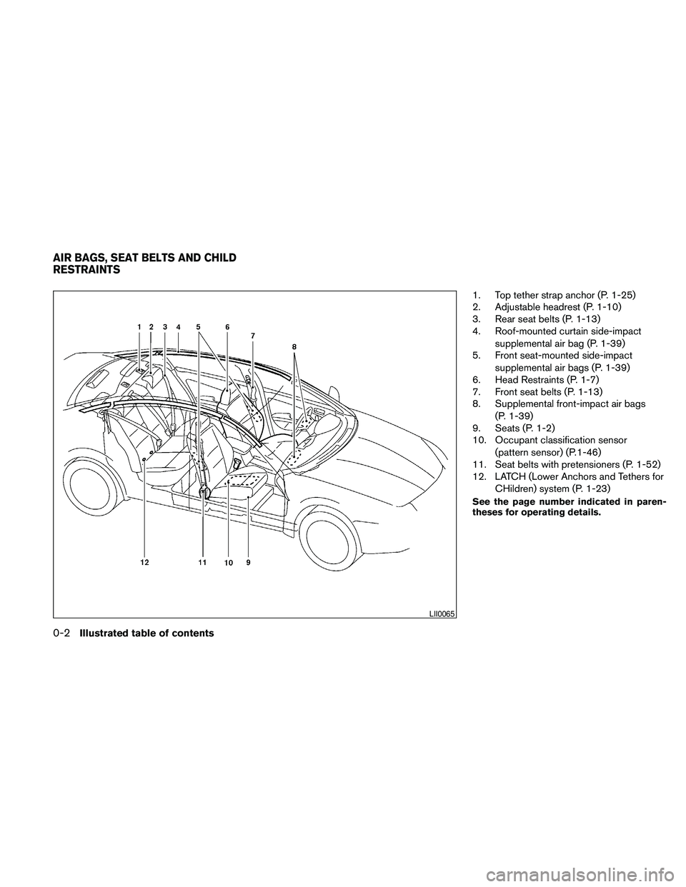
1. Top tether strap anchor (P. 1-25)
2. Adjustable headrest (P. 1-10)
3. Rear seat belts (P. 1-13)
4. Roof-mounted curtain side-impact
supplemental air bag (P. 1-39)
5. Front seat-mounted side-impact
supplemental air bags (P. 1-39)
6. Head Restraints (P. 1-7)
7. Front seat belts (P. 1-13)
8. Supplemental front-impact air bags
(P. 1-39)
9. Seats (P. 1-2)
10. Occupant classification sensor
(pattern sensor) (P.1-46)
11. Seat belts with pretensioners (P. 1-52)
12. LATCH (Lower Anchors and Tethers for
CHildren) system (P. 1-23)
See the page number indicated in paren-
theses for operating details.
LII0065
AIR BAGS, SEAT BELTS AND CHILD
RESTRAINTS
0-2Illustrated table of contents
Page 17 of 457
1 Safety—Seats, seat belts and
supplemental restraint system
Seats............................................1-2
Front power seat adjustment.....................1-3
Folding rear seat (if so equipped).................1-5
Head restraints.................................1-7
Adjustable headrest (if so equipped).............1-10
Seat belts.......................................1-13
Precautions on seat belt usage..................1-13
Pregnant women..............................1-16
Injured persons................................1-16
Three-point type seat belt with retractor..........1-16
Seat belt extenders............................1-19
Seat belt maintenance.........................1-19
Child safety......................................1-20
Infants........................................1-20
Small children.................................1-20
Larger children................................1-21
Child restraints...................................1-21Precautions on child restraints..................1-21
LATCH (Lower Anchors and Tethers for
CHildren) System.............................1-23
Rear-facing child restraint installation using
LATCH.......................................1-25
Rear-facing child restraint installation using
the seat belts.................................1-28
Forward-facing child restraint installation
using LATCH..................................1-30
Forward-facing child restraint installation
using the seat belts............................1-32
Installing top tether strap.......................1-35
Booster seats.................................1-36
Supplemental restraint system.....................1-39
Precautions on supplemental restraint
system.......................................1-39
Supplemental air bag warning labels.............1-53
Supplemental air bag warning light..............1-53
Page 26 of 457
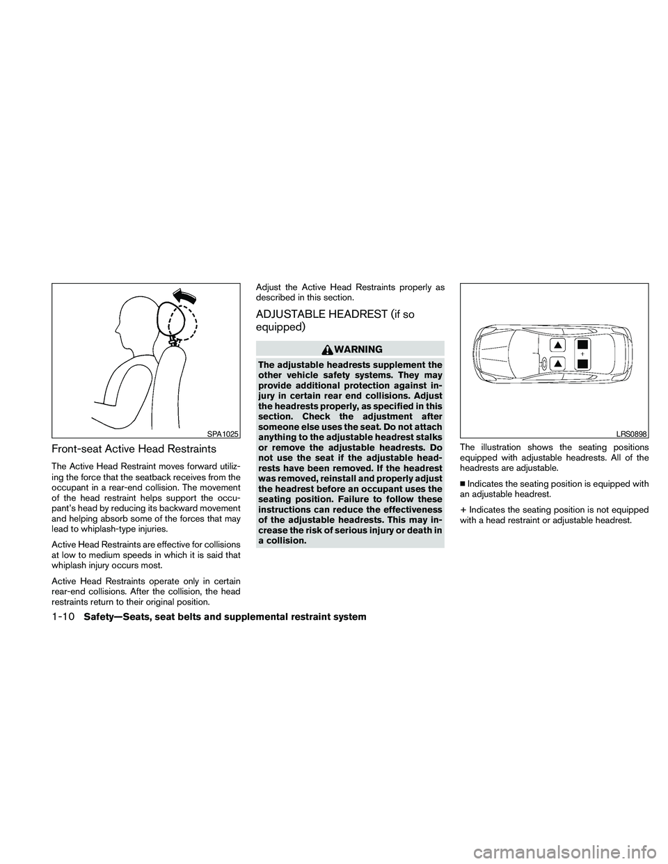
Front-seat Active Head Restraints
The Active Head Restraint moves forward utiliz-
ing the force that the seatback receives from the
occupant in a rear-end collision. The movement
of the head restraint helps support the occu-
pant’s head by reducing its backward movement
and helping absorb some of the forces that may
lead to whiplash-type injuries.
Active Head Restraints are effective for collisions
at low to medium speeds in which it is said that
whiplash injury occurs most.
Active Head Restraints operate only in certain
rear-end collisions. After the collision, the head
restraints return to their original position.Adjust the Active Head Restraints properly as
described in this section.
ADJUSTABLE HEADREST (if so
equipped)
WARNING
The adjustable headrests supplement the
other vehicle safety systems. They may
provide additional protection against in-
jury in certain rear end collisions. Adjust
the headrests properly, as specified in this
section. Check the adjustment after
someone else uses the seat. Do not attach
anything to the adjustable headrest stalks
or remove the adjustable headrests. Do
not use the seat if the adjustable head-
rests have been removed. If the headrest
was removed, reinstall and properly adjust
the headrest before an occupant uses the
seating position. Failure to follow these
instructions can reduce the effectiveness
of the adjustable headrests. This may in-
crease the risk of serious injury or death in
a collision.The illustration shows the seating positions
equipped with adjustable headrests. All of the
headrests are adjustable.
nIndicates the seating position is equipped with
an adjustable headrest.
+ Indicates the seating position is not equipped
with a head restraint or adjustable headrest.
SPA1025LRS0898
1-10Safety—Seats, seat belts and supplemental restraint system
Page 27 of 457
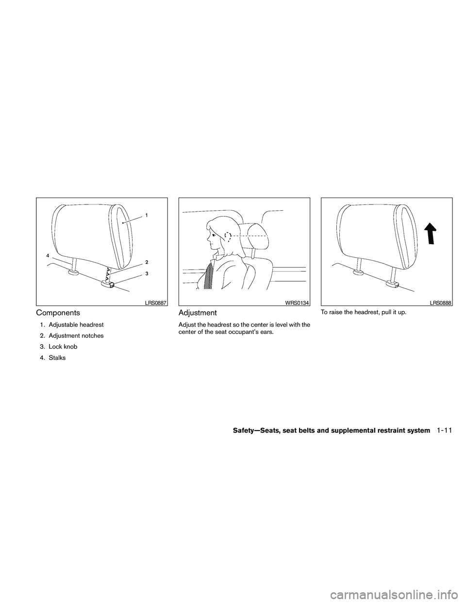
Components
1. Adjustable headrest
2. Adjustment notches
3. Lock knob
4. Stalks
Adjustment
Adjust the headrest so the center is level with the
center of the seat occupant’s ears.To raise the headrest, pull it up.
LRS0887WRS0134LRS0888
Safety—Seats, seat belts and supplemental restraint system1-11
Page 28 of 457
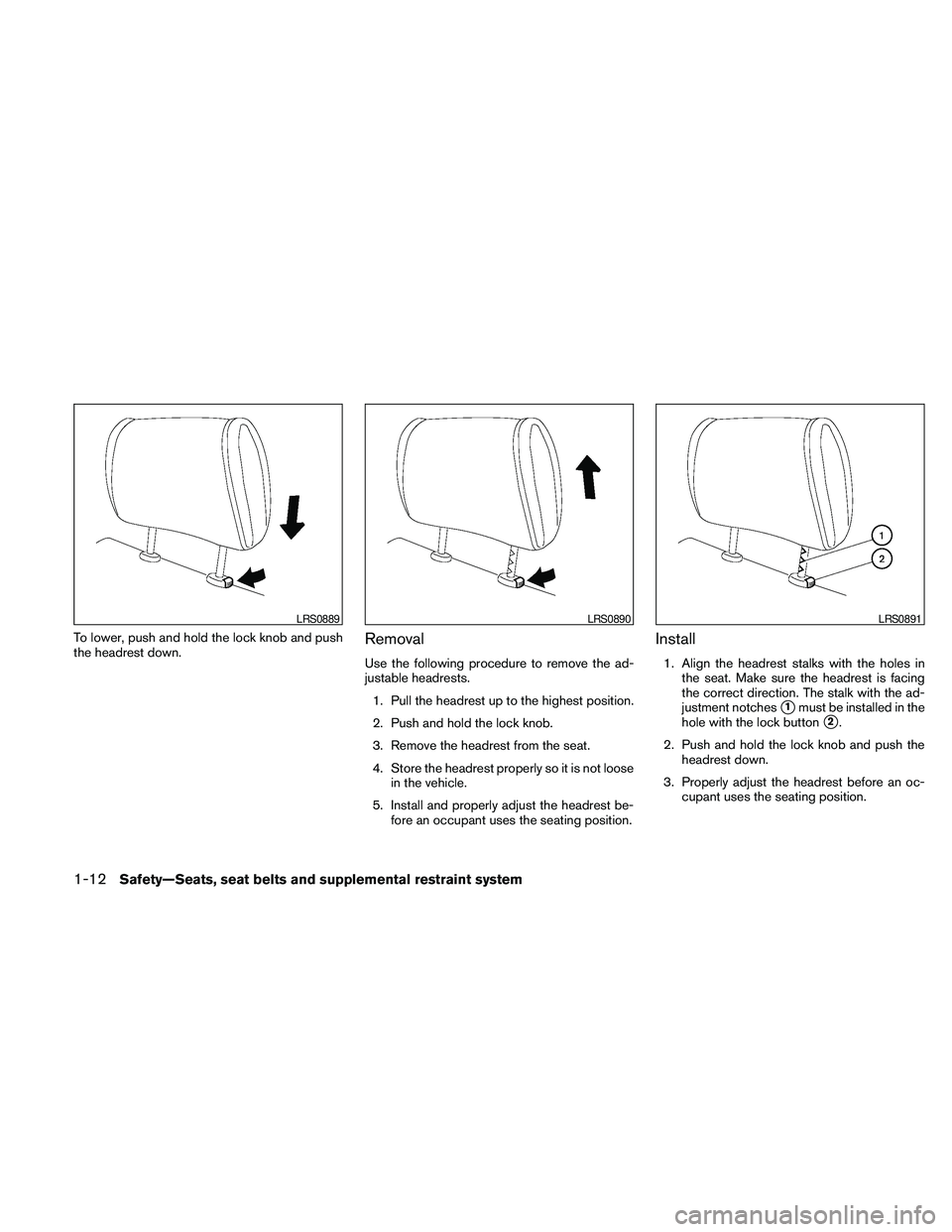
To lower, push and hold the lock knob and push
the headrest down.Removal
Use the following procedure to remove the ad-
justable headrests.
1. Pull the headrest up to the highest position.
2. Push and hold the lock knob.
3. Remove the headrest from the seat.
4. Store the headrest properly so it is not loose
in the vehicle.
5. Install and properly adjust the headrest be-
fore an occupant uses the seating position.
Install
1. Align the headrest stalks with the holes in
the seat. Make sure the headrest is facing
the correct direction. The stalk with the ad-
justment notches
s1must be installed in the
hole with the lock button
s2.
2. Push and hold the lock knob and push the
headrest down.
3. Properly adjust the headrest before an oc-
cupant uses the seating position.
LRS0889LRS0890LRS0891
1-12Safety—Seats, seat belts and supplemental restraint system
Page 47 of 457
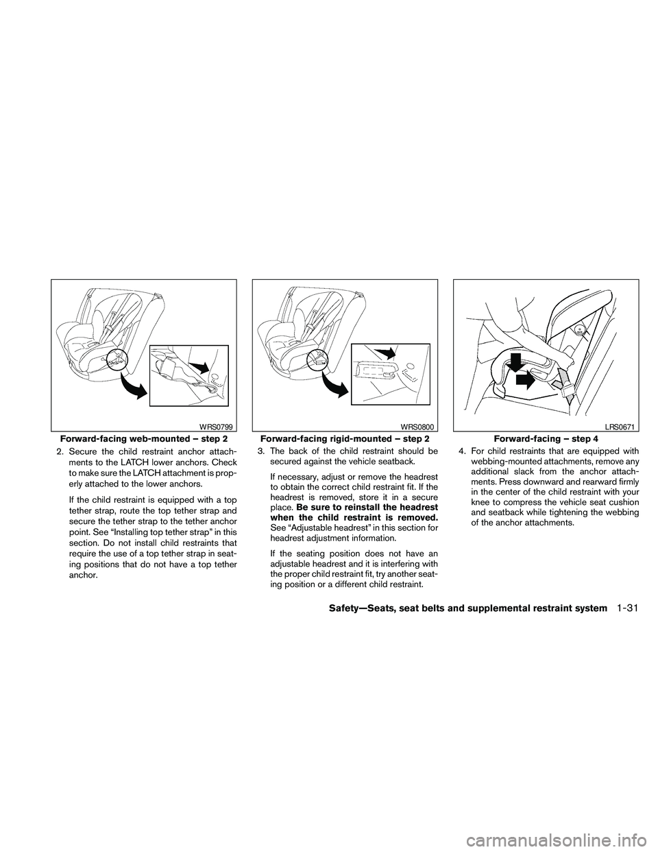
2. Secure the child restraint anchor attach-
ments to the LATCH lower anchors. Check
to make sure the LATCH attachment is prop-
erly attached to the lower anchors.
If the child restraint is equipped with a top
tether strap, route the top tether strap and
secure the tether strap to the tether anchor
point. See “Installing top tether strap” in this
section. Do not install child restraints that
require the use of a top tether strap in seat-
ing positions that do not have a top tether
anchor.3. The back of the child restraint should be
secured against the vehicle seatback.
If necessary, adjust or remove the headrest
to obtain the correct child restraint fit. If the
headrest is removed, store it in a secure
place.Be sure to reinstall the headrest
when the child restraint is removed.
See “Adjustable headrest” in this section for
headrest adjustment information.
If the seating position does not have an
adjustable headrest and it is interfering with
the proper child restraint fit, try another seat-
ing position or a different child restraint.4. For child restraints that are equipped with
webbing-mounted attachments, remove any
additional slack from the anchor attach-
ments. Press downward and rearward firmly
in the center of the child restraint with your
knee to compress the vehicle seat cushion
and seatback while tightening the webbing
of the anchor attachments.
Forward-facing web-mounted – step 2
WRS0799
Forward-facing rigid-mounted – step 2
WRS0800
Forward-facing – step 4
LRS0671
Safety—Seats, seat belts and supplemental restraint system1-31
Page 49 of 457
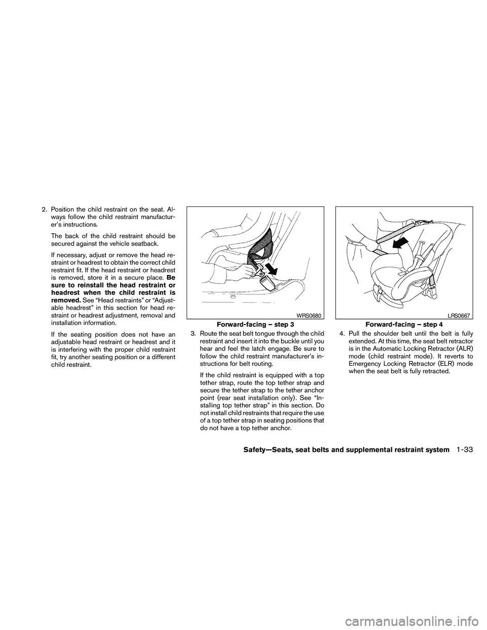
2. Position the child restraint on the seat. Al-
ways follow the child restraint manufactur-
er’s instructions.
The back of the child restraint should be
secured against the vehicle seatback.
If necessary, adjust or remove the head re-
straint or headrest to obtain the correct child
restraint fit. If the head restraint or headrest
is removed, store it in a secure place.Be
sure to reinstall the head restraint or
headrest when the child restraint is
removed.See “Head restraints” or “Adjust-
able headrest” in this section for head re-
straint or headrest adjustment, removal and
installation information.
If the seating position does not have an
adjustable head restraint or headrest and it
is interfering with the proper child restraint
fit, try another seating position or a different
child restraint.3. Route the seat belt tongue through the child
restraint and insert it into the buckle until you
hear and feel the latch engage. Be sure to
follow the child restraint manufacturer’s in-
structions for belt routing.
If the child restraint is equipped with a top
tether strap, route the top tether strap and
secure the tether strap to the tether anchor
point (rear seat installation only) . See “In-
stalling top tether strap” in this section. Do
not install child restraints that require the use
of a top tether strap in seating positions that
do not have a top tether anchor.4. Pull the shoulder belt until the belt is fully
extended. At this time, the seat belt retractor
is in the Automatic Locking Retractor (ALR)
mode (child restraint mode) . It reverts to
Emergency Locking Retractor (ELR) mode
when the seat belt is fully retracted.
Forward-facing – step 3
WRS0680
Forward-facing – step 4
LRS0667
Safety—Seats, seat belts and supplemental restraint system1-33
Page 54 of 457

3. The booster seat should be positioned on
the vehicle seat so that it is stable.
If necessary, adjust or remove the head re-
straint or headrest to obtain the correct
booster seat fit. If the head restraint or head-
rest is removed, store it in a secure place.Be
sure to reinstall the head restraint or
headrest when the booster seat is re-
moved.See “Head restraints” or “Adjust-
able headrests” in this section for head re-
straint or headrest adjustment, removal and
installation information.If the seating position does not have an
adjustable head restraint or headrest and it
is interfering with the proper booster seat fit,
try another seating position or a different
booster seat.
4. Position the lap portion of the seat belt low
and snug on the child’s hips. Be sure to
follow the booster seat manufacturer’s in-
structions for adjusting the seat belt routing.
5. Pull the shoulder belt portion of the seat belt
toward the retractor to take up extra slack.
Be sure the shoulder belt is positioned
across the top, middle portion of the child’s
shoulder. Be sure to follow the booster seat
manufacturer’s instructions for adjusting the
seat belt routing.
6. Follow the warnings, cautions and instruc-
tions for properly fastening a seat belt
shown in “Three-point type seat belt with
retractor” earlier in this section.7. If the booster seat is installed in the front
passenger seat, place the ignition switch in
the ON position. The front passenger air bag
status light
may or may not illuminate,
depending on the size of the child and the
type of booster seat being used. See “Front
passenger air bag and status light” later in
this section.
Front passenger position
LRS0454LRS0865
1-38Safety—Seats, seat belts and supplemental restraint system
Page 338 of 457
2. Place the ignition switch in the OFF or
LOCK position, and wait approximately 10
seconds.
3. Repeat steps 1 and 2.
4. Restart the engine while holding the device
(which may have caused the interference)
separate from the registered key.
If the no start condition re-occurs, NISSAN rec-
ommends placing the registered key on a sepa-
rate key ring to avoid interference from other
devices.cMake sure the area around the vehicle is
clear.
cCheck fluid levels such as engine oil, cool-
ant, brake fluid, and window washer fluid as
frequently as possible, or at least whenever
you refuel.
cCheck that all windows and lights are clean.
cVisually inspect tires for their appearance
and condition. Also check tires for proper
inflation.
cLock all doors.
cPosition seat and adjust head restraints and
headrests (if so equipped) .
cAdjust inside and outside mirrors.
cFasten seat belts and ask all passengers to
do likewise.
cCheck the operation of warning lights when
the ignition switch is pushed to the ON
position. See “Warning/indicator lights and
audible reminders” in the “Instruments and
controls” section of this manual.1. Apply the parking brake.
2. Move the shift selector to P (Park) or N
(Neutral) . P (Park) is recommended.
The starter is designed not to operate if
the shift selector is in any of the driving
positions.
3. Push the ignition switch to the ON position.
Depress the brake pedal and push the igni-
tion switch to start the engine.
To start the engine immediately, push and
release the ignition switch while depressing
the brake pedal with the ignition switch in
any position.
cIf the engine is very hard to start in ex-
tremely cold weather or when restarting,
depress the accelerator pedal a little (ap-
proximately 1/3 to the floor) and while
holding, crank the engine. Release the
accelerator pedal when the engine starts.
cIf the engine is very hard to start because
it is flooded, depress the accelerator
pedal all the way to the floor and hold it.
Push the ignition switch to the ON posi-
tion to start cranking the engine. After 5 or
6 seconds, stop cranking by pushing the
ignition switch to LOCK. After cranking
the engine, release the accelerator pedal.
Crank the engine with your foot off the
BEFORE STARTING THE ENGINE STARTING THE ENGINE
5-10Starting and driving
Page 381 of 457

When driving in areas using road salt or other
corrosive materials, check lubrication frequently.
Lights*Clean the headlights on a regular basis.
Make sure that the headlights, stop lights, tail
lights, turn signal lights, and other lights are all
operating properly and installed securely. Also
check headlight aim.
Road wheel nuts (lug nuts)*When checking
the tires, make sure no wheel nuts are missing,
and check for any loose wheel nuts. Tighten if
necessary.
Tire rotation*Tires should be rotated every
7,500 miles (12,000 km) .
Tires*Check the pressure with a gauge often
and always prior to long distance trips. If neces-
sary, adjust the pressure in all tires, including the
spare, to the pressure specified. Check carefully
for damage, cuts or excessive wear.
Tire Pressure Monitoring System (TPMS)
transmitter componentsReplace the TPMS
transmitter grommet seal, valve core and cap
when the tires are replaced due to wear or age.
Wheel alignment and balanceIf the vehicle
should pull to either side while driving on a
straight and level road, or if you detect uneven or
abnormal tire wear, there may be a need for wheelalignment. If the steering wheel or seat vibrates at
normal highway speeds, wheel balancing may be
needed.
cFor additional information regarding tires,
refer to “Important Tire Safety Information”
(US) or “Tire Safety Information” (Canada) in
the Warranty Information Booklet.
WindshieldClean the windshield on a regular
basis. Check the windshield at least every six
months for cracks or other damage. Have a dam-
aged windshield repaired by a qualified repair
facility.
Windshield wiper blades*Check for cracks or
wear if they do not wipe properly.
Inside the vehicle
The maintenance items listed here should be
checked on a regular basis, such as when per-
forming periodic maintenance, cleaning the ve-
hicle, etc.
Additional information on the following
items with an “*” is found later in this sec-
tion.
Accelerator pedalCheck the pedal for smooth
operation and make sure the pedal does not bind
or require uneven effort. Keep the floor mat away
from the pedal.Brake pedalCheck the pedal for smooth opera-
tion. If the brake pedal suddenly goes down fur-
ther than normal, the pedal feels spongy or the
vehicle seems to take longer to stop, see a
NISSAN dealer immediately. Keep the floor mat
away from the pedal.
BrakesCheck that the brakes do not pull the
vehicle to one side when applied.
Continuously Variable Transmission (CVT)
P (Park) position mechanism:On a fairly
steep hill check that the vehicle is held securely
with the shift selector in the P (Park) position
without applying any brakes.
Parking brakeCheck the parking brake opera-
tion regularly. The vehicle should be securely held
on a fairly steep hill with only the parking brake
applied. If the parking brake needs adjustment,
see a NISSAN dealer.
SeatsCheck seat position controls such as seat
adjusters, seatback recliner, etc. to ensure they
operate smoothly and all latches lock securely in
every position. Check that the head restraints and
headrests move up and down smoothly and the
locks (if so equipped) hold securely in all latched
positions.
Maintenance and do-it-yourself8-3