cvt NISSAN MAXIMA 2018 Owner´s Manual
[x] Cancel search | Manufacturer: NISSAN, Model Year: 2018, Model line: MAXIMA, Model: NISSAN MAXIMA 2018Pages: 428, PDF Size: 4.85 MB
Page 96 of 428
∙ If the light illuminates while driving,avoid sudden steering maneuvers or
abrupt braking, reduce vehicle speed,
pull off the road to a safe location and
stop the vehicle as soon as possible.
Driving with under-inflated tires may
permanently damage the tires and in-
crease the likelihood of tire failure. Se-
rious vehicle damage could occur and
may lead to an accident and could re-
sult in serious personal injury or
death. Check the tire pressure for all
four tires. Adjust the tire pressure to
the recommended COLD tire pressure
show on the Tire and Loading Infor-
mation label located in the driver’s
door opening to turn the low tire pres-
sure warning light off. If the light still
illuminates while driving af ter adjust-
ing the tire pressure, a tire may be flat
or the TPMS may be malfunctioning. If
you have a flat tire, replace it with a
spare tire as soon as possible. If no tire
is flat and all tires are properly in-
flated, have the vehicle checked. It is
recommended that you visit a NISSAN
dealer for this service. ∙ When replacing a wheel without the
TPMS such as the spare tire, the TPMS
will not function and the low tire pres-
sure warning light will flash for ap-
proximately 1 minute. The light will re-
main on af ter 1 minute. Have your
tires replaced and/or TPMS system
reset as soon as possible. It is recom-
mended that you visit a NISSAN dealer
for these services.
∙ Replacing tires with those not origi- nally specified by NISSAN could affect
the proper operation of the TPMS.
CAUTION
∙ The TPMS is not a substitute for theregular tire pressure check. Be sure to
check the tire pressure regularly.
∙ If the vehicle is being driven at speeds of less than 16 mph (25 km/h), the
TPMS may not operate correctly.
∙ Be sure to install the specified size of tires to the four wheels correctly.
Master warning light
The master warning light illuminates
whenever there is an active warning that
can be reviewed in the “warnings review” content page in the meter, or if there is a
red-level warning being displayed (which
cannot be dismissed). The master warning
light will illuminate red if a red-level warning
is being displayed, or yellow otherwise.
∙ Push Engine Start Lock Warning
∙ Key Fob Removed from Vehicle Warning
∙ Incorrect Key (RED)
∙ Door/Trunk Open (vehicle stationary)
∙ Trunk Open (vehicle moving)
∙ Door Open (RED with vehicle moving)
∙ Parking Brake ON (RED)
∙ Low Washer Fluid
∙ I-Key System Fault
∙ Low Tire Pressure
∙ CVT Warning
∙ Sonar Parking Sensor Error
∙ LED Headlight Failure (RED if no other red warnings are active)
∙ Chassis Control warning
For additional information, refer to “Vehicle
information display” in this section.
2-12Instruments and controls
Page 111 of 428
VEHICLE INFORMATION DISPLAY
WARNINGS AND INDICATORS
1. No Key Detected
2. Key ID Incorrect
3. Key Battery Low
4. I-Key System Error: See Owner’sManual
5. Shif t to Park
6. Push brake and start switch to drive
7. Engine start operation for Intelligent Key system (if I-Key battery level is low)
8. Release Parking Brake
9. Low Fuel
10. Low Washer Fluid
11. Tire Pressure Low – Add Air
12. Door/Trunk Open
13. Alarm - Time for a break? (if so equipped)
14. Power will turn off to save the battery
15. Power turned off to save the battery
16. Reminder: Turn OFF Headlights 17. Headlight System Error: See Owner’s
Manual (if so equipped)
18. Sensor (if so equipped)
19. Park Sensor (if so equipped)
20. Parking Sensor Error: See Owner’s Manual (if so equipped)
21. Blind Spot Warning (BSW) and Rear Cross Traffic Alert (RCTA) indicator (if so
equipped)
22. Malfunction: See Owner’s Manual (if so equipped)
23. Chassis Control System Error: See Owner’s Manual (if so equipped)
24. Cruise control indicator (if so equipped)
25. Intelligent Cruise Control (ICC) indicator (if so equipped)
26. Driver Attention Alert — Take a Break? (if so equipped)
27. Driver Attention Alertness Malfunction (if so equipped)
28. Shipping Mode On Push Storage Fuse
29. CVT Error: See Owner’s Manual
30. SPORT
31. Illumination indicator 32. Transmission Shif t Position indicator
33. Outside Temperature Display
34. Low Outside Temperature Alert
35. Oil and Filter
36. Tire
37. Other
38. Loose Fuel Cap
39. Unavailable: Front Radar Obstruction (if
so equipped)
40. Side Radar Obstruction (if so equipped)
No Key Detected
This warning appears when the Intelligent
Key is lef t outside the vehicle with the igni-
tion switch in the ON position. Make sure
the Intelligent Key is inside the vehicle.
For additional information, refer to “NISSAN
Intelligent Key®” in the “Pre-driving checks
and adjustments” section of this manual.
Key ID Incorrect
This warning appears when the ignition
switch is placed from the OFF position and
the Intelligent Key is not recognized by the
system. You cannot start the engine with
an unregistered key.
Instruments and controls2-27
Page 114 of 428
For additional information, refer to “Blind
Spot Warning (BSW)” and “Rear Cross Traffic
Alert (RCTA)” in the “Starting and driving”
section of this manual.
Malfunction: See Owner’s Manual (if so
equipped)
This warning appears when one or more of
the following systems (if so equipped) is
not functioning properly:∙ Blind Spot Warning (BSW)
∙ Rear Cross Traffic Alert (RCTA)
If one or more of these warning appears,
have the system checked. It is recom-
mended that you visit a NISSAN dealer for
this service.
Chassis Control System Error: See Own-
er’s Manual (if so equipped)
This warning appears if the Integrated
Dynamics-control Module detects an error
in the Intelligent Trace Control, Intelligent
Engine Brake, or the Active Ride Control
systems. Have the system checked. It is
recommended that you visit a NISSAN
dealer for this service. For additional infor-
mation, refer to “Chassis control” in the
“Starting and driving” section of this
manual. Cruise control indicator (if so equipped)
This indicator shows the cruise control sys-
tem status.
When cruise control is activated, a green
circle will illuminate to indicate it is set. The
vehicle information display will also display
the speed the cruise control was set at. If
you accelerate past the set speed, the
speed will blink until you either cancel
cruise control or go back to the set speed. If
cruise control is on and canceled, the
speed will be displayed to show the speed
the vehicle will return to if the resume but-
ton is activated.
Intelligent Cruise Control (ICC) indicator
(if so equipped)
This indicator shows the Intelligent Cruise
Control (ICC) system status. The status is
shown by the color. For additional informa-
tion, refer to “Intelligent Cruise Control (ICC)”
in the “Starting and driving” section of this
manual.
Driver Attention Alert - Take a Break? (if
so equipped)
This alert appears when the system has
detected that the driver may be displaying
fatigue or a lack of attention.Driver Attention Alert Malfunction (if so
equipped)
This warning appears when the Driver At-
tention Alert system is not functioning
properly. For additional information, refer to
“Intelligent Driver Alertness (I-DA)” in the
“Starting and driving” section of this
manual.
Shipping Mode On Push Storage Fuse
This warning may appear if the extended
storage switch is not pushed in. When this
warning appears, push in the extended
storage switch to turn off the warning. For
additional information, refer to “Extended
storage switch” in this section.
CVT Error: See Owner’s Manual
This warning illuminates when there is a
problem with the CVT system. If this warn-
ing comes on, have the system checked. It
is recommended that you visit a NISSAN
dealer for this service.
SPORT
This indicator illuminates when sport
mode is activated. The sport mode screen
will remain on for about 6 seconds unless
the driver dismisses the notification early
using the vehicle information display
2-30Instruments and controls
Page 225 of 428
5 Starting and driving
Precautions when starting and driving..........5-4
Exhaust gas (carbon monoxide) ..............5-4
Three-way catalyst ...........................5-4
Tire Pressure Monitoring System
(TPMS)........................................5-5
Avoiding collision and rollover ................5-8
Off-roadrecovery ............................5-9
Rapid air pressure loss .......................5-9
Drinking alcohol/drugs and driving ..........5-10
Push-button ignition switch ....................5-10
Operating range .............................. 5-11
Push-button ignition switch positions .......5-12
Emergency engine shut off ..................5-13
NISSAN Intelligent Key® battery
discharge ................................... 5-13
NISSAN Vehicle Immobilizer System .........5-14
Before starting the engine ......................5-14
Starting the engine ............................. 5-14
Remote Engine Start ........................ 5-15
Driving the vehicle .............................. 5-16
Continuously Variable Transmission
(CVT) ........................................ 5-16
Parking brake .................................. 5-22
Drive Mode Selector ............................ 5-22Normal mode
............................... 5-23
Sport mode ................................. 5-23
Blind Spot Warning (BSW) (if so equipped) .......5-23
BSW system operation ......................5-25
How to enable/disable the BSW system .....5-26
BSW system limitations ......................5-27
BSW driving situations .......................5-28
System temporarily unavailable .............5-31
System maintenance ........................ 5-32
Rear Cross Traffic Alert (RCTA) (if so equipped) . . 5-33 RCTA system operation ......................5-34
How to enable/disable the RCTA
system ...................................... 5-36
RCTA system limitations .....................5-37
System temporarily unavailable .............5-39
System maintenance ........................ 5-40
Cruise control (if so equipped) ..................5-41
Pr
ecautions on cruise control ................5-41
Cruise control operations ....................5-42
Intelligent Cruise Control (ICC) (if so equipped) . . 5-43 ICC system operation .......................5-44
The ICC switch .............................. 5-46
ICC system limitations .......................5-52
Page 240 of 428
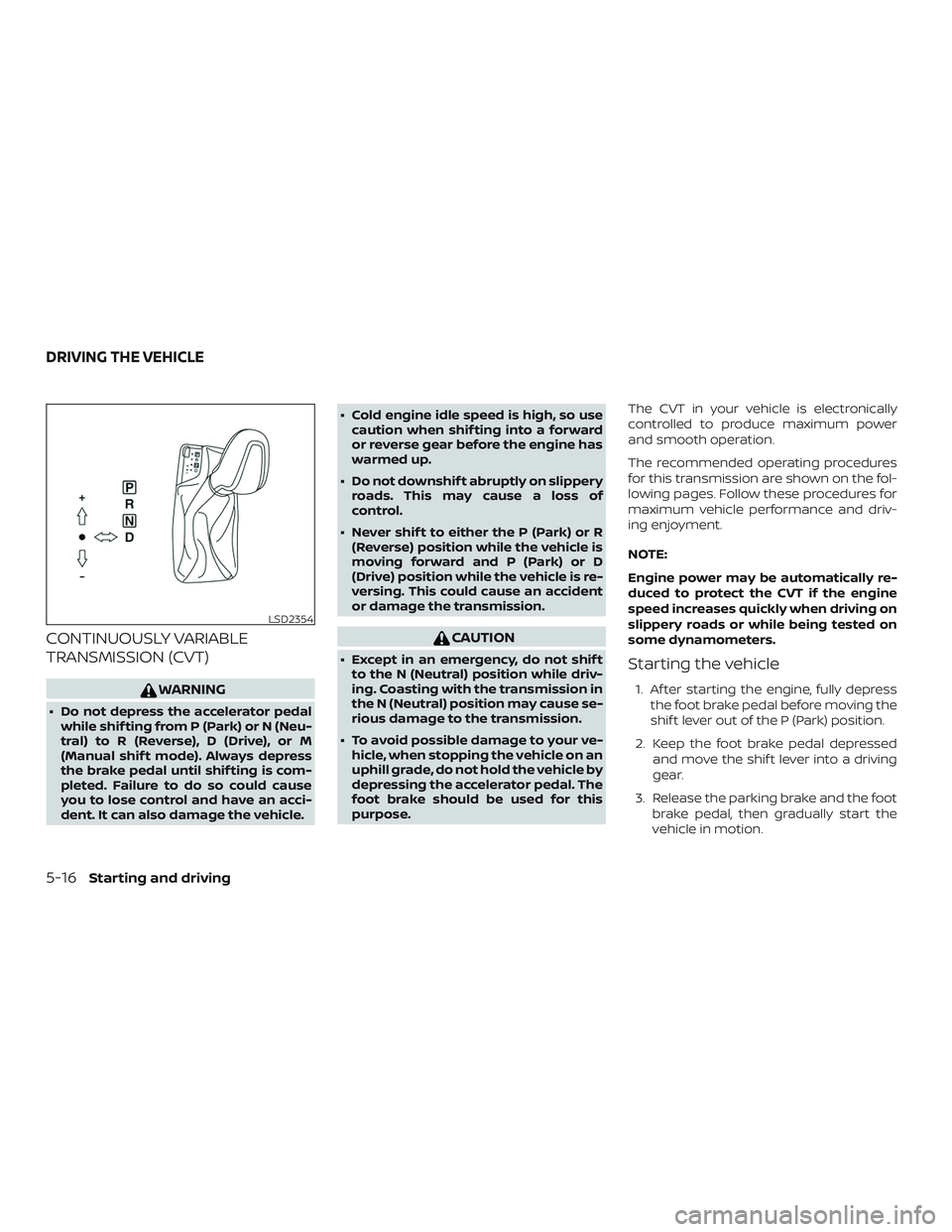
CONTINUOUSLY VARIABLE
TRANSMISSION (CVT)
WARNING
∙ Do not depress the accelerator pedalwhile shif ting from P (Park) or N (Neu-
tral) to R (Reverse), D (Drive), or M
(Manual shif t mode). Always depress
the brake pedal until shif ting is com-
pleted. Failure to do so could cause
you to lose control and have an acci-
dent. It can also damage the vehicle. ∙ Cold engine idle speed is high, so use
caution when shif ting into a forward
or reverse gear before the engine has
warmed up.
∙ Do not downshif t abruptly on slippery roads. This may cause a loss of
control.
∙ Never shif t to either the P (Park) or R (Reverse) position while the vehicle is
moving forward and P (Park) or D
(Drive) position while the vehicle is re-
versing. This could cause an accident
or damage the transmission.
CAUTION
∙ Except in an emergency, do not shif tto the N (Neutral) position while driv-
ing. Coasting with the transmission in
the N (Neutral) position may cause se-
rious damage to the transmission.
∙ To avoid possible damage to your ve- hicle, when stopping the vehicle on an
uphill grade, do not hold the vehicle by
depressing the accelerator pedal. The
foot brake should be used for this
purpose. The CVT in your vehicle is electronically
controlled to produce maximum power
and smooth operation.
The recommended operating procedures
for this transmission are shown on the fol-
lowing pages. Follow these procedures for
maximum vehicle performance and driv-
ing enjoyment.
NOTE:
Engine power may be automatically re-
duced to protect the CVT if the engine
speed increases quickly when driving on
slippery roads or while being tested on
some dynamometers.Starting the vehicle
1. Af ter starting the engine, fully depress
the foot brake pedal before moving the
shif t lever out of the P (Park) position.
2. Keep the foot brake pedal depressed and move the shif t lever into a driving
gear.
3. Release the parking brake and the foot brake pedal, then gradually start the
vehicle in motion.
LSD2354
DRIVING THE VEHICLE
5-16Starting and driving
Page 244 of 428
∙In the manual shif t mode, the trans-
mission may not shif t to the selected
gear. This helps maintain driving per-
formance and reduces the chance of
vehicle damage or loss of control.
∙ When this situation occurs, the Con-
tinuously Variable Transmission (CVT)
position indicator light will blink and
the chime will sound.
∙ In the manual shif t mode, the trans-
mission may shif t up automatically to
a higher range than selected if the
engine speed is too high. When the
vehicle speed decreases, the trans-
mission automatically shif ts down
and shif ts to 1st gear before the ve-
hicle comes to a stop.
∙ CVT operation is limited to automatic drive mode when CVT fluid tempera-
ture is extremely low even if manual
shif t mode is selected. This is not a mal-
function. When CVT fluid warms up,
manual mode can be selected.
∙ When the CVT fluid temperature is high, the shif t range may upshif t in lower
rpm than usual. This is not a malfunc-
tion.
Shif t lock release
If the battery charge is low or discharged,
the shif t lever may not be moved from the
P (Park) position even with the brake pedal
depressed and the shif t lever button
pressed.
It will be necessary to jump start or have
your battery charged. For additional infor-
mation, refer to “Jump starting” in the “In
case of emergency” section of this manual.
It is recommended that you visit a NISSAN
dealer or a professional towing service. To move the shif t lever, complete the fol-
lowing procedure:
1. Push the ignition switch to the LOCK position.
2. Apply the parking brake.
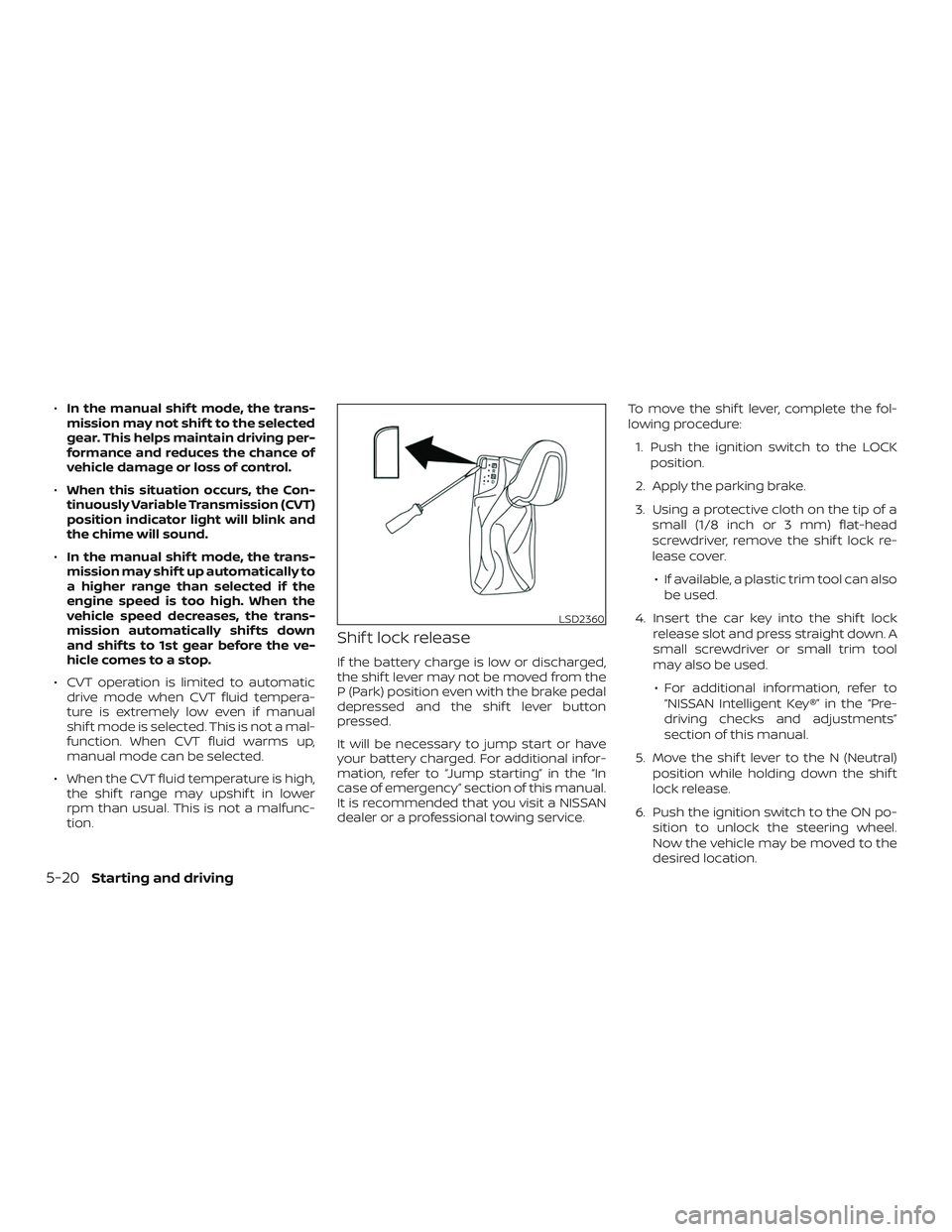
3. Using a protective cloth on the tip of a small (1/8 inch or 3 mm) flat-head
screwdriver, remove the shif t lock re-
lease cover.
∙ If available, a plastic trim tool can also be used.
4. Insert the car key into the shif t lock release slot and press straight down. A
small screwdriver or small trim tool
may also be used.
∙ For additional information, refer to “NISSAN Intelligent Key®” in the “Pre-
driving checks and adjustments”
section of this manual.
5. Move the shif t lever to the N (Neutral) position while holding down the shif t
lock release.
6. Push the ignition switch to the ON po- sition to unlock the steering wheel.
Now the vehicle may be moved to the
desired location.
LSD2360
5-20Starting and driving
Page 312 of 428
The Integrated Dynamics-control Module
is an electric control module that includes
the following functions:∙ Intelligent Trace Control
∙ Intelligent Engine Brake
∙ Active Ride Control
INTELLIGENT TRACE CONTROL
(I-TC)
This system senses driving based on the
driver’s steering and acceleration/braking
patterns, and controls brake pressure at
individual wheels to aid tracing at corners
and help smooth vehicle response.
The I–TC can be set to ON (enabled) or OFF
(disabled) through the vehicle information
display “Settings” page. For additional infor-
mation, refer to “Vehicle information dis-
play” in the “Instruments and controls” sec-
tion of this manual.
When the VDC OFF switch is used to turn off
the VDC system, the I–TC is also turned off.
If the Chassis Control System Error warn-
ing message appears in the vehicle infor-
mation display, it may indicate that the I–TC
is not functioning properly. Have the sys- tem checked as soon as possible. It is rec-
ommended that you visit a NISSAN dealer
for this service.
WARNING
The I–TC may not be effective depend-
ing on the driving condition. Always
drive carefully and attentively.
When the I–TC is operating, you may feel a
pulsation in the brake pedal and hear a
noise. This is normal and indicates that the
I–TC is operating properly.
Even if the I–TC is set to OFF, some func-
tions will remain on to assist the driver (for
example, avoidance scenes).
INTELLIGENT ENGINE BRAKE (I-EB)
The I–EB function adds subtle deceleration
by controlling the Continuously Variable
Transmission (CVT) gear ratio, depending
on the cornering condition calculated from
the driver’s steering input and plural sen-
sors. This benefit is for easier traceability
and less workload of adjusting speed with
braking at corners.
The I–EB also enhances braking feel by
adding subtle deceleration with the CVT
gear ratio control according to the driver’s
brake pedal operation. The I–EB can be set to ON (enabled) or OFF
(disabled) through the vehicle information
display “Settings” page. For additional infor-
mation, refer to “Vehicle information dis-
play” in the “Instruments and controls” sec-
tion of this manual.
If the Chassis Control System Error warn-
ing message appears in the vehicle infor-
mation display, it may indicate that the I–EB
is not functioning properly. Have the sys-
tem checked as soon as possible. It is rec-
ommended that you visit a NISSAN dealer
for this service.
WARNING
The I–EB may not be effective depend-
ing on driving conditions. Always drive
carefully and attentively.
When the I–EB is operating, the needle of
the tachometer will rise up and you may
hear an engine noise. This is normal and
indicates that the I–EB is operating prop-
erly.
INTEGRATED DYNAMICS-CONTROL
MODULE (if so equipped)
5-88Starting and driving
Page 324 of 428
4. Turn off the engine.
5. Raise the hood to warn other trafficand to signal professional road assis-
tance personnel that you need assis-
tance.
6. Have all passengers get out of the ve- hicle and stand in a safe place, away
from traffic and clear of the vehicle.
WARNING
∙ Make sure the parking brake is se-curely applied and the Continuously
Variable Transmission (CVT) is shif ted
into P (Park).
∙ Never change tires when the vehicle is on a slope, ice or slippery areas. This is
hazardous.
∙ Never change tires if oncoming traffic is close to your vehicle. Wait for pro-
fessional road assistance.
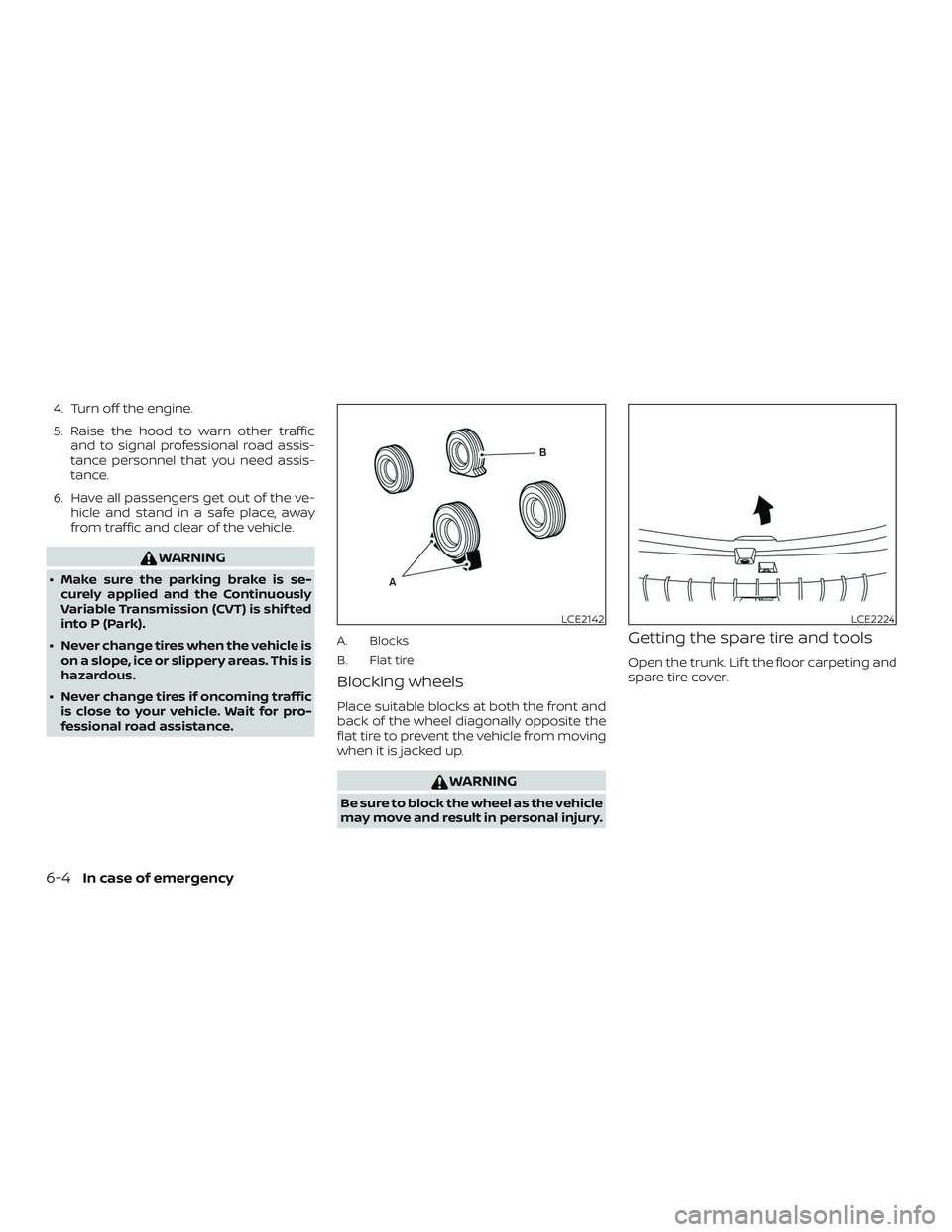
A. Blocks
B. Flat tire
Blocking wheels
Place suitable blocks at both the front and
back of the wheel diagonally opposite the
flat tire to prevent the vehicle from moving
when it is jacked up.
WARNING
Be sure to block the wheel as the vehicle
may move and result in personal injury.
Getting the spare tire and tools
Open the trunk. Lif t the floor carpeting and
spare tire cover.
LCE2142LCE2224
6-4In case of emergency
Page 330 of 428
CAUTION
∙ Continuously Variable Transmission(CVT) models cannot be push-started
or tow-started. Attempting to do so
may cause transmission damage.
∙ Do not push start this vehicle. The three-way catalyst may be damaged. If your vehicle is overheating (indicated by
an extremely high temperature gauge
reading) or if you feel a lack of engine
power, detect abnormal noise, etc., take the
following steps.
WARNING
∙ Do not continue to drive if your vehicle
overheats. Doing so could cause en-
gine damage or a vehicle fire.
∙ To avoid the danger of being scalded, never remove the radiator cap while
the engine is still hot. When the radia-
tor cap is removed, pressurized hot
water will spurt out, possibly causing
serious injury.
∙ Do not open the hood if steam is com- ing out.
1. Move the vehicle safely off the road, ap- ply the parking brake and move the
shif t lever to P (Park).
Do not stop the engine.
2. Turn off the air conditioner. Open all the windows, move the heater or air condi-
tioner temperature control to maxi-
mum hot and fan control to high
speed. 3. Get out of the vehicle. Look and listen
for steam or coolant escaping from the
radiator before opening the hood. (If
steam or coolant is escaping, turn off
the engine.) Do not open the hood fur-
ther until no steam or coolant can be
seen.
4. Open the engine hood.
WARNING
If steam or water is coming from the
engine, stand clear to prevent getting
burned.
5. Visually check drive belts for damage or looseness. Also check if the cooling
fan is running. The radiator hoses and
radiator should not leak water. If cool-
ant is leaking, the water pump belt is
missing or loose, or the cooling fan
does not run, stop the engine.
WARNING
Be careful not to allow your hands, hair,
jewelry or clothing to come into contact
with, or get caught in, engine belts or
the engine cooling fan. The engine cool-
ing fan can start at any time.
PUSH STARTING IF YOUR VEHICLE OVERHEATS
6-10In case of emergency
Page 332 of 428
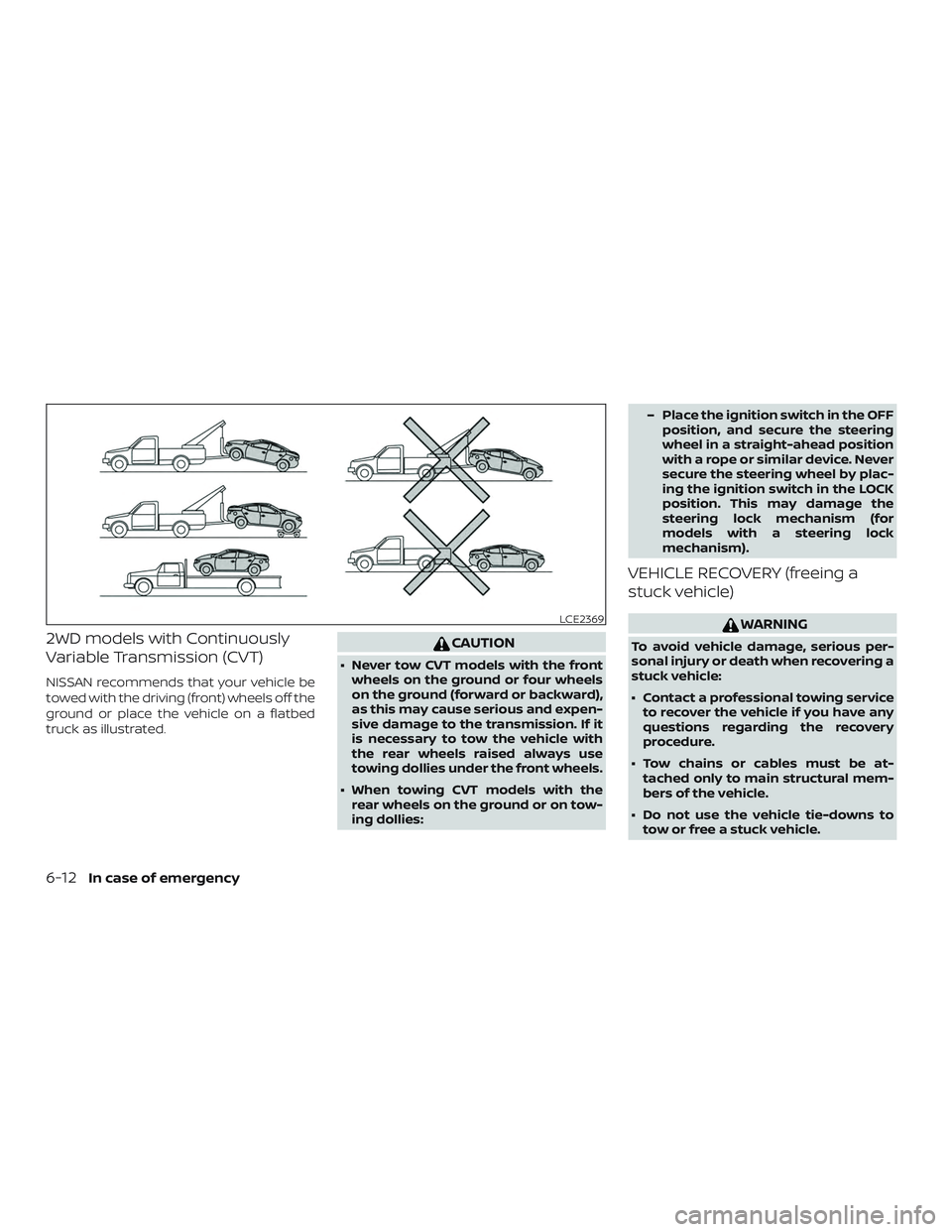
2WD models with Continuously
Variable Transmission (CVT)
NISSAN recommends that your vehicle be
towed with the driving (front) wheels off the
ground or place the vehicle on a flatbed
truck as illustrated.
CAUTION
∙ Never tow CVT models with the frontwheels on the ground or four wheels
on the ground (forward or backward),
as this may cause serious and expen-
sive damage to the transmission. If it
is necessary to tow the vehicle with
the rear wheels raised always use
towing dollies under the front wheels.
∙ When towing CVT models with the rear wheels on the ground or on tow-
ing dollies: – Place the ignition switch in the OFF
position, and secure the steering
wheel in a straight-ahead position
with a rope or similar device. Never
secure the steering wheel by plac-
ing the ignition switch in the LOCK
position. This may damage the
steering lock mechanism (for
models with a steering lock
mechanism).
VEHICLE RECOVERY (freeing a
stuck vehicle)
WARNING
To avoid vehicle damage, serious per-
sonal injury or death when recovering a
stuck vehicle:
∙ Contact a professional towing serviceto recover the vehicle if you have any
questions regarding the recovery
procedure.
∙ Tow chains or cables must be at- tached only to main structural mem-
bers of the vehicle.
∙ Do not use the vehicle tie-downs to tow or free a stuck vehicle.
LCE2369
6-12In case of emergency