parking brake NISSAN MAXIMA 2021 Owner´s Manual
[x] Cancel search | Manufacturer: NISSAN, Model Year: 2021, Model line: MAXIMA, Model: NISSAN MAXIMA 2021Pages: 476, PDF Size: 3.32 MB
Page 95 of 476

CHECKING LIGHTS
With all doors closed, apply the parking
brake, fasten the seat belts and place the
ignition switch in the ON position without
starting the engine. The following lights (if
so equipped) will come on:
,or,,,,,
The following lights (if so equipped) will
come on briefly and then go off:
or,,,,
If any light does not come on or operate in
a way other than described, it may indicate
a burned-out bulb and/or a system mal-
function. Have the system checked. It is
recommended that you visit a NISSAN
dealer for this service.
Some indicators and warnings are also dis-
played on the vehicle information display
between the speedometer and tachom-
eter. For additional information, see “Ve-
hicle information display” (P. 2-17).
WARNING/INDICATOR LIGHTS (red)
For additional information, see “Vehicle in-
formation display” (P. 2-17).
orBrake warning
light
This light functions for both the parking
brake and the foot brake systems.
Parking brake indicator
When the ignition switch is placed in the ON
position, this light comes on when the
parking brake is applied.
Low brake fluid warning light
When the ignition switch is placed in the ON
position, the light warns of a low brake fluid
level. If the light comes on while the engine
is running with the parking brake not ap-
plied, stop the vehicle and perform the
following:
1. Check the brake fluid level. Add brakefluid as necessary. For additional infor-
mation, see “Brake fluid” (P. 8-11).
2. If the brake fluid level is correct, have the warning system checked. It is recom-
mended that you visit a NISSAN dealer
for this service.
WARNING
• Your brake system may not be work-
ing properly if the warning light is on.
Driving could be dangerous. If you
judge it to be safe, drive carefully to
the nearest service station for re-
pairs. Otherwise, have your vehicle
towed because driving it could be
dangerous.
• Pressing the brake pedal with the en-
gine stopped and/or a low brake
fluid level may increase your stop-
ping distance and braking will re-
quire greater pedal effort as well as
pedal travel.
• If the brake fluid level is below the
MINIMUM or MIN mark on the brake
fluid reservoir, do not drive until the
brake system has been checked. It is
recommended that you visit a
NISSAN dealer for this service.
Instruments and controls2-9
Page 96 of 476

Charge warning light
If this light comes on while the engine is
running, it may indicate the charging sys-
tem is not functioning properly. Turn the
engine off and check the generator belt. If
the belt is loose, broken, or missing, or if the
light remains on, have the system checked.
It is recommended that you visit a NISSAN
dealer for this service.
CAUTION
Do not continue driving if the generator
belt is loose, broken or missing.
Engine oil pressure
warning light
This light warns of low engine oil pressure. If
the light flickers or comes on during nor-
mal driving, pull off the road in a safe area,
stop the engine immediatelyand call a
NISSAN dealer or other authorized repair
shop.
The engine oil pressure warning light is
not designed to indicate a low oil level.
Use the dipstick to check the oil level. For
additional information, see “Engine oil”
(P. 8-6).
CAUTION
Running the engine with the engine oil
pressure warning light on could cause
serious damage to the engine almost
immediately. Such damage is not cov-
ered by the NISSAN New Vehicle Limited
Warranty. Turn off the engine as soon
as it is safe to do so.
Master warning light
The master warning light illuminates
whenever there is an active warning that
can be reviewed in the “warnings review”
content page in the meter, or if there is a
red-level warning being displayed (which
cannot be dismissed). The master warning
light will illuminate red if a red-level warning
is being displayed, or yellow otherwise.
• Door Open (with vehicle moving)
• Parking Brake ON
• LED Headlight Failure (if no other red warnings are active)
• Shif t into Park warning
For additional information, see “Vehicle in-
formation display” (P. 2-17).
Seat belt warning light and
chime
The light and chime remind you to fasten
the driver and front passenger seat belts.
For additional information, see “Seat belts”
(P. 1-11).
Security indicator light
This light blinks when the ignition switch is
placed in the OFF, LOCK or ACC position.
The blinking security indicator light indi-
cates that the security systems equipped
on the vehicle are operational.
For additional information, see “Security
systems” (P. 2-39).
Supplemental air bag
warning light
When the ignition switch is placed in the ON
position, the supplemental air bag warning
light illuminates for about 7 seconds and
then turns off. This means the system is
operational.
2-10Instruments and controls
Page 102 of 476
Have the VDC system checked. It is recom-
mended that you visit a NISSAN dealer for
this service.
While the VDC system is operating, you
might feel a slight vibration or hear the sys-
tem working when starting the vehicle or
accelerating, but this is normal.
WARNING/INDICATOR LIGHTS
(other)
For additional information, see “Vehicle in-
formation display” (P. 2-17).
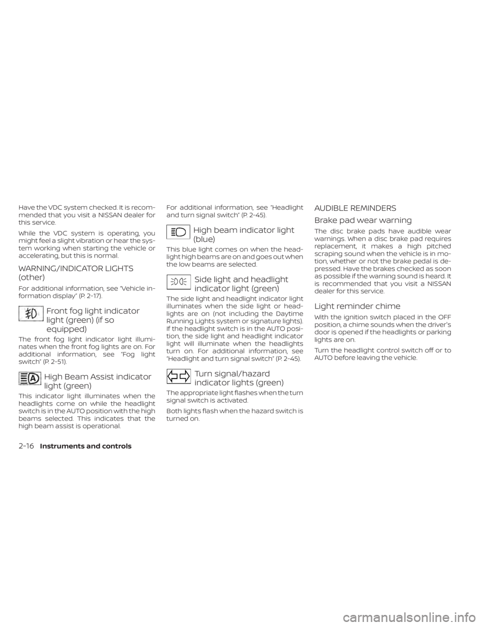
Front fog light indicator
light (green) (if so
equipped)
The front fog light indicator light illumi-
nates when the front fog lights are on. For
additional information, see “Fog light
switch” (P. 2-51).
High Beam Assist indicator
light (green)
This indicator light illuminates when the
headlights come on while the headlight
switch is in the AUTO position with the high
beams selected. This indicates that the
high beam assist is operational.For additional information, see “Headlight
and turn signal switch” (P. 2-45).
High beam indicator light
(blue)
This blue light comes on when the head-
light high beams are on and goes out when
the low beams are selected.
Side light and headlight
indicator light (green)
The side light and headlight indicator light
illuminates when the side light or head-
lights are on (not including the Daytime
Running Lights system or signature lights).
If the headlight switch is in the AUTO posi-
tion, the side light and headlight indicator
light will illuminate when the headlights
turn on. For additional information, see
“Headlight and turn signal switch” (P. 2-45).
Turn signal/hazard
indicator lights (green)
The appropriate light flashes when the turn
signal switch is activated.
Both lights flash when the hazard switch is
turned on.
AUDIBLE REMINDERS
Brake pad wear warning
The disc brake pads have audible wear
warnings. When a disc brake pad requires
replacement, it makes a high pitched
scraping sound when the vehicle is in mo-
tion, whether or not the brake pedal is de-
pressed. Have the brakes checked as soon
as possible if the warning sound is heard. It
is recommended that you visit a NISSAN
dealer for this service.
Light reminder chime
With the ignition switch placed in the OFF
position, a chime sounds when the driver's
door is opened if the headlights or parking
lights are on.
Turn the headlight control switch off or to
AUTO before leaving the vehicle.
2-16Instruments and controls
Page 106 of 476

Driver Assistance
The driver assistance menu allows the user to change the various driving aids and assistance options.
Some menu items shown below may not be equipped on your vehicle.
Menu itemExplanation
Lane Displays the available lane options. Lane Departure Warning Allows user to turn the Lane Departure Warning (LDW) system on or off. For additional information, see “Lane Departure Warning (LDW)” (P. 5-25).
Lane Departure Prevention Allows user to turn Intelligent Lane Intervention (I-LI) system on or off when the engine is running. System will reset to of f
af ter every ignition cycle. For additional information, see “Intelligent Lane Intervention (I-LI) (P. 5-30).
Blind Spot Allows user to turn the blind spot feature on or off. For additional information, see “Blind Spot Warning (BSW)” (P. 5-36) and “Rear Cross Traffic Alert (RCTA)” (P. 5-45).
Speed Limit Sign Allows user to turn the Speed Limit Sign feature on or off. For additional information, see "Traffic Sign Recognition (TSR)” (P. 5-22).
Parking Aids Displays the available parking aids. For additional information, see “Front and rear sonar system” (P. 5-116). Sensor Allows user to turn the sensor on, off, or front only.
Display Allows user to turn the display on or off.
Volume Allows user to adjust the volume to Low/Med./High.
Range Allows user to adjust the range to Near/Mid./Far.
Emergency Brake Displays the available emergency braking options. Front Allows user to turn the front emergency braking system on or off. For additional information, see “Automatic Emergency Braking (AEB) with Pedestrian Detection” (P. 5-85) and “Intelligent Forward Collision Warning (I-FCW)” (P. 5-95).
Rear Allows user to turn the rear emergency braking system on or off. For additional information, see “Rear Automatic Braking (RAB)” (P. 5-80).
Driver Attention Alert Allows user to turn the driver attention feature on or off. For additional information, see “Intelligent Driver Alertness (I- DA)”
(P. 5-106).
Timer Alert Allows user to set or reset an alert at a specific time interval.
Low Temperature Alert Allows user to turn the low temperature alert on or off.
Cruise Control Alerts Allows user to turn the Cruise Control Alerts on or off.
Chassis Control Displays the available chassis control options. For addition information, see “Integrated Dynamics-control Module” (P. 5-115). Active Trace Control Allows user to turn the Intelligent Trace Control (I-TC) on or off.
Active Engine Brake Allows user to turn the Intelligent Engine Brake (I-EB) on or off.
2-20Instruments and controls
Page 114 of 476
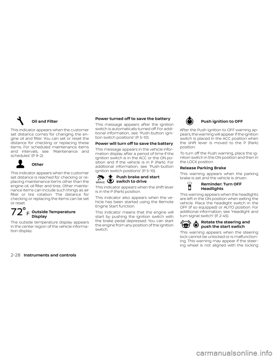
Oil and Filter
This indicator appears when the customer
set distance comes for changing the en-
gine oil and filter. You can set or reset the
distance for checking or replacing these
items. For scheduled maintenance items
and intervals, see “Maintenance and
schedules” (P. 9-2).
Other
This indicator appears when the customer
set distance is reached for checking or re-
placing maintenance items other than the
engine oil, oil filter and tires. Other mainte-
nance items can include such things as air
filter or tire rotation. The distance for
checking or replacing the items can be set
or reset.
Outside Temperature
Display
The outside temperature display appears
in the center region of the vehicle informa-
tion display.
Power turned off to save the battery
This message appears af ter the ignition
switch is automatically turned off. For addi-
tional information, see “Push-button igni-
tion switch positions” (P. 5-10).
Power will turn off to save the battery
This message appears in the vehicle infor-
mation display af ter a period of time if the
ignition switch is in the ACC or the ON po-
sition and if the vehicle is in P (Park). For
additional information, see “Push-button
ignition switch positions” (P. 5-10).
Push brake and start
switch to drive
This indicator appears when the shif t lever
is in the P (Park) position.
This indicator also appears when the ve-
hicle has been started using the Remote
Engine Start function.
This indicator means that the engine will
start by pushing the ignition switch with
the brake pedal depressed. You can start
the engine from any position of the ignition
switch.
Push ignition to OFF
Af ter the Push ignition to OFF warning ap-
pears, the warning will appear if the ignition
switch is placed in the ACC position when
the shif t lever is moved to the P (Park)
position.
To turn off the Push warning, place the ig-
nition switch in the ON position and then in
the LOCK position.
Release Parking Brake
This warning appears when the parking
brake is set and the vehicle is driven.
Reminder: Turn OFF
Headlights
This warning appears when the headlights
are lef t in the ON position when exiting the
vehicle. Place the headlight switch in the
OFF (if so equipped) or AUTO position. For
additional information, see “Headlight and
turn signal switch” (P. 2-45).
Rotate the steering and
push the start switch
This warning appears when the steering
lock cannot be unlocked or is malfunction-
ing. This warning may appear if the steer-
ing wheel is not aligned with the locking
2-28Instruments and controls
Page 136 of 476
LED DAYTIME RUNNING LIGHTS
(DRL) SYSTEM (Type A) (if so
equipped)
The LED portion of the headlights auto-
matically illuminate at 100% intensity when
the engine is started and the parking brake
released. The LED DRL operate with the
headlight switch in the OFF position. When
you turn the headlight switch to the
position for full illumination the LED lights
switch from LED DRL to the park function.
If the parking brake is applied before the
engine is started, the LED DRL do not illumi-
nate. The LED DRL illuminate when the
parking brake is released. The LED DRL re-
main on while the engine is running.
It is necessary at dusk to turn the headlight
switch on for interior controls and switches
to illuminate, as those remain off while the
switch is in the OFF position.
WARNING
When the LED DRL system is active, tail
lights on your vehicle are not on. It is
necessary at dusk to turn on your
headlights. Failure to do so could cause
an accident injuring yourself and others.
LED DAYTIME RUNNING LIGHTS
(DRL) SYSTEM (Type B) (if so
equipped)
The LED DRL automatically illuminate at
100% intensity when the engine is started
and the parking brake released. The LED
Daytime Running Lights (DRL) operate with
the headlight switch in any position. When
you turn the headlight switch to the
position for full illumination, the LED DRL
illuminate at a lower intensity.
If the parking brake is applied before the
engine is started, the LED DRL do not illumi-
nate. The LED DRL illuminate when the
parking brake is released. The LED DRL will
remain on until the ignition switch is placed
in the OFF position.
At dusk, the headlights, interior controls
and switches will automatically illuminate if
the headlight switch is in the AUTO position.
WARNING
When the LED DRL system is active, tail
lights on your vehicle are not on. It is
necessary at dusk to turn on your
headlights. Failure to do so could cause
an accident injuring yourself and others.
INSTRUMENT BRIGHTNESS
CONTROL
Press the “+” button to increase the bright-
ness of instrument panel lights.
Press the “-” button to decrease the bright-
ness of instrument panel lights.
LIC3176
2-50Instruments and controls
Page 183 of 476

The following events will occur when the
engine starts:
• The parking lights will turn on and remainon as long as the engine is running.
• The doors will be locked and the climate control system may come on.
• The engine will continue to run for 10 min- utes. Repeat the steps to extend the time
for an additional 10 minutes. For addi-
tional information, see “Extending engine
run time” (P. 3-19).
Press and hold the brake pedal while
switching the ignition to the ON position
before driving. For additional information,
see “Driving the vehicle” (P. 5-16).
EXTENDING ENGINE RUN TIME
The Remote Engine Start feature can be
extended one time by performing the
steps listed in “Remote starting the vehicle”
in this section. Run time will be calculated
as follows:
• The first 10 minute run time will start when the Remote Engine Start function is
performed. • The second 10 minutes will start immedi-
ately when the Remote Engine Start
function is performed again. For example,
if the engine has been running for 5 min-
utes, and 10 minutes are added, the en-
gine will run for a total of 15 minutes.
• Extending engine run time will bring you to the two Remote Engine Start limit.
A maximum of two Remote Engine Starts,
or a single Remote Engine Start with an
extension, are allowed between ignition
cycles. The ignition switch must be cycled
to the ON position and then back to the
OFF position before the Remote Engine
Start procedure can be used again.
CANCELING A REMOTE ENGINE
START
To cancel a Remote Engine Start, perform
one of the following:
• Aim the Intelligent Key at the vehicle and press
until the parking lights turn off.
• Turn on the hazard warning flashers.
• Cycle the ignition switch on and then off.
• The extended engine run time has expired.
• The first 10 minute timer has expired.
• Opening the engine hood.
• Shif ting the vehicle out of P (Park). • The alarm sounds due to illegal entry into
the vehicle.
• Pushing the ignition switch without the Intelligent Key in the vehicle.
• Not pressing the brake pedal while press- ing the ignition switch with the Intelligent
Key in the vehicle.
CONDITIONS THE REMOTE ENGINE
START WILL NOT WORK
The Remote Engine Start will not operate if
any of the following conditions are present:
• The ignition switch is placed in the ONposition.
• The hood is not securely closed.
• The hazard indicator lights are on.
• The engine is still running. The engine must be completely stopped. Wait at
least 6 seconds if the engine goes from
running to off. This is not applicable when
extending engine run time.
• The
button is not pressed and held
for at least 2 seconds.
• The
button is not pressed and held
within 5 seconds of pressing the lock
button.
• The brake is pressed.
• The doors are not closed and locked.
Pre-driving checks and adjustments3-19
Page 203 of 476
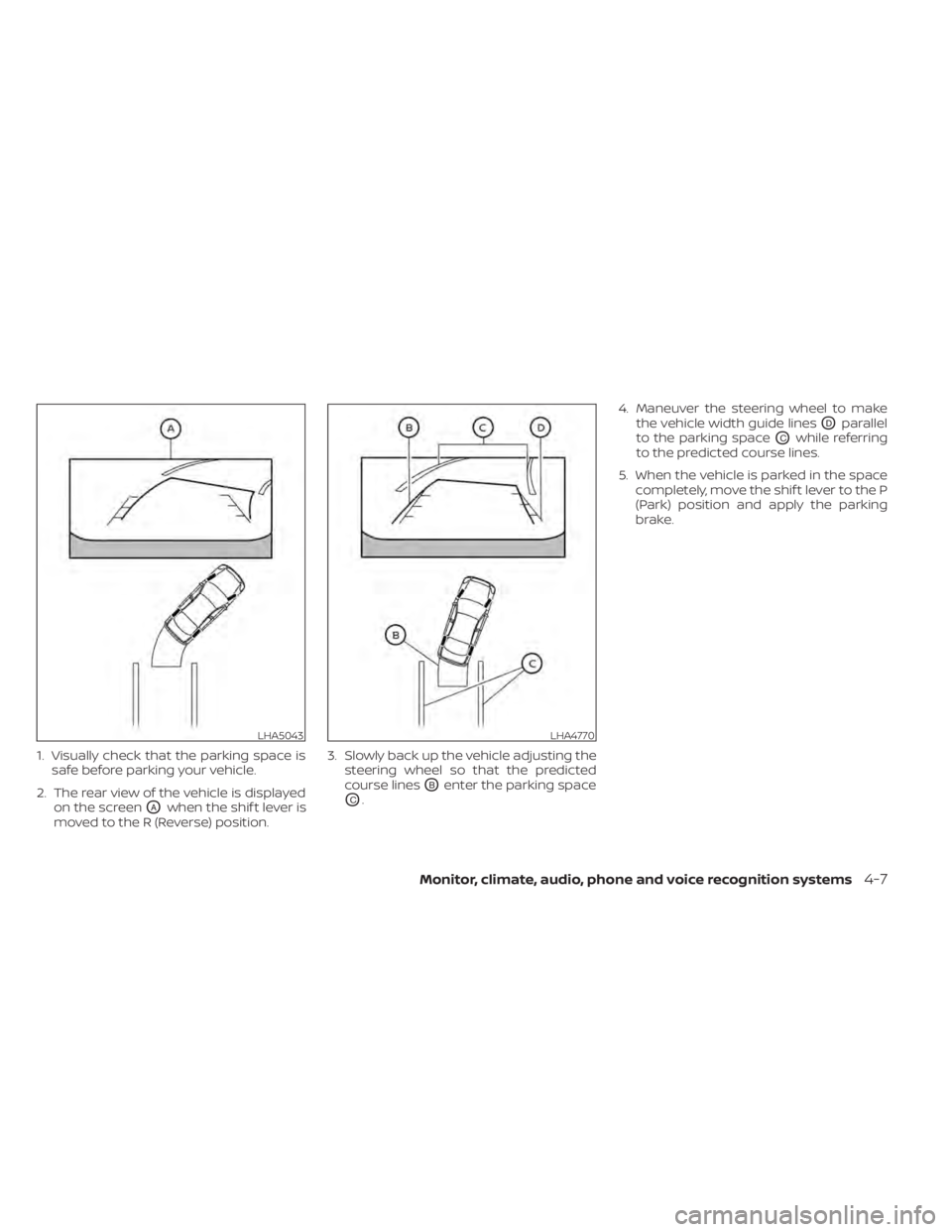
1. Visually check that the parking space issafe before parking your vehicle.
2. The rear view of the vehicle is displayed on the screen
OAwhen the shif t lever is
moved to the R (Reverse) position. 3. Slowly back up the vehicle adjusting the
steering wheel so that the predicted
course lines
OBenter the parking space
OC. 4. Maneuver the steering wheel to make
the vehicle width guide lines
ODparallel
to the parking space
OCwhile referring
to the predicted course lines.
5. When the vehicle is parked in the space completely, move the shif t lever to the P
(Park) position and apply the parking
brake.
LHA5043LHA4770
Monitor, climate, audio, phone and voice recognition systems4-7
Page 204 of 476
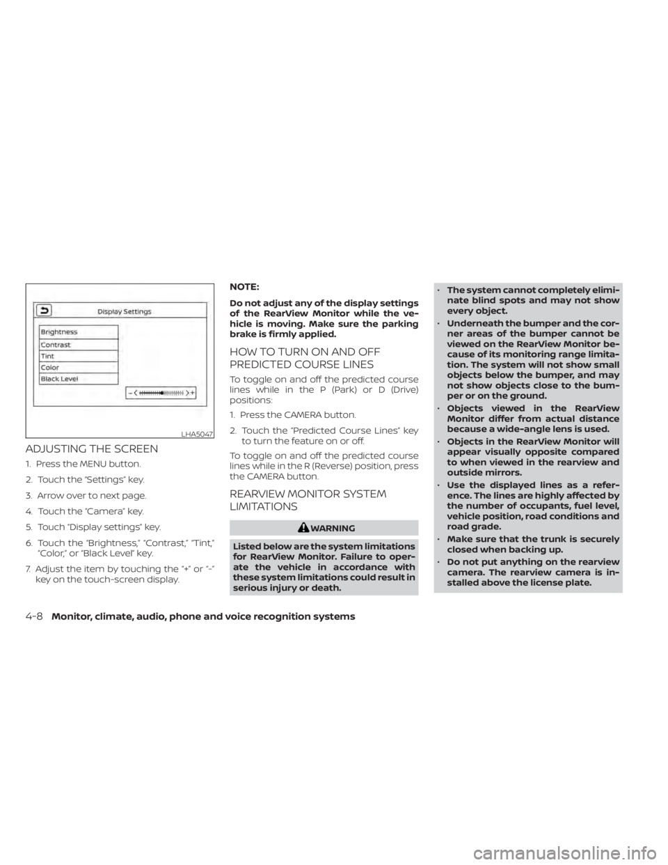
ADJUSTING THE SCREEN
1. Press the MENU button.
2. Touch the “Settings” key.
3. Arrow over to next page.
4. Touch the “Camera” key.
5. Touch “Display settings” key.
6. Touch the “Brightness,” “Contrast,” “Tint,”“Color,” or “Black Level” key.
7. Adjust the item by touching the “+” or “-” key on the touch-screen display.
NOTE:
Do not adjust any of the display settings
of the RearView Monitor while the ve-
hicle is moving. Make sure the parking
brake is firmly applied.
HOW TO TURN ON AND OFF
PREDICTED COURSE LINES
To toggle on and off the predicted course
lines while in the P (Park) or D (Drive)
positions:
1. Press the CAMERA button.
2. Touch the “Predicted Course Lines” key to turn the feature on or off.
To toggle on and off the predicted course
lines while in the R (Reverse) position, press
the CAMERA button.
REARVIEW MONITOR SYSTEM
LIMITATIONS
WARNING
Listed below are the system limitations
for RearView Monitor. Failure to oper-
ate the vehicle in accordance with
these system limitations could result in
serious injury or death. •
The system cannot completely elimi-
nate blind spots and may not show
every object.
• Underneath the bumper and the cor-
ner areas of the bumper cannot be
viewed on the RearView Monitor be-
cause of its monitoring range limita-
tion. The system will not show small
objects below the bumper, and may
not show objects close to the bum-
per or on the ground.
• Objects viewed in the RearView
Monitor differ from actual distance
because a wide-angle lens is used.
• Objects in the RearView Monitor will
appear visually opposite compared
to when viewed in the rearview and
outside mirrors.
• Use the displayed lines as a refer-
ence. The lines are highly affected by
the number of occupants, fuel level,
vehicle position, road conditions and
road grade.
• Make sure that the trunk is securely
closed when backing up.
• Do not put anything on the rearview
camera. The rearview camera is in-
stalled above the license plate.
LHA5047
4-8Monitor, climate, audio, phone and voice recognition systems
Page 214 of 476
4. Maneuver the steering wheel to makethe vehicle width guide lines
ODparallel
to the parking space
OCwhile referring
to the predicted course lines.
5. When the vehicle is parked in the space completely, move the shif t lever to the P
(Park) position and apply the parking
brake.
HOW TO SWITCH THE DISPLAY
With the ignition switch in the ON position,
press the CAMERA button or move the shif t
lever to the R (Reverse) position to operate
the Intelligent Around View Monitor.
The Intelligent Around View Monitor dis-
plays different split screen views depend-
ing on the position of the shif t lever. Press
the CAMERA button to switch between the
available views.
If the shif t lever is in the R (Reverse) position,
the available views are:
• Rear view/bird’s-eye view split screen
• Rear view/front-side view split screen
• Rear-wide view If the shif t lever is in the P (Park) or D (Drive)
position, the available views are:
• Front view/bird’s-eye view split screen
• Front view/front-side view split screen
The display will switch from the Intelligent
Around View Monitor screen when:
• The shif t lever is in the D (Drive) position
and the vehicle speed increases above
approximately 5 mph (8 km/h)
• A different screen is selected.
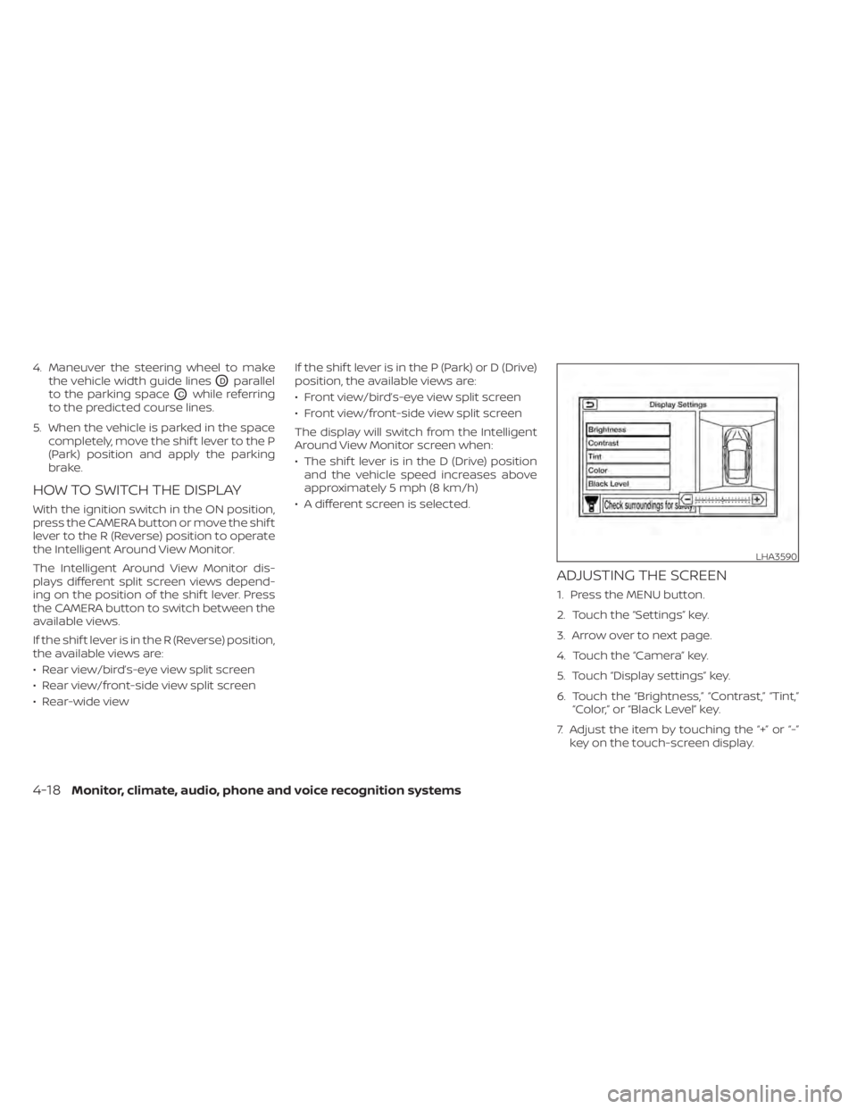
ADJUSTING THE SCREEN
1. Press the MENU button.
2. Touch the “Settings” key.
3. Arrow over to next page.
4. Touch the “Camera” key.
5. Touch “Display settings” key.
6. Touch the “Brightness,” “Contrast,” “Tint,” “Color,” or “Black Level” key.
7. Adjust the item by touching the “+” or “-” key on the touch-screen display.
LHA3590
4-18Monitor, climate, audio, phone and voice recognition systems