ESP NISSAN MAXIMA 2023 User Guide
[x] Cancel search | Manufacturer: NISSAN, Model Year: 2023, Model line: MAXIMA, Model: NISSAN MAXIMA 2023Pages: 494, PDF Size: 5.7 MB
Page 174 of 494
CHILD SAFETY REAR DOOR LOCK
Child safety locks help prevent the rear
doors from being opened accidentally,
especially when small children are in the
vehicle.
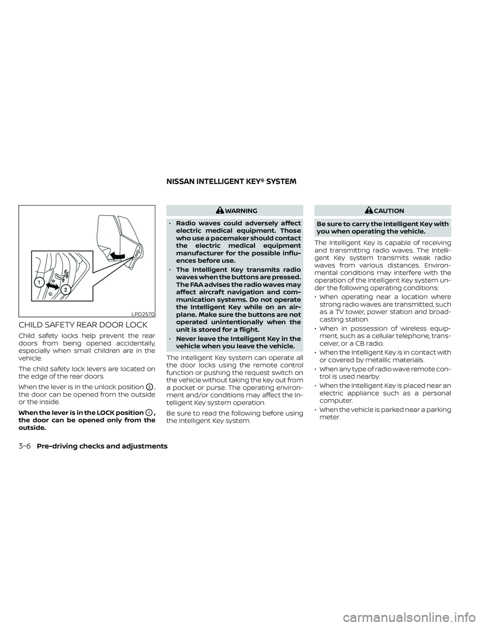
The child safety lock levers are located on
the edge of the rear doors.
When the lever is in the unlock position
O2,
the door can be opened from the outside
or the inside.
When the lever is in the LOCK position
O1,
the door can be opened only from the
outside.
WARNING
• Radio waves could adversely affect
electric medical equipment. Those
who use a pacemaker should contact
the electric medical equipment
manufacturer for the possible influ-
ences before use.
• The Intelligent Key transmits radio
waves when the buttons are pressed.
The FAA advises the radio waves may
affect aircraf t navigation and com-
munication systems. Do not operate
the Intelligent Key while on an air-
plane. Make sure the buttons are not
operated unintentionally when the
unit is stored for a flight.
• Never leave the Intelligent Key in the
vehicle when you leave the vehicle.
The Intelligent Key system can operate all
the door locks using the remote control
function or pushing the request switch on
the vehicle without taking the key out from
a pocket or purse. The operating environ-
ment and/or conditions may affect the In-
telligent Key system operation.
Be sure to read the following before using
the Intelligent Key system.CAUTION
Be sure to carry the Intelligent Key with
you when operating the vehicle.
The Intelligent Key is capable of receiving
and transmitting radio waves. The Intelli-
gent Key system transmits weak radio
waves from various distances. Environ-
mental conditions may interfere with the
operation of the Intelligent Key system un-
der the following operating conditions:
• When operating near a location where strong radio waves are transmitted, such
as a TV tower, power station and broad-
casting station.
• When in possession of wireless equip- ment, such as a cellular telephone, trans-
ceiver, or a CB radio.
• When the Intelligent Key is in contact with or covered by metallic materials.
• When any type of radio wave remote con- trol is used nearby.
• When the Intelligent Key is placed near an electric appliance such as a personal
computer.
• When the vehicle is parked near a parking meter.
LPD2570
NISSAN INTELLIGENT KEY® SYSTEM
3-6Pre-driving checks and adjustments
Page 183 of 494
WARNING SIGNALS
To help prevent the vehicle from moving
unexpectedly by erroneous operation of
the Intelligent Key or to help prevent the
vehicle from being stolen, a chime or
buzzer sounds from inside and outside the
vehicle and a warning is displayed in the
instrument panel.When a chime or beep sounds or a warning
is displayed, be sure to check the vehicle
and the Intelligent Key.
For additional information, see “Trouble-
shooting guide” (P. 3-15) and “Vehicle infor-
mation display” (P. 2-17).
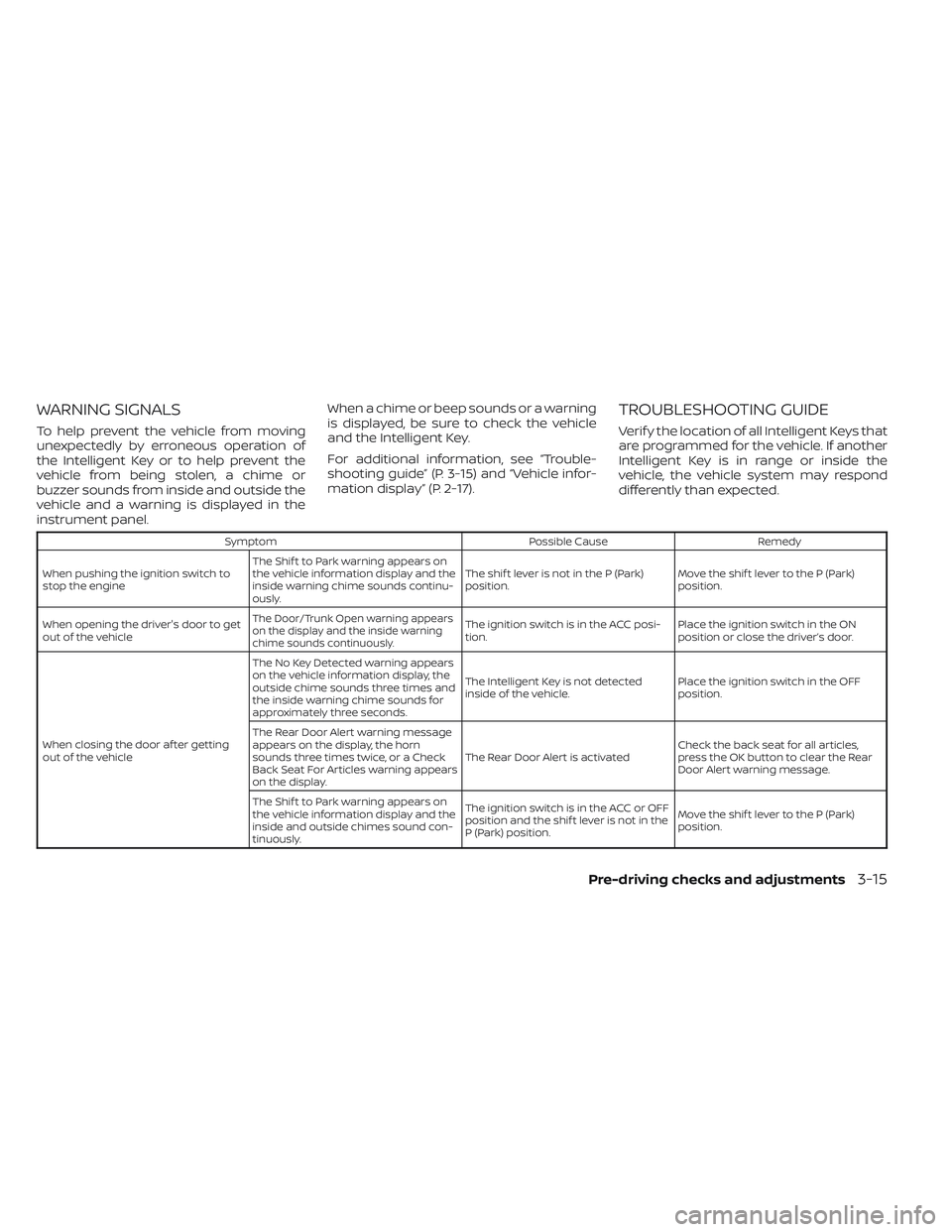
TROUBLESHOOTING GUIDE
Verif y the location of all Intelligent Keys that
are programmed for the vehicle. If another
Intelligent Key is in range or inside the
vehicle, the vehicle system may respond
differently than expected.
Symptom
Possible CauseRemedy
When pushing the ignition switch to
stop the engine The Shif t to Park warning appears on
the vehicle information display and the
inside warning chime sounds continu-
ously. The shif t lever is not in the P (Park)
position.
Move the shif t lever to the P (Park)
position.
When opening the driver's door to get
out of the vehicle
The Door/Trunk Open warning appears
on the display and the inside warning
chime sounds continuously.The ignition switch is in the ACC posi-
tion. Place the ignition switch in the ON
position or close the driver’s door.
When closing the door af ter getting
out of the vehicle The No Key Detected warning appears
on the vehicle information display, the
outside chime sounds three times and
the inside warning chime sounds for
approximately three seconds.
The Intelligent Key is not detected
inside of the vehicle.
Place the ignition switch in the OFF
position.
The Rear Door Alert warning message
appears on the display, the horn
sounds three times twice, or a Check
Back Seat For Articles warning appears
on the display. The Rear Door Alert is activated
Check the back seat for all articles,
press the OK button to clear the Rear
Door Alert warning message.
The Shif t to Park warning appears on
the vehicle information display and the
inside and outside chimes sound con-
tinuously. The ignition switch is in the ACC or OFF
position and the shif t lever is not in the
P (Park) position.
Move the shif t lever to the P (Park)
position.
Pre-driving checks and adjustments3-15
Page 198 of 494
The outside mirror surfaces will return to
their original position when one of the fol-
lowing has occurred:
• The shif t lever is moved to any positionother than R (Reverse).
• The outside mirror control switch is set to the neutral or center position.
• The ignition switch is placed in the OFF position.
NOTE:
If the outside mirror control switch is in
the center (neutral) position, mirror sur-
face will NOT turn downward when the
shif t lever is moved to R (Reverse).
For additional information regarding this
feature, see “Memory seat” (P. 3-30).
The memory seat system has three features:
• Memory storage function (Key-link)
• Memory storage function (Switch)
• Entry/exit function
Key-link, when enabled, automatically re-
tains the driver’s last seat, automatic steer-
ing wheel, and outside mirror positions for
that specific key when the ignition is posi-
tioned from ON to OFF.
Each memory switch button (1 or 2) on the
driver’s door can also store one additional
position which is independent of the key-
linked position.
MEMORY STORAGE FUNCTION
(key-link)
Use the following process to setup key-link:
1. Unlock the vehicle with the desired Intel- ligent Key while the ignition is OFF.
2. Place the ignition in the ON position.
3. Within the “Settings” menu of the vehicle information display, select “Key-Linked
Settings” and press the OK button on the
steering switch.
4. While in the menu, press the OK button on the steering switch to turn the sys-
tem ON/OFF. Once step 4 is completed, every time the
ignition is switched from ON to OFF, the
memory positions of the driver’s seat, au-
tomatic steering wheel and the outside
mirrors are linked to the Intelligent Key.
Follow the same procedure if you want
to link the 2nd, 3rd or 4th Intelligent Key.
NOTE:
If new memory positions are set prior to
turning the ignition from ON to OFF, the
previously linked memory positions for
the respective key will be overwritten by
new positions.
Recalling Intelligent Key memory
positions
If the “Key-Linked Settings” are enabled in
the vehicle information display for that par-
ticular key, every time you enter the vehicle
the driver’s seat, automatic steering wheel,
and outside mirrors will automatically
move to the driver’s last position of the
respective Intelligent Key.
NOTE:
The key-linked memory positions can be
different from the positions stored in the
memory switch (1 or 2).
MEMORY SEAT (if so equipped)
3-30Pre-driving checks and adjustments
Page 199 of 494
MEMORY STORAGE FUNCTION
(switch)
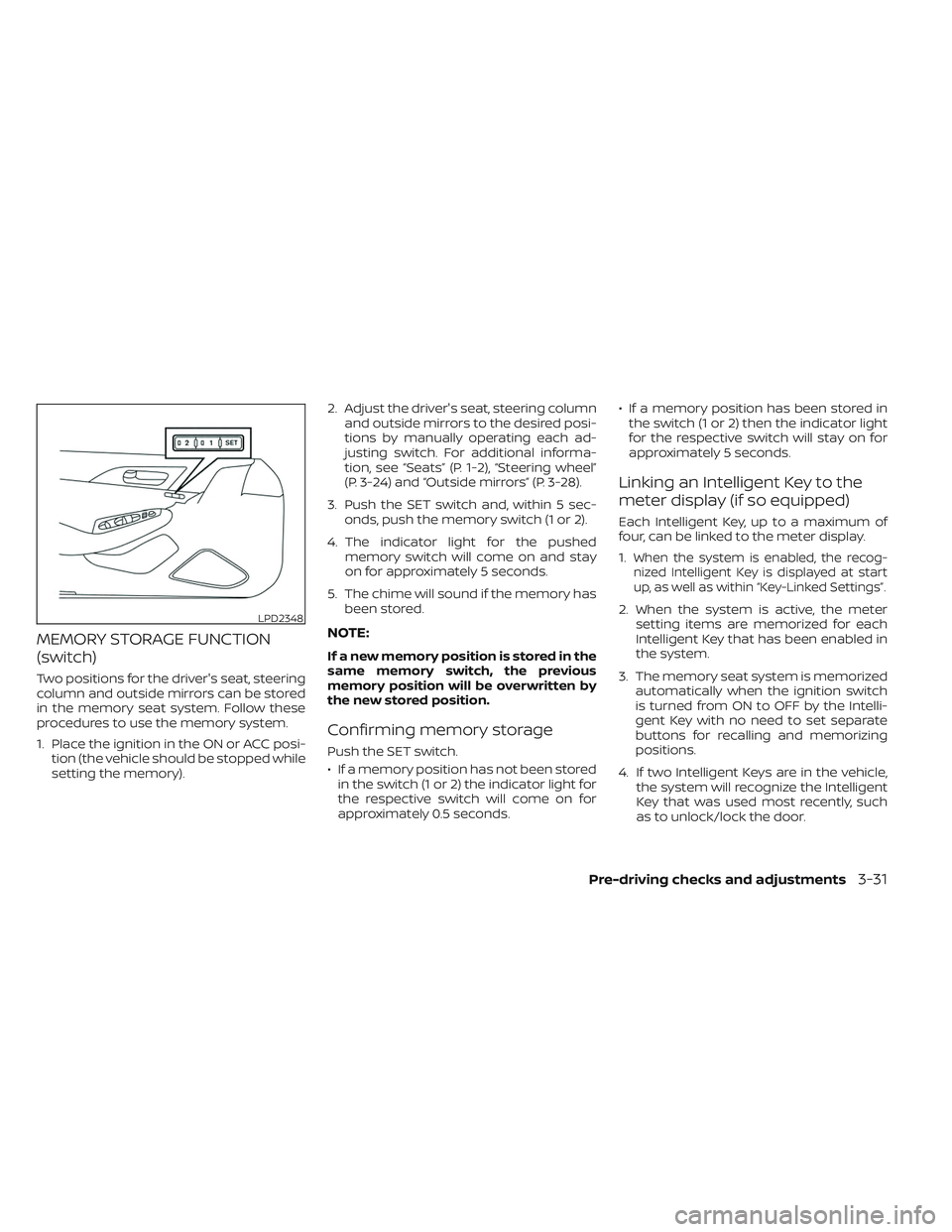
Two positions for the driver's seat, steering
column and outside mirrors can be stored
in the memory seat system. Follow these
procedures to use the memory system.
1. Place the ignition in the ON or ACC posi-tion (the vehicle should be stopped while
setting the memory). 2. Adjust the driver's seat, steering column
and outside mirrors to the desired posi-
tions by manually operating each ad-
justing switch. For additional informa-
tion, see “Seats” (P. 1-2), “Steering wheel”
(P. 3-24) and “Outside mirrors” (P. 3-28).
3. Push the SET switch and, within 5 sec- onds, push the memory switch (1 or 2).
4. The indicator light for the pushed memory switch will come on and stay
on for approximately 5 seconds.
5. The chime will sound if the memory has been stored.
NOTE:
If a new memory position is stored in the
same memory switch, the previous
memory position will be overwritten by
the new stored position.
Confirming memory storage
Push the SET switch.
• If a memory position has not been storedin the switch (1 or 2) the indicator light for
the respective switch will come on for
approximately 0.5 seconds. • If a memory position has been stored in
the switch (1 or 2) then the indicator light
for the respective switch will stay on for
approximately 5 seconds.
Linking an Intelligent Key to the
meter display (if so equipped)
Each Intelligent Key, up to a maximum of
four, can be linked to the meter display.
1.
When the system is enabled, the recog-
nized Intelligent Key is displayed at start
up, as well as within “Key-Linked Settings”.
2. When the system is active, the meter setting items are memorized for each
Intelligent Key that has been enabled in
the system.
3. The memory seat system is memorized automatically when the ignition switch
is turned from ON to OFF by the Intelli-
gent Key with no need to set separate
buttons for recalling and memorizing
positions.
4. If two Intelligent Keys are in the vehicle, the system will recognize the Intelligent
Key that was used most recently, such
as to unlock/lock the door.LPD2348
Pre-driving checks and adjustments3-31
Page 212 of 494
WARNING
• Failure to follow the warnings and in-
structions for the proper use of the
Intelligent Around View® Monitor
system could result in serious injury
or death.
• The Intelligent Around View® Monitor
is a convenience feature and is not a
substitute for proper vehicle opera-
tion because it has areas where ob-
jects cannot be viewed. The four cor-
ners of the vehicle in particular, are
areas where objects do not always
appear in the bird’s-eye, front, or rear
views. Always check your surround-
ings to be sure that it is safe to move
before operating the vehicle. Always
operate the vehicle slowly.
• The driver is always responsible for
safety during parking and other
maneuvers.
CAUTION
Do not scratch the camera lens when
cleaning dirt or snow from the front of
the camera. The Intelligent Around View® Monitor sys-
tem is designed as an aid to the driver in
situations such as slot parking or parallel
parking.
The monitor displays various views of the
position of the vehicle in a split screen for-
mat. Not all views are available at all times.
Available views:
• Front View
An approximately 150–degree view of the
front of the vehicle.
• Rear View An approximately 150–degree view of the
rear of the vehicle.
• Bird's-Eye View The surrounding views of the vehicle
from above.
• Front-Side View The view around and ahead of the front
passenger's side wheel.
• Rear-Wide View An approximately 180–degree view of the
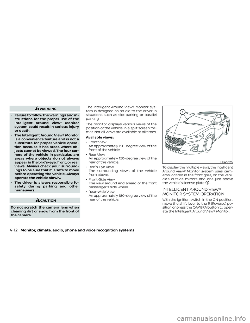
rear of the vehicle. To display the multiple views, the Intelligent
Around View® Monitor system uses cam-
eras located in the front grille, on the vehi-
cle’s outside mirrors and one just above
the vehicle’s license plate
O1.
INTELLIGENT AROUND VIEW®
MONITOR SYSTEM OPERATION
With the ignition switch in the ON position,
move the shif t lever to the R (Reverse) po-
sition or press the CAMERA button to oper-
ate the Intelligent Around View® Monitor.
LHA5026
4-12Monitor, climate, audio, phone and voice recognition systems
Page 234 of 494
When installing a CB, ham radio or car
phone in your vehicle, be sure to observe
the following precautions; otherwise, the
new equipment may adversely affect the
engine control system and other electronic
parts.
WARNING
• A cellular phone should not be used
for any purpose while driving so full
attention may be given to vehicle
operation. Some jurisdictions pro-
hibit the use of cellular phones while
driving.
• If you must make a call while your
vehicle is in motion, the hands free
cellular phone operational mode
(if so equipped) is highly recom-
mended. Exercise extreme caution at
all times so full attention may be
given to vehicle operation.
• If you are unable to devote full atten-
tion to vehicle operation while talk-
ing on the phone, pull off the road to
a safe location and stop your vehicle.
CAUTION
• Keep the antenna as far away as pos-
sible from the electronic control
modules.
• Keep the antenna wire more than 8 in
(20 cm) away from the electronic
control system harnesses. Do not
route the antenna wire next to any
harness.
• Adjust the antenna standing-wave
ratio as recommended by the
manufacturer.
• Connect the ground wire from the CB
radio chassis to the body.
• For additional information, it is rec-
ommended that you visit a NISSAN
dealer. “Made for iPod”, “Made for iPhone” and
“Made for iPad” mean that an electronic
accessory has been designed to connect
specifically to iPod, iPhone or iPad, respec-
tively, and has been certified by the devel-
oper to meet Apple performance stan-
dards. Apple is not responsible for the
operation of this device or its compliance
with safety and regulatory standards.
Please note that the use of this accessory
with iPod, iPhone or iPad may affect wire-
less performance.
iPad, iPhone, iPod classic, iPod nano, iPod
shuffle and iPod touch are trademarks of
Apple Inc., registered in the U.S. and other
countries. Lightning is a trademark of
Apple Inc.
CAR PHONE OR CB RADIO
iPod®/iPhone®
4-34Monitor, climate, audio, phone and voice recognition systems
Page 239 of 494
•Do not stop or park the vehicle over
flammable materials such as dry
grass, waste paper or rags. They may
ignite and cause a fire.
CAUTION
• Do not use leaded gasoline. Deposits
from leaded gasoline will seriously
reduce the three-way catalyst's abil-
ity to help reduce exhaust pollutants.
• Keep your engine tuned up. Malfunc-
tions in the ignition, fuel injection, or
electrical systems can cause overrich
fuel flow into the three-way catalyst,
causing it to overheat. Do not keep
driving if the engine misfires, or if
noticeable loss of performance or
other unusual operating conditions
are detected. Have the vehicle in-
spected promptly. It is recom-
mended that you visit a NISSAN
dealer for this service.
• Avoid driving with an extremely low
fuel level. Running out of fuel could
cause the engine to misfire, damag-
ing the three-way catalyst.
• Do not race the engine while warm-
ing it up. •
Do not push or tow your vehicle to
start the engine.
TIRE PRESSURE MONITORING
SYSTEM (TPMS)
Each tire, including the spare (if provided),
should be checked monthly when cold and
inflated to the inflation pressure recom-
mended by the vehicle manufacturer on
the vehicle placard or tire inflation pressure
label. (If your vehicle has tires of a different
size than the size indicated on the vehicle
placard or tire inflation pressure label, you
should determine the proper tire inflation
pressure for those tires.)
As an added safety feature, your vehicle
has been equipped with a Tire Pressure
Monitoring System (TPMS) that illuminates
a low tire pressure telltale when one or
more of your tires is significantly under-
inflated. Accordingly, when the low tire
pressure telltale illuminates, you should
stop and check all your tires as soon as
possible, and inflate them to the proper
pressure. Driving on a significantly under-
inflated tire causes the tire to overheat and
can lead to tire failure. Under-inflation also
reduces fuel efficiency and tire tread life,
and may affect the vehicle’s handling and
stopping ability. Please note that the TPMS is not a substi-
tute for proper tire maintenance, and it is
the driver’s responsibility to maintain cor-
rect tire pressure, even if under-inflation
has not reached the level to trigger illumi-
nation of the TPMS low tire pressure telltale.
Your vehicle has also been equipped with a
TPMS malfunction indicator to indicate
when the system is not operating properly.
The TPMS malfunction indicator is com-
bined with the low tire pressure telltale.
When the system detects a malfunction,
the telltale will flash for approximately one
minute and then remain continuously illu-
minated. This sequence will continue upon
subsequent vehicle start-ups as long as
the malfunction exists. When the malfunc-
tion indicator is illuminated, the system
may not be able to detect or signal low tire
pressure as intended. TPMS malfunctions
may occur for a variety of reasons, includ-
ing the installation of replacement or alter-
nate tires or wheels on the vehicle that
prevent the TPMS from functioning prop-
erly. Always check the TPMS malfunction
telltale af ter replacing one or more tires or
wheels on your vehicle to ensure that the
replacement or alternate tires and wheels
allow the TPMS to continue to function
properly.
Starting and driving5-5
Page 241 of 494
•When using a wheel without the
TPMS such as the spare tire, when a
spare tire is mounted or a wheel is
replaced, tire pressure will not be in-
dicated, the TPMS will not function
and the low tire pressure warning
light will flash for approximately 1
minute. The light will remain on af ter
1 minute. Have your tires replaced
and/or TPMS system reset as soon as
possible. It is recommended that you
visit a NISSAN dealer for this service.
•
Replacing tires with those not origi-
nally specified by NISSAN could affect
the proper operation of the TPMS.
• Do not inject any tire liquid or aerosol
tire sealant into the tires, as this may
cause a malfunction of the tire pres-
sure sensors.
CAUTION
Do not place metalized film or any
metal parts (antenna, etc.) on the win-
dows. This may cause poor reception
of the signals from the tire pressure
sensors, and the TPMS will not function
properly. Some devices and transmitters may tem-
porarily interfere with the operation of the
TPMS and cause the low tire pressure
warning light to illuminate.
Some examples are:
• Facilities or electric devices using similar
radio frequencies are near the vehicle.
• If a transmitter set to similar frequencies is being used in or near the vehicle.
• If a computer (or similar equipment) or a DC/AC converter is being used in or near
the vehicle.
The low tire pressure warning light may
illuminate in the following cases:
• If the vehicle is equipped with a wheel and tire without TPMS
• If the TPMS has been replaced and the ID has not been registered
• If the wheel is not originally specified by NISSAN
FCC Notice:
For USA:
This device complies with Part 15 of the
FCC Rules. Operation is subject to the fol-
lowing two conditions: (1) This device
may not cause harmful interference, and (2) this device must accept any interfer-
ence received, including interference
that may cause undesired operation.
NOTE:Changes or modifications not expressly
approved by the party responsible for
compliance could void the user's au-
thority to operate the equipment.
For Canada:
This device contains licence-exempt
transmitter(s)/receiver(s) that comply
with Innovation, Science and Economic
Development Canada’s licence-exempt
RSS(s). Operation is subject to the fol-
lowing two conditions: (1) This device
may not cause interference. (2) This de-
vice must accept any interference, in-
cluding interference that may cause un-
desired operation of the device.
TPMS with Easy-Fill Tire Alert
When adding air to an under-inflated tire,
the TPMS with Easy-Fill Tire Alert provides
visual and audible signals outside the
vehicle to help you inflate the tires to the
recommended COLD tire pressure.
Starting and driving5-7
Page 243 of 494
OFF-ROAD RECOVERY
While driving, the right side or lef t side
wheels may unintentionally leave the road
surface. If this occurs, maintain control of
the vehicle by following the procedure be-
low. Please note that this procedure is only
a general guide. The vehicle must be driven
as appropriate based on the conditions of
the vehicle, road and traffic.
1. Remain calm and do not overreact.
2. Do not apply the brakes.
3. Maintain a firm grip on the steeringwheel with both hands and try to hold a
straight course.
4. When appropriate, slowly release the accelerator pedal to gradually slow the
vehicle.
5. If there is nothing in the way, steer the vehicle to follow the road while vehicle
speed is reduced. Do not attempt to
drive the vehicle back onto the road sur-
face until vehicle speed is reduced.
6. When it is safe to do so, gradually turn the steering wheel until both tires return
to the road surface. When all tires are on
the road surface, steer the vehicle to
stay in the appropriate driving lane. • If you decide that it is not safe to return
the vehicle to the road surface based
on vehicle, road or traffic conditions,
gradually slow the vehicle to a stop in
a safe place off the road.
RAPID AIR PRESSURE LOSS
Rapid air pressure loss or a “blow-out” can
occur if the tire is punctured or is damaged
due to hitting a curb or pothole. Rapid air
pressure loss can also be caused by driving
on under-inflated tires.
Rapid air pressure loss can affect the han-
dling and stability of the vehicle, especially
at highway speeds.
Help prevent rapid air pressure loss by
maintaining the correct air pressure and
visually inspecting the tires for wear and
damage. For additional information, see
“Wheels and tires” (P. 8-27). If a tire rapidly
loses air pressure or “blows-out” while driv-
ing, maintain control of the vehicle by fol-
lowing the procedure below. Please note
that this procedure is only a general guide.
The vehicle must be driven as appropriate
based on the conditions of the vehicle, road
and traffic.
WARNING
If there is a sudden loss of tire air pres-
sure, the vehicle will generally move or
pull in the direction of the flat tire. In
this situation, losing control of the ve-
hicle may cause a collision and result in
personal injury.
To help avoid loss of control:
• Do not rapidly apply the brakes.
• Do not rapidly release the accelerator
pedal.
•
Do not rapidly turn the steering wheel.
1. Remain calm and do not overreact.
2. Maintain a firm grip on the steering wheel with both hands and try to hold a
straight course.
3. When appropriate, slowly release the ac- celerator pedal to gradually slow the
vehicle.
4. Gradually steer the vehicle to a safe lo- cation off the road and away from traffic
if possible.
Starting and driving5-9
Page 249 of 494
switch to the LOCK position. Af ter
cranking the engine, release the accel-
erator pedal. Crank the engine with
your foot off the accelerator pedal by
depressing the brake pedal and push-
ing the ignition switch to start the en-
gine. If the engine starts, but fails to
run, repeat the above procedure.
CAUTION
Do not operate the starter for more
than 15 seconds at a time. If the engine
does not start, push the ignition switch
to the OFF position and wait 10 seconds
before cranking again, otherwise the
starter could be damaged.
4. Warm-up:
Allow the engine to idle for at least 30
seconds af ter starting. Do not race the
engine while warming it up. Drive at a
moderate speed for a short distance
first, especially in cold weather. In cold
weather, keep the engine running for a
minimum of 2 to 3 minutes before shut-
ting it off. Starting and stopping the en-
gine over a short period of time may
make the vehicle more difficult to start. 5. To stop the engine, move the shif t lever
to the P (Park) position and push the
ignition switch to the OFF position.
NOTE:
Care should be taken to avoid situa-
tions that can lead to potential battery
discharge and potential no-start con-
ditions such as:
1. Installation or extended use of elec- tronic accessories that consume bat-
tery power when the engine is not
running (phone chargers, GPS, DVD
players, etc.).
2. The vehicle is not driven regularly and/or only driven short distances.
In these cases, the battery may need to
be charged to maintain battery health.
REMOTE ENGINE START
Vehicles started with the Remote Engine
Start require the ignition switch to be
placed in the ON position before the shif t
lever can be moved from the P (Park) posi-
tion. To place the ignition switch in the ON
position, follow these steps:
1. Make sure that the Intelligent Key is on you.
2. Apply the brake.
3. Push the ignition switch once to the ON position.
For additional information, see “NISSAN In-
telligent Key®” (P. 3-2).
Starting and driving5-15