instrument panel NISSAN MURANO 2010 Owner´s Manual
[x] Cancel search | Manufacturer: NISSAN, Model Year: 2010, Model line: MURANO, Model: NISSAN MURANO 2010Pages: 425, PDF Size: 3.62 MB
Page 73 of 425
Black plate (69,1)
Model "Z51-D" EDITED: 2009/ 8/ 3
placing material over the steering
wheel pad and above the instrument
panel or by installing additional trim
material around the air bag system.
. Modifying or tampering with the
front passenger seat may result in
serious personal injury. For exam-
ple, do not change the front seats by
placing material on the seat cushion
or by installing additional trim ma-
terial, such as seat covers, on the
seat that is not specifically designed
to assure proper air bag operation.
Additionally, do not stow any ob-
jects under the front passenger seat
or the seat cushion and seatback.
Such objects may interfere with the
proper operation of the occupant
classification sensor.
. No unauthorized changes should be
made to any components or wiring
of the seat belt system. This may
affect the front air bag system.
Tampering with the seat belt system
may result in serious personal in-
jury.
. Work on and around the front air
bag system should be done by a
NISSAN dealer. Installation of elec- trical equipment should also be
done by a NISSAN dealer. The
Supplemental Restraint System
(SRS) wiring harnesses* should not
be modified or disconnected. Un-
authorized electrical test equipment
and probing devices should not be
used on the air bag system.
. A cracked windshield should be
replaced immediately by a qualified
repair facility. A cracked windshield
could affect the function of the
supplemental air bag system.
* The SRS wiring harness connectors are
yellow and orange for easy identifica-
tion.
When selling your vehicle, we request that you
inform the buyer about the front air bag system
and guide the buyer to the appropriate sections
in this Owner’s Manual.
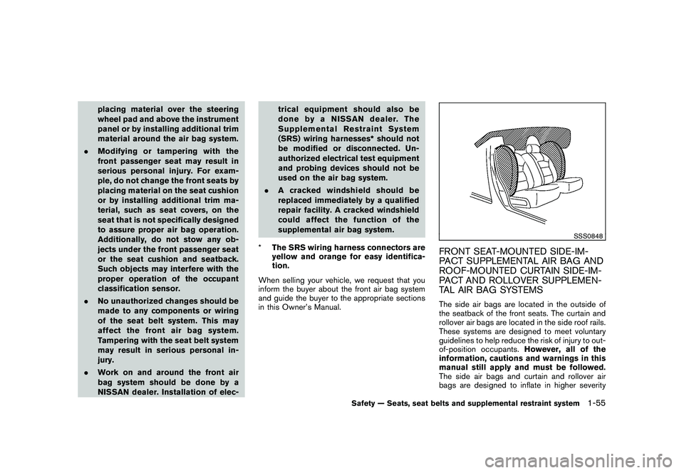
SSS0848
FRONT SEAT-MOUNTED SIDE-IM-
PACT SUPPLEMENTAL AIR BAG AND
ROOF-MOUNTED CURTAIN SIDE-IM-
PACT AND ROLLOVER SUPPLEMEN-
TAL AIR BAG SYSTEMSThe side air bags are located in the outside of
the seatback of the front seats. The curtain and
rollover air bags are located in the side roof rails.
These systems are designed to meet voluntary
guidelines to help reduce the risk of injury to out-
of-position occupants. However, all of the
information, cautions and warnings in this
manual still apply and must be followed.
The side air bags and curtain and rollover air
bags are designed to inflate in higher severity
Safety — Seats, seat belts and supplemental restraint system
1-55
Page 76 of 425
Black plate (72,1)
Model "Z51-D" EDITED: 2009/ 8/ 3
After pretensioner activation, load limiters allow
the seat belt to release webbing (if necessary) to
reduce forces against the chest.
If any abnormality occurs in the pretensioner
system, the supplemental air bag warning light
will not come on, will flash intermittently or
will turn on for 7 seconds and remain on after
the ignition switch has been pushed to the ON
position. In this case, the pretensioner may not
function properly. They must be checked and
repaired. Take your vehicle to the nearest
NISSAN dealer.
When selling your vehicle, we request that you
inform the buyer about the pretensioner system
and guide the buyer to the appropriate sections
in this Owner’s Manual.
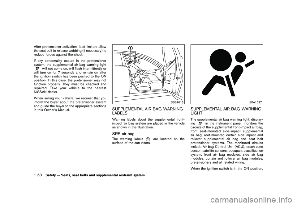
SSS1016
SUPPLEMENTAL AIR BAG WARNING
LABELSWarning labels about the supplemental front-
impact air bag system are placed in the vehicle
as shown in the illustration.SRS air bagThe warning labels
*1
are located on the
surface of the sun visors.
SPA1097
SUPPLEMENTAL AIR BAG WARNING
LIGHTThe supplemental air bag warning light, display-
ing
in the instrument panel, monitors the
circuits of the supplemental front-impact air bag,
front seat-mounted side-impact supplemental
air bag, roof-mounted curtain side-impact and
rollover supplemental air bag and seat belt
pretensioner systems. The monitored circuits
include Air bag Control Unit (ACU) , crash zone
sensor, satellite sensors, occupant classification
system, front air bag modules, side air bag
modules, curtain and rollover air bag modules,
pretensioners and all related wiring.
When the ignition switch is in the ON position,
1-58
Safety — Seats, seat belts and supplemental restraint system
Page 78 of 425
Black plate (7,1)
2 Instruments and controls
Model "Z51-D" EDITED: 2009/ 8/ 3
Instrument panel................................................ 2-2
Meters and gauges ............................................. 2-4
Speedometer and odometer ............................. 2-5
Tachometer ................................................... 2-6
Engine coolant temperature gauge ..................... 2-6
Fuel gauge ................................................... 2-7
Compass (if so equipped) .................................... 2-7
Zone variation change procedure ....................... 2-9
Warning/indicator lights and audible reminders ....... 2-10
Checking bulbs ........................................... 2-10
Warning lights ............................................. 2-10
Indicator lights ............................................. 2-14
Audible reminders ........................................ 2-16
Dot matrix liquid crystal display ............................ 2-17
Indicators for operation .................................. 2-18
Indicators for maintenance .............................. 2-20
Trip computer .............................................. 2-21
Security systems .............................................. 2-25
Vehicle security system (if so equipped) ............ 2-25
NISSAN Vehicle Immobilizer System ................. 2-27
Windshield wiper and washer switch .................... 2-28
Rain-sensing auto wiper system
(if so equipped) ........................................... 2-29
Rear window wiper and washer switch .................. 2-30
Rear window and outside mirror defroster switch ..... 2-31Headlight and turn signal switch
.......................... 2-32
Xenon headlights (if so equipped) .................... 2-32
Headlight switch .......................................... 2-32
Turn signal switch ........................................ 2-35
Fog light switch (if so equipped) ...................... 2-35
Hazard warning flasher switch ............................. 2-36
Horn ............................................................. 2-36
Heated seats (if so equipped) ............................. 2-37
Clock ............................................................ 2-38
Models without color display ........................... 2-38
Models with color display ............................... 2-38
Vehicle Dynamic Control (VDC) OFF switch ........... 2-39
Power outlet ................................................... 2-39
Cigarette lighter and ashtray (if so equipped) .......... 2-40
Storage ......................................................... 2-41
Cup holders ................................................ 2-41
Sunglasses holder ........................................ 2-42
Glove box .................................................. 2-43
Console box ............................................... 2-43
Storage box (if so equipped) .......................... 2-44
Cargo floor box ........................................... 2-45
Luggage side box ......................................... 2-45
Cargo cover (if so equipped) .......................... 2-45
Luggage hooks ............................................ 2-46
Roof rack (if so equipped) .............................. 2-47
Coat hooks ................................................. 2-48
Page 80 of 425
Black plate (76,1)
Model "Z51-D" EDITED: 2009/ 8/ 3
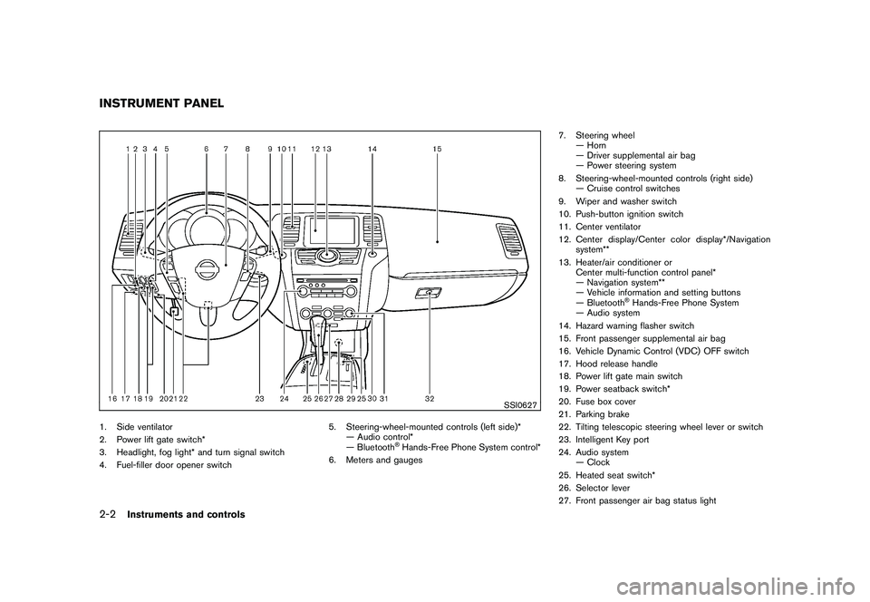
SSI0627
1. Side ventilator
2. Power lift gate switch*
3. Headlight, fog light* and turn signal switch
4. Fuel-filler door opener switch5. Steering-wheel-mounted controls (left side)*
— Audio control*
— Bluetooth
®Hands-Free Phone System control*
6. Meters and gauges 7. Steering wheel
— Horn
— Driver supplemental air bag
— Power steering system
8. Steering-wheel-mounted controls (right side) — Cruise control switches
9. Wiper and washer switch
10. Push-button ignition switch
11. Center ventilator
12. Center display/Center color display*/Navigation system**
13. Heater/air conditioner or Center multi-function control panel*
— Navigation system**
— Vehicle information and setting buttons
— Bluetooth
®Hands-Free Phone System
— Audio system
14. Hazard warning flasher switch
15. Front passenger supplemental air bag
16. Vehicle Dynamic Control (VDC) OFF switch
17. Hood release handle
18. Power lift gate main switch
19. Power seatback switch*
20. Fuse box cover
21. Parking brake
22. Tilting telescopic steering wheel lever or switch
23. Intelligent Key port
24. Audio system — Clock
25. Heated seat switch*
26. Selector lever
27. Front passenger air bag status light
INSTRUMENT PANEL2-2
Instruments and controls
Page 83 of 425
Black plate (79,1)
Model "Z51-D" EDITED: 2009/ 8/ 3
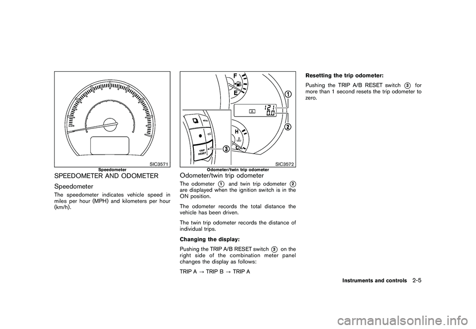
SIC3571
Speedometer
SPEEDOMETER AND ODOMETER
SpeedometerThe speedometer indicates vehicle speed in
miles per hour (MPH) and kilometers per hour
(km/h) .
SIC3572
Odometer/twin trip odometer
Odometer/twin trip odometerThe odometer
*1
and twin trip odometer
*2
are displayed when the ignition switch is in the
ON position.
The odometer records the total distance the
vehicle has been driven.
The twin trip odometer records the distance of
individual trips.
Changing the display:
Pushing the TRIP A/B RESET switch
*3
on the
right side of the combination meter panel
changes the display as follows:
TRIP A ?TRIP B ?TRIP A Resetting the trip odometer:
Pushing the TRIP A/B RESET switch
*3
for
more than 1 second resets the trip odometer to
zero.
Instruments and controls
2-5
Page 99 of 425
Black plate (95,1)
Model "Z51-D" EDITED: 2009/ 8/ 3
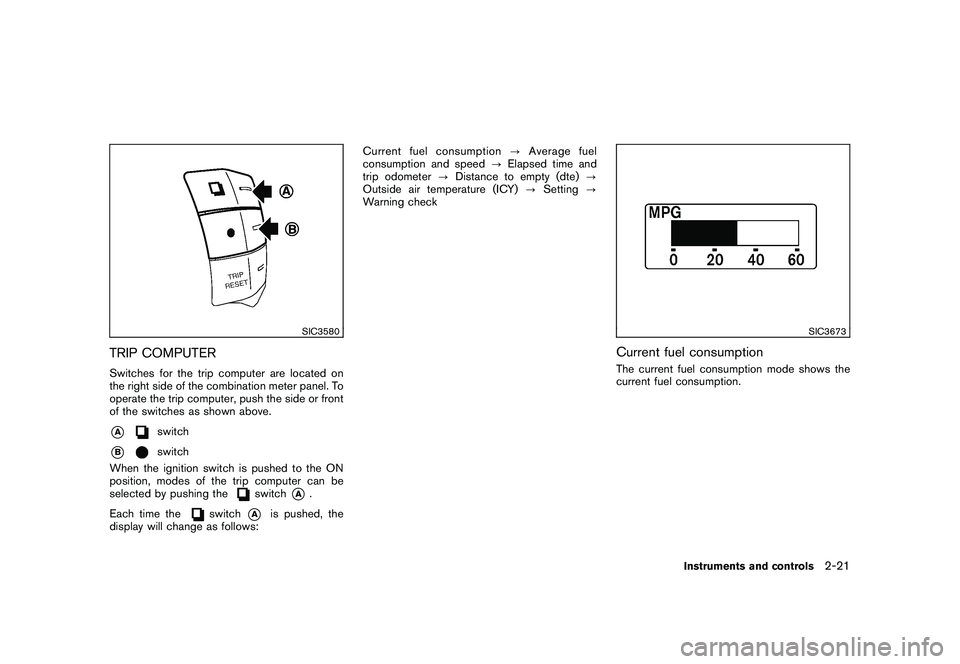
SIC3580
TRIP COMPUTERSwitches for the trip computer are located on
the right side of the combination meter panel. To
operate the trip computer, push the side or front
of the switches as shown above.*A
switch
*B
switch
When the ignition switch is pushed to the ON
position, modes of the trip computer can be
selected by pushing the
switch
*A
.
Each time the
switch
*A
is pushed, the
display will change as follows: Current fuel consumption
?Average fuel
consumption and speed ?Elapsed time and
trip odometer ?Distance to empty (dte) ?
Outside air temperature (ICY) ?Setting ?
Warning check
SIC3673
Current fuel consumptionThe current fuel consumption mode shows the
current fuel consumption.
Instruments and controls
2-21
Page 111 of 425
Black plate (107,1)
Model "Z51-D" EDITED: 2009/ 8/ 3
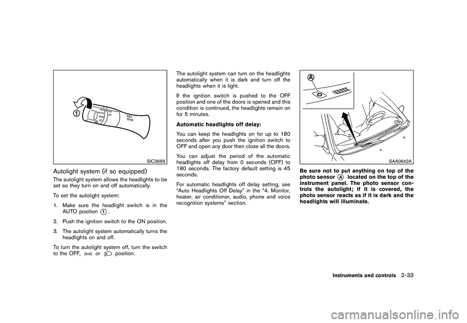
SIC3669
Autolight system (if so equipped)The autolight system allows the headlights to be
set so they turn on and off automatically.
To set the autolight system:
1. Make sure the headlight switch is in theAUTO position
*1.
2. Push the ignition switch to the ON position.
3. The autolight system automatically turns the headlights on and off.
To turn the autolight system off, turn the switch
to the OFF,
or
position. The autolight system can turn on the headlights
automatically when it is dark and turn off the
headlights when it is light.
If the ignition switch is pushed to the OFF
position and one of the doors is opened and this
condition is continued, the headlights remain on
for 5 minutes.
Automatic headlights off delay:
You can keep the headlights on for up to 180
seconds after you push the ignition switch to
OFF and open any door then close all the doors.
You can adjust the period of the automatic
headlights off delay from 0 seconds (OFF) to
180 seconds. The factory default setting is 45
seconds.
For automatic headlights off delay setting, see
“Auto Headlights Off Delay” in the “4. Monitor,
heater, air conditioner, audio, phone and voice
recognition systems” section.
SAA0642A
Be sure not to put anything on top of the
photo sensor
*A
located on the top of the
instrument panel. The photo sensor con-
trols the autolight; if it is covered, the
photo sensor reacts as if it is dark and the
headlights will illuminate.
Instruments and controls
2-33
Page 113 of 425
Black plate (109,1)
Model "Z51-D" EDITED: 2009/ 8/ 3
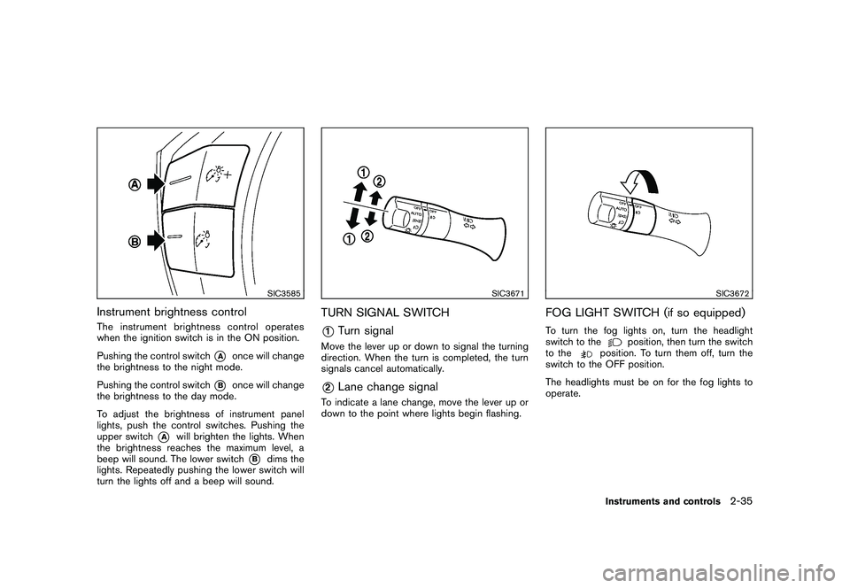
SIC3585
Instrument brightness controlThe instrument brightness control operates
when the ignition switch is in the ON position.
Pushing the control switch
*A
once will change
the brightness to the night mode.
Pushing the control switch
*B
once will change
the brightness to the day mode.
To adjust the brightness of instrument panel
lights, push the control switches. Pushing the
upper switch
*A
will brighten the lights. When
the brightness reaches the maximum level, a
beep will sound. The lower switch
*B
dims the
lights. Repeatedly pushing the lower switch will
turn the lights off and a beep will sound.
SIC3671
TURN SIGNAL SWITCH*1
Turn signal
Move the lever up or down to signal the turning
direction. When the turn is completed, the turn
signals cancel automatically.*2
Lane change signal
To indicate a lane change, move the lever up or
down to the point where lights begin flashing.
SIC3672
FOG LIGHT SWITCH (if so equipped)To turn the fog lights on, turn the headlight
switch to the
position, then turn the switch
to the
position. To turn them off, turn the
switch to the OFF position.
The headlights must be on for the fog lights to
operate.Instruments and controls
2-35
Page 132 of 425
Black plate (128,1)
Model "Z51-D" EDITED: 2009/ 8/ 3
— remain on for about 15 seconds.
. doors are unlocked by pushing the UN-
LOCK button on the Intelligent Key or door
handle request switch with the ignition
switch in the LOCK position
— remain on for about 15 seconds.
. any door is opened and then closed with the
ignition switch in the LOCK position
— remain on for about 15 seconds.
. any door is opened with the ignition switch
in the ACC or ON position
— remain on while the door is opened. When the door is closed, the lights go off.
The lights will also turn off after 30
minutes when the lights remain illumi-
nated after the ignition switch has been
pushed to the OFF or LOCK position to
prevent the battery from becoming dis-
charged.
When the auto interior illumination is set to the
OFF position (see “VEHICLE INFORMATION
AND SETTINGS” in the “4. Monitor, heater, air
conditioner, audio, phone and voice recognition
systems” section) , the lights will illuminate under
the following condition:
. any door is opened with the ignition switch
in any position — remain on while the door is opened.
When the door is closed, the lights go off.
OFF positionWhen the switch is in the OFF position
*3, the
lights will not illuminate, regardless of the
condition.
CAUTION
Do not use for extended periods of time
with the engine stopped. This could
result in a discharged battery.
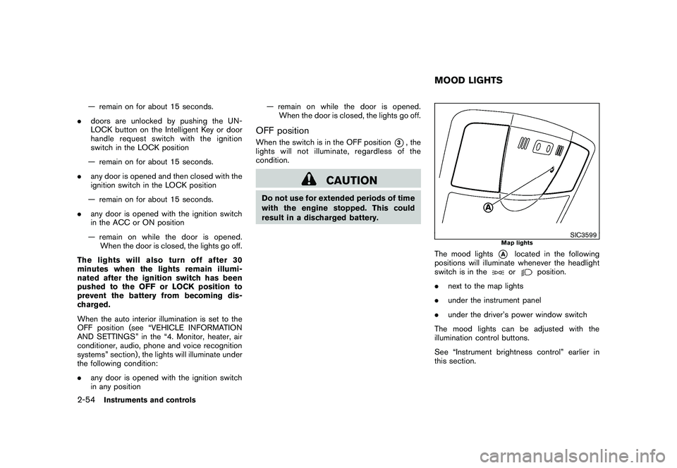
SIC3599
Map lights
The mood lights
*A
located in the following
positions will illuminate whenever the headlight
switch is in theor
position.
. next to the map lights
. under the instrument panel
. under the driver’s power window switch
The mood lights can be adjusted with the
illumination control buttons.
See “Instrument brightness control” earlier in
this section.
MOOD LIGHTS
2-54
Instruments and controls
Page 149 of 425
Black plate (145,1)
Model "Z51-D" EDITED: 2009/ 8/ 3
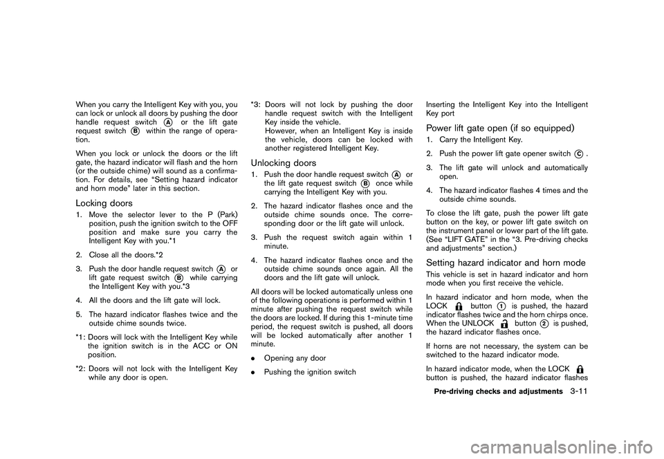
When you carry the Intelligent Key with you, you
can lock or unlock all doors by pushing the door
handle request switch
*A
or the lift gate
request switch
*B
within the range of opera-
tion.
When you lock or unlock the doors or the lift
gate, the hazard indicator will flash and the horn
(or the outside chime) will sound as a confirma-
tion. For details, see “Setting hazard indicator
and horn mode” later in this section.
Locking doors1. Move the selector lever to the P (Park) position, push the ignition switch to the OFF
position and make sure you carry the
Intelligent Key with you.*1
2. Close all the doors.*2
3. Push the door handle request switch
*A
or
lift gate request switch
*B
while carrying
the Intelligent Key with you.*3
4. All the doors and the lift gate will lock.
5. The hazard indicator flashes twice and the outside chime sounds twice.
*1: Doors will lock with the Intelligent Key while the ignition switch is in the ACC or ON
position.
*2: Doors will not lock with the Intelligent Key while any door is open. *3: Doors will not lock by pushing the door
handle request switch with the Intelligent
Key inside the vehicle.
However, when an Intelligent Key is inside
the vehicle, doors can be locked with
another registered Intelligent Key.
Unlocking doors1. Push the door handle request switch
*A
or
the lift gate request switch
*B
once while
carrying the Intelligent Key with you.
2. The hazard indicator flashes once and the outside chime sounds once. The corre-
sponding door or the lift gate will unlock.
3. Push the request switch again within 1 minute.
4. The hazard indicator flashes once and the outside chime sounds once again. All the
doors and the lift gate will unlock.
All doors will be locked automatically unless one
of the following operations is performed within 1
minute after pushing the request switch while
the doors are locked. If during this 1-minute time
period, the request switch is pushed, all doors
will be locked automatically after another 1
minute.
. Opening any door
. Pushing the ignition switch Inserting the Intelligent Key into the Intelligent
Key port
Power lift gate open (if so equipped)1. Carry the Intelligent Key.
2. Push the power lift gate opener switch
*C.
3. The lift gate will unlock and automatically open.
4. The hazard indicator flashes 4 times and the outside chime sounds.
To close the lift gate, push the power lift gate
button on the key, or power lift gate switch on
the instrument panel or lower part of the lift gate.
(See “LIFT GATE” in the “3. Pre-driving checks
and adjustments” section.)
Setting hazard indicator and horn modeThis vehicle is set in hazard indicator and horn
mode when you first receive the vehicle.
In hazard indicator and horn mode, when the
LOCK
button
*1
is pushed, the hazard
indicator flashes twice and the horn chirps once.
When the UNLOCKbutton
*2
is pushed,
the hazard indicator flashes once.
If horns are not necessary, the system can be
switched to the hazard indicator mode.
In hazard indicator mode, when the LOCK
button is pushed, the hazard indicator flashesPre-driving checks and adjustments
3-11