phone NISSAN MURANO 2011 Owner´s Manual
[x] Cancel search | Manufacturer: NISSAN, Model Year: 2011, Model line: MURANO, Model: NISSAN MURANO 2011Pages: 433, PDF Size: 3.7 MB
Page 5 of 433
Black plate (5,1)
Model "Z51-D" EDITED: 2010/ 7/ 23
NISSAN CARES ...
Both NISSAN and your NISSAN dealer are dedicated to serving all your automotive needs. Your satisfaction with your vehicle and your NISSAN dealer are
our primary concerns. Your NISSAN dealer is always available to assist you with all your automobile sales and service needs.We appreciate your interest in NISSAN and thank you for buying a quality NISSAN vehicle.
However, if there is something that your
NISSAN dealer cannot assist you with or you
would like to provide NISSAN directly with
comments or questions, please contact the
NISSAN Consumer Affairs Department using
our toll-free number:
For U.S. customers
1-800-NISSAN-1
(1-800-647-7261)
For Canadian customers 1-800-387-0122
The Consumer Affairs Department will ask for
the following information:
— Your name, address, and telephone number
— Vehicle identification number (attached to the top of the instrument panel on the
driver’s side)
— Date of purchase
— Current odometer reading
— Your NISSAN dealer’s name
— Your comments or questions
OR You can write to NISSAN with the information at:
For U.S. customersNissan North America, Inc.
Consumer Affairs Department
P.O. Box 685003
Franklin, TN 37068-5003
For Canadian customers Nissan Canada Inc.
5290 Orbitor Drive
Mississauga, Ontario L4W 4Z5
NISSAN CUSTOMER CARE
PROGRAM
Page 6 of 433
Black plate (1,1)
Table of
Contents
Model "Z51-D" Edited: 2010/ 7/ 23
Illustrated table of contents
0
Safety — Seats, seat belts and supplemental
restraint system
1
Instruments and controls
2
Pre-driving checks and adjustments
3
Monitor, heater, air conditioner, audio, phone and
voice recognition systems
4
Starting and driving
5
In case of emergency
6
Appearance and care
7
Maintenance and do-it-yourself
8
Technical and consumer information
9
Index
10
Page 12 of 433
Black plate (8,1)
Model "Z51-D" EDITED: 2010/ 7/ 23
SSI0805
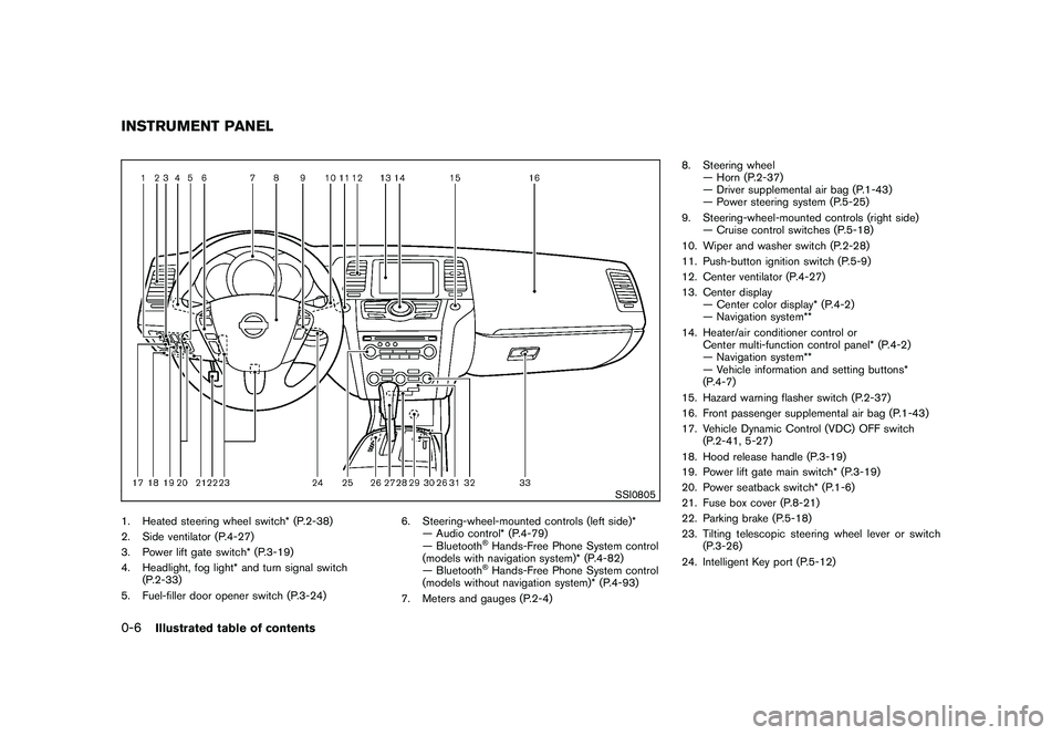
1. Heated steering wheel switch* (P.2-38)
2. Side ventilator (P.4-27)
3. Power lift gate switch* (P.3-19)
4. Headlight, fog light* and turn signal switch(P.2-33)
5. Fuel-filler door opener switch (P.3-24) 6. Steering-wheel-mounted controls (left side)*
— Audio control* (P.4-79)
— Bluetooth
®Hands-Free Phone System control
(models with navigation system)* (P.4-82)
— Bluetooth®Hands-Free Phone System control
(models without navigation system)* (P.4-93)
7. Meters and gauges (P.2-4) 8. Steering wheel
— Horn (P.2-37)
— Driver supplemental air bag (P.1-43)
— Power steering system (P.5-25)
9. Steering-wheel-mounted controls (right side) — Cruise control switches (P.5-18)
10. Wiper and washer switch (P.2-28)
11. Push-button ignition switch (P.5-9)
12. Center ventilator (P.4-27)
13. Center display — Center color display* (P.4-2)
— Navigation system**
14. Heater/air conditioner control or Center multi-function control panel* (P.4-2)
— Navigation system**
— Vehicle information and setting buttons*
(P.4-7)
15. Hazard warning flasher switch (P.2-37)
16. Front passenger supplemental air bag (P.1-43)
17. Vehicle Dynamic Control (VDC) OFF switch (P.2-41, 5-27)
18. Hood release handle (P.3-19)
19. Power lift gate main switch* (P.3-19)
20. Power seatback switch* (P.1-6)
21. Fuse box cover (P.8-21)
22. Parking brake (P.5-18)
23. Tilting telescopic steering wheel lever or switch (P.3-26)
24. Intelligent Key port (P.5-12)
INSTRUMENT PANEL0-6
Illustrated table of contents
Page 76 of 433
Black plate (74,1)
Model "Z51-D" EDITED: 2010/ 7/ 23
SSI0805
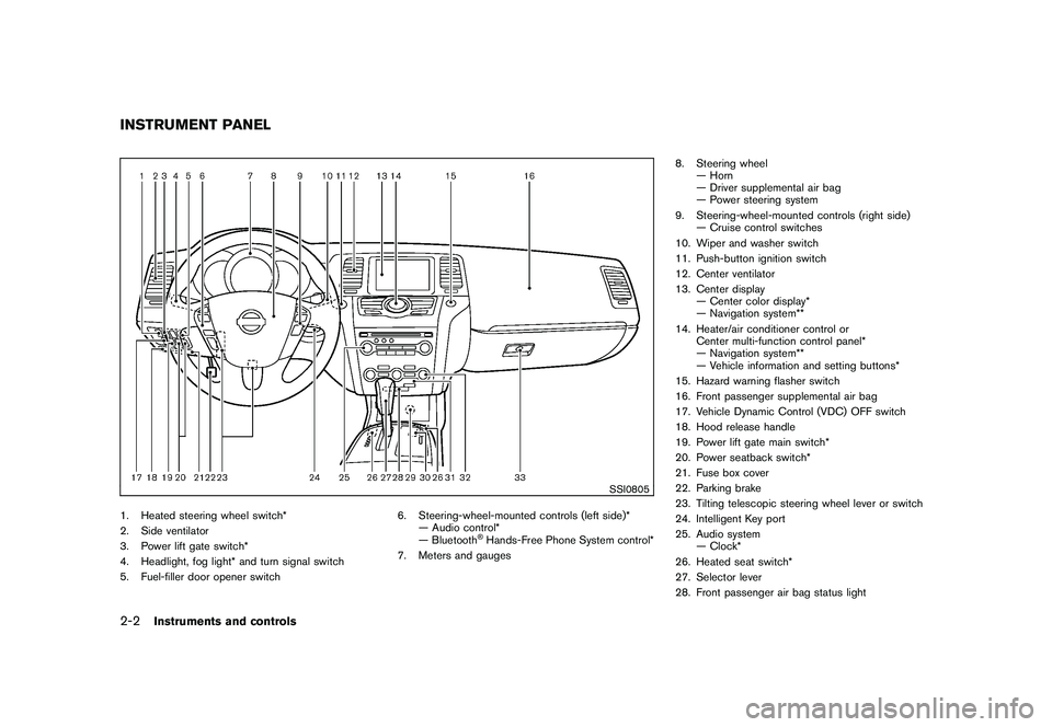
1. Heated steering wheel switch*
2. Side ventilator
3. Power lift gate switch*
4. Headlight, fog light* and turn signal switch
5. Fuel-filler door opener switch6. Steering-wheel-mounted controls (left side)*
— Audio control*
— Bluetooth
®Hands-Free Phone System control*
7. Meters and gauges 8. Steering wheel
— Horn
— Driver supplemental air bag
— Power steering system
9. Steering-wheel-mounted controls (right side) — Cruise control switches
10. Wiper and washer switch
11. Push-button ignition switch
12. Center ventilator
13. Center display — Center color display*
— Navigation system**
14. Heater/air conditioner control or Center multi-function control panel*
— Navigation system**
— Vehicle information and setting buttons*
15. Hazard warning flasher switch
16. Front passenger supplemental air bag
17. Vehicle Dynamic Control (VDC) OFF switch
18. Hood release handle
19. Power lift gate main switch*
20. Power seatback switch*
21. Fuse box cover
22. Parking brake
23. Tilting telescopic steering wheel lever or switch
24. Intelligent Key port
25. Audio system — Clock*
26. Heated seat switch*
27. Selector lever
28. Front passenger air bag status light
INSTRUMENT PANEL2-2
Instruments and controls
Page 95 of 433
Black plate (93,1)
Model "Z51-D" EDITED: 2010/ 7/ 23
INDICATORS FOR MAINTENANCE
1. Engine oil replacement indicatorThis indicator appears when the set time comes
for changing the engine oil. You can set or reset
the distance for changing the engine oil. (See
“TRIP COMPUTER” later in this section.)2. Oil filter replacement indicatorThis indicator appears when the set time comes
for replacing the oil filter. You can set or reset
the distance for replacing the oil filter. (See
“TRIP COMPUTER” later in this section.)3. Tire replacement indicatorThis indicator appears when the set time comes
for replacing tires. You can set or reset the
distance for replacing tires. (See “TRIP COM-
PUTER” later in this section.)4. “OTHER” indicatorThis indicator appears when the set time comes
for replacing items other than the engine oil, oil
filter and tires. You can set or reset the distance
for replacing the items. (See “TRIP COMPU-
TER” later in this section.)
More maintenance reminders are also available
on the center display. (See “HOW TO USE
INFO BUTTON” in the “4. Center display,
heater, air conditioner, audio, phone and voice
recognition systems” section.)
SIC3580
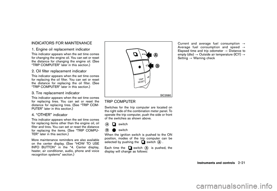
TRIP COMPUTERSwitches for the trip computer are located on
the right side of the combination meter panel. To
operate the trip computer, push the side or front
of the switches as shown above.*A
switch
*B
switch
When the ignition switch is pushed to the ON
position, modes of the trip computer can be
selected by pushing the
switch
*A
.
Each time the
switch
*A
is pushed, the
display will change as follows: Current and average fuel consumption
?
Average fuel consumption and speed ?
Elapsed time and trip odometer ?Distance to
empty (dte) ?Outside air temperature (ICY) ?
Setting ?Warning check
Instruments and controls
2-21
Page 108 of 433
Black plate (106,1)
Model "Z51-D" EDITED: 2010/ 7/ 23
SIC3669
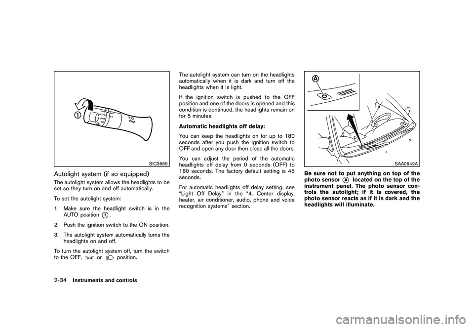
Autolight system (if so equipped)The autolight system allows the headlights to be
set so they turn on and off automatically.
To set the autolight system:
1. Make sure the headlight switch is in theAUTO position
*1.
2. Push the ignition switch to the ON position.
3. The autolight system automatically turns the headlights on and off.
To turn the autolight system off, turn the switch
to the OFF,
or
position. The autolight system can turn on the headlights
automatically when it is dark and turn off the
headlights when it is light.
If the ignition switch is pushed to the OFF
position and one of the doors is opened and this
condition is continued, the headlights remain on
for 5 minutes.
Automatic headlights off delay:
You can keep the headlights on for up to 180
seconds after you push the ignition switch to
OFF and open any door then close all the doors.
You can adjust the period of the automatic
headlights off delay from 0 seconds (OFF) to
180 seconds. The factory default setting is 45
seconds.
For automatic headlights off delay setting, see
“Light Off Delay” in the “4. Center display,
heater, air conditioner, audio, phone and voice
recognition systems” section.
SAA0642A
Be sure not to put anything on top of the
photo sensor
*A
located on the top of the
instrument panel. The photo sensor con-
trols the autolight; if it is covered, the
photo sensor reacts as if it is dark and the
headlights will illuminate.
2-34
Instruments and controls
Page 114 of 433
Black plate (112,1)
Model "Z51-D" EDITED: 2010/ 7/ 23
MODELS WITH COLOR DISPLAYTo adjust the clock on the front color display, use
the SETTING button on the center multi-
function control panel. See “HOW TO USE
SETTING BUTTON” in the “4. Center display,
heater, air conditioner, audio, phone and voice
recognition systems” section.
The clock settings display cannot be operated
while driving. Stop the vehicle in a safe place
and apply the parking brake before setting the
clock.
SIC3802
MODELS WITHOUT COLOR DISPLAYThe digital clock (in the audio unit) displays the
time when the ignition switch is in the ACC or
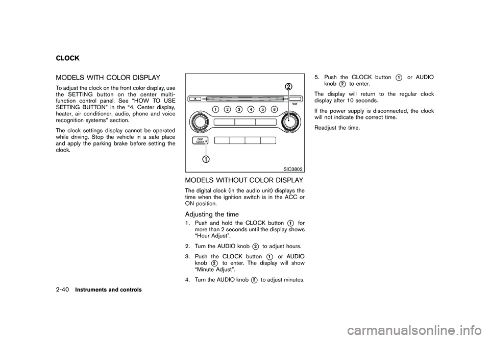
ON position.Adjusting the time1. Push and hold the CLOCK button
*1
for
more than 2 seconds until the display shows
“Hour Adjust”.
2. Turn the AUDIO knob
*2
to adjust hours.
3. Push the CLOCK button*1
or AUDIO
knob
*2
to enter. The display will show
“Minute Adjust”.
4. Turn the AUDIO knob
*2
to adjust minutes. 5. Push the CLOCK button
*1
or AUDIO
knob
*2
to enter.
The display will return to the regular clock
display after 10 seconds.
If the power supply is disconnected, the clock
will not indicate the correct time.
Readjust the time.
CLOCK2-40
Instruments and controls
Page 130 of 433
Black plate (128,1)
Model "Z51-D" EDITED: 2010/ 7/ 23
— remain on for about 15 seconds.
. doors are unlocked by pushing the UN-
LOCK button on the Intelligent Key or door
handle request switch with the ignition
switch in the LOCK position
— remain on for about 15 seconds.
. any door is opened and then closed with the
ignition switch in the LOCK position
— remain on for about 15 seconds.
. any door is opened with the ignition switch
in the ACC or ON position
— remain on while the door is opened. When the door is closed, the lights go off.
The lights will also turn off after 15
minutes when the lights remain illumi-
nated after the ignition switch has been
pushed to the OFF or LOCK position to
prevent the battery from becoming dis-
charged.
When the auto interior illumination is set to the
OFF position (see “VEHICLE INFORMATION
AND SETTINGS” in the “4. Center display,
heater, air conditioner, audio, phone and voice
recognition systems” section) , the lights will
illuminate under the following condition:
. any door is opened with the ignition switch
in any position — remain on while the door is opened.
When the door is closed, the lights go off.
OFF positionWhen the switch is in the OFF position
*3, the
lights will not illuminate, regardless of the
condition.
CAUTION
Do not use for extended periods of time
with the engine stopped. This could
result in a discharged battery.
SIC3599
Map lights
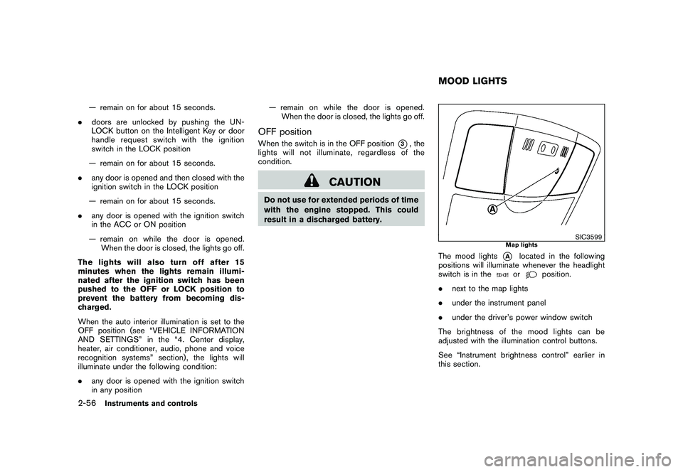
The mood lights
*A
located in the following
positions will illuminate whenever the headlight
switch is in theor
position.
. next to the map lights
. under the instrument panel
. under the driver’s power window switch
The brightness of the mood lights can be
adjusted with the illumination control buttons.
See “Instrument brightness control” earlier in
this section.
MOOD LIGHTS
2-56
Instruments and controls
Page 134 of 433
Black plate (132,1)
Model "Z51-D" EDITED: 2010/ 7/ 23
NOTE:
If programming a garage door opener, etc.,
it is advised to unplug the device during
the “cycling” process to prevent possible
damage to the garage door opener com-
ponents.OPERATING THE HomeLink
®UNIVER-
SAL TRANSCEIVER
HomeLink
®Universal Transceiver (once pro-
grammed) may now be used to activate the
garage door, etc. To operate, simply push the
appropriate programmed HomeLink
®Universal
Transceiver button. The red indicator light will
illuminate while the signal is being transmitted.
PROGRAMMING TROUBLE-DIAGNO-
SISIf HomeLink
®does not quickly learn the hand-
held transmitter information:
. replace the hand-held transmitter batteries
with new batteries.
. position the hand-held transmitter with its
battery area facing away from the Home-
Link
®surface.
. push and hold both the HomeLink
®and
hand-held transmitter buttons without inter-
ruption.
. position the hand-held transmitter 2 to 5 in (50 to 127 mm) away from the HomeLink
®
surface. Hold the transmitter in that position
for up to 15 seconds. If HomeLink
®is not
programmed within that time, try holding the
transmitter in another position - keeping the
indicator light in view at all times.
If you continue to have programming difficulties,
please contact the NISSAN Consumer Affairs
Department. The phone numbers are located in
the Foreword of this Owner’s Manual.
CLEARING THE PROGRAMMED IN-
FORMATIONIndividual buttons cannot be cleared, however to
clear all programming, push and hold the two
outside buttons and release when the indicator
light begins to flash (in approximately 20
seconds) .REPROGRAMMING A SINGLE Home-
Link
®BUTTON
To reprogram a HomeLink
®Universal Transcei-
ver button, complete the following.
1. PushandholdthedesiredHomeLink
®
button. Do not release the button until step
4 has been completed.
2. When the indicator light begins to flash slowly (after 20 seconds), position the
hand-held transmitter 2 to 5 in (50 to 127
mm) away from the HomeLink
®surface. 3. Push and hold the hand-held transmitter
button.
4. The HomeLink
®indicator light will flash, first
slowly and then rapidly. When the indicator
light begins to flash rapidly, release both
buttons.
The HomeLink
®Universal Transceiver button has
now been reprogrammed. The new device can
be activated by pushing the HomeLink
®button
that was just programmed. This procedure will
not affect any other programmed HomeLink
®
buttons.IF YOUR VEHICLE IS STOLENIf your vehicle is stolen, you should change the
codes of any non-rolling code device that has
been programmed into HomeLink
®. Consult the
Owner’s Manual of each device or call the
manufacturer or dealer of those devices for
additional information.
When your vehicle is recovered, you will
need to reprogram the HomeLink
®Univer-
sal Transceiver with your new transmitter
information.
FCC Notice:
This device complies with FCC rules part
15. Operation is subject to the following
two conditions: (1) This device may not
cause harmful interference and (2) This
2-60
Instruments and controls
Page 139 of 433
Black plate (137,1)
Model "Z51-D" EDITED: 2010/ 7/ 23
CAUTION
Do not allow the NISSAN Vehicle Im-
mobilizer System key, which contains
an electrical transponder, to come in
contactwithsaltwater.Thiscould
cause the system to malfunction.INTELLIGENT KEY SYSTEMYour vehicle can only be driven with the
Intelligent Keys which are registered to your
vehicle’s Intelligent Key system components and
NISSAN Vehicle Immobilizer System compo-
nents. As many as 4 Intelligent Keys can be
registered and used with one vehicle. The new
keys must be registered by a NISSAN dealer
prior to use with the Intelligent Key system and
NISSAN Vehicle Immobilizer System of your
vehicle. Since the registration process requires
erasing all memory in the Intelligent Key compo-
nents when registering new keys, be sure to take
all Intelligent Keys that you have to the NISSAN
dealer.
CAUTION
.Be sure to carry the Intelligent Key
with you when driving. The Intelli-
gent Key is a precision device with a
built-in transmitter. To avoid dama- ging it, please note the following.
— The Intelligent Key is water
resistant; however, wetting may
damage the Intelligent Key. If
the Intelligent Key gets wet,
immediately wipe until it is com-
pletely dry.
— Do not bend, drop or strike it against another object.
— Do not place the Intelligent Key foranextendedperiodina
place where temperatures ex-
ceed 140 8F (60 8C) .
— Do not change or modify the Intelligent Key.
— Do not use a magnet key holder.
— Do not place the Intelligent Key near an electric appliance such
as a television set, personal
computer or cellular phone.
— Do not allow the Intelligent Key to come into contact with water
or salt water, and do not wash it
in a washing machine. This
could affect the system function.
. If an Intelligent Key is lost or stolen,
NISSAN recommends erasing the ID
code of that Intelligent Key. This will prevent the Intelligent Key from
unauthorized use to unlock the
vehicle. For information regarding
the erasing procedure, please con-
tact a NISSAN dealer.
Pre-driving checks and adjustments
3-3