seat memory NISSAN MURANO 2021 Owner´s Manual
[x] Cancel search | Manufacturer: NISSAN, Model Year: 2021, Model line: MURANO, Model: NISSAN MURANO 2021Pages: 508, PDF Size: 3.5 MB
Page 22 of 508

Seat lif ter (driver's seat)
Pull up or push down the adjusting lever to
adjust the seat height until the desired po-
sition is achieved.
FRONT POWER SEAT ADJUSTMENT
(if so equipped)
Operating tips
• The power seat motor has an auto-resetoverload protection circuit. If the motor
stops during operation, wait 30 seconds
then reactivate the switch.
• Do not operate the power seat switch for a long period of time when the engine is
off. This will discharge the battery.
For additional information, see “Memory
seat” (P. 3-37).
Forward and backward
Moving the switch as shown will slide the
seat forward or backward to the desired
position.
Reclining
Move the recline switch as shown until the
desired angle is obtained.
The reclining feature allows adjustment of
the seatback for occupants of different
sizes for added comfort and to help obtain
proper seat belt fit. For additional informa-
tion, see “Precautions on seat belt usage”
(P. 1-13). Also, the seatback can be reclined
LRS2202LRS2662
1-4Safety-Seats, seat belts and supplemental restraint system
Page 114 of 508
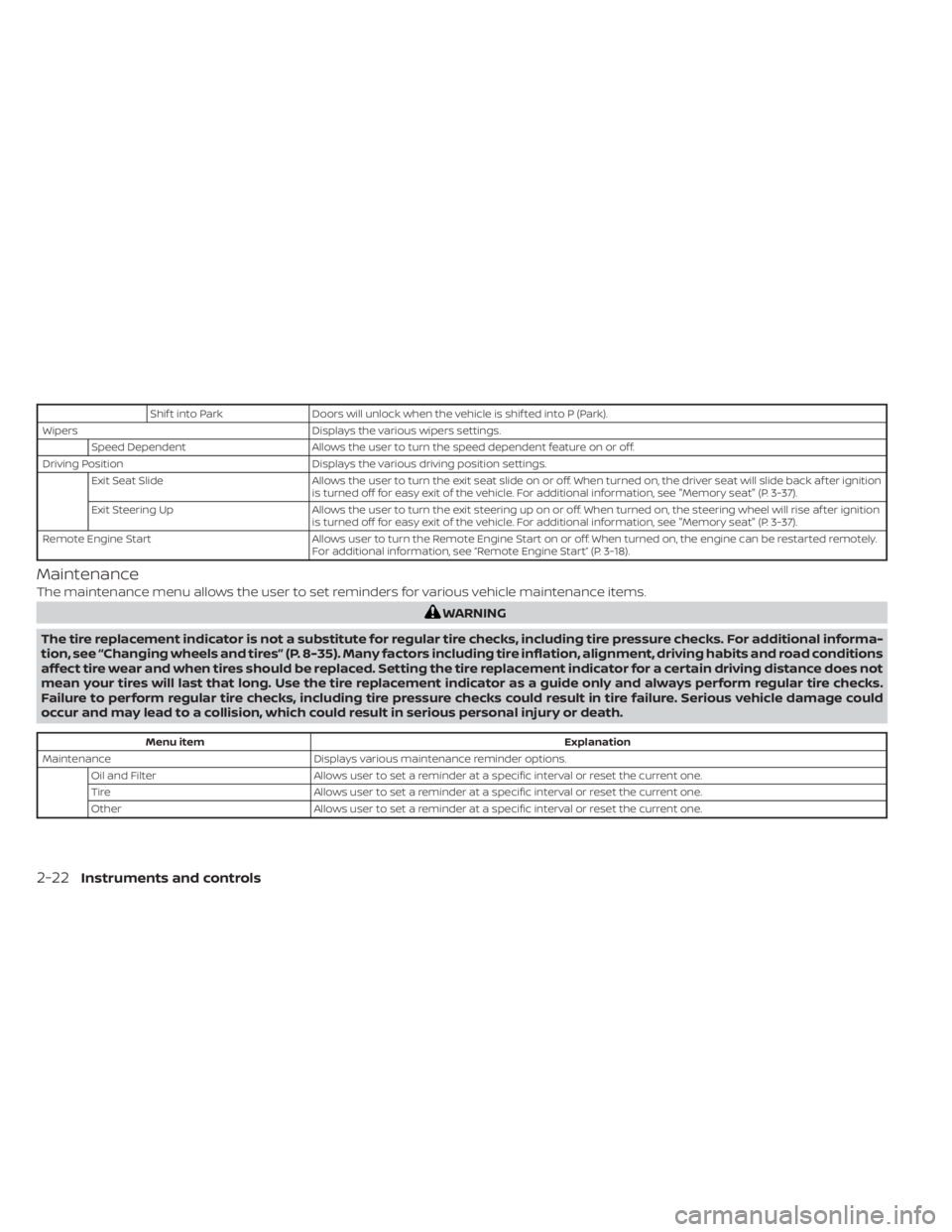
Shif t into ParkDoors will unlock when the vehicle is shif ted into P (Park).
Wipers Displays the various wipers settings.
Speed Dependent Allows the user to turn the speed dependent feature on or off.
Driving Position Displays the various driving position settings.
Exit Seat Slide Allows the user to turn the exit seat slide on or off. When turned on, the driver seat will slide back af ter ignition
is turned off for easy exit of the vehicle. For additional information, see "Memory seat" (P. 3-37).
Exit Steering Up Allows the user to turn the exit steering up on or off. When turned on, the steering wheel will rise af ter ignition
is turned off for easy exit of the vehicle. For additional information, see "Memory seat" (P. 3-37).
Remote Engine Start Allows user to turn the Remote Engine Start on or off. When turned on, the engine can be restarted remotely.
For additional information, see “Remote Engine Start” (P. 3-18).
Maintenance
The maintenance menu allows the user to set reminders for various vehicle maintenance items.
WARNING
The tire replacement indicator is not a substitute for regular tire checks, including tire pressure checks. For additional informa-
tion, see “Changing wheels and tires” (P. 8-35). Many factors including tire inflation, alignment, driving habits and road conditions
affect tire wear and when tires should be replaced. Setting the tire replacement indicator for a certain driving distance does not
mean your tires will last that long. Use the tire replacement indicator as a guide only and always perform regular tire checks.
Failure to perform regular tire checks, including tire pressure checks could result in tire failure. Serious vehicle damage could
occur and may lead to a collision, which could result in serious personal injury or death.
Menu item Explanation
Maintenance Displays various maintenance reminder options.
Oil and Filter Allows user to set a reminder at a specific interval or reset the current one.
Tire Allows user to set a reminder at a specific interval or reset the current one.
Other Allows user to set a reminder at a specific interval or reset the current one.
2-22Instruments and controls
Page 115 of 508
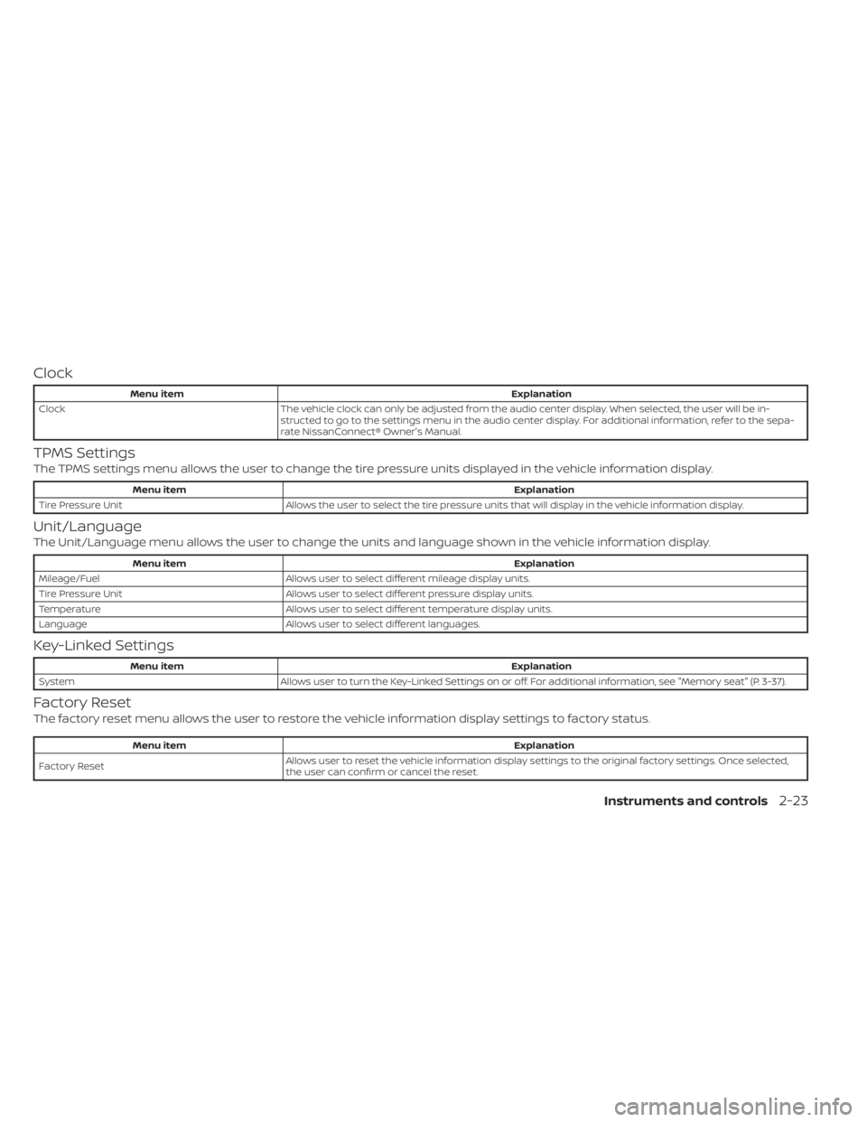
Clock
Menu itemExplanation
Clock The vehicle clock can only be adjusted from the audio center display. When selected, the user will be in-
structed to go to the settings menu in the audio center display. For additional information, refer to the sepa-
rate NissanConnect® Owner's Manual.
TPMS Settings
The TPMS settings menu allows the user to change the tire pressure units displayed in the vehicle information display.
Menu item Explanation
Tire Pressure Unit Allows the user to select the tire pressure units that will display in the vehicle information display.
Unit/Language
The Unit/Language menu allows the user to change the units and language shown in the vehicle information display.
Menu item Explanation
Mileage/Fuel Allows user to select different mileage display units.
Tire Pressure Unit Allows user to select different pressure display units.
Temperature Allows user to select different temperature display units.
Language Allows user to select different languages.
Key-Linked Settings
Menu item Explanation
System Allows user to turn the Key-Linked Settings on or off. For additional information, see "Memory seat" (P. 3-37).
Factory Reset
The factory reset menu allows the user to restore the vehicle information display settings to factory status.
Menu item Explanation
Factory Reset Allows user to reset the vehicle information display setti
ngs to the original factory settings. Once selected,
the user can confirm or cancel the reset.
Instruments and controls2-23
Page 165 of 508
Memory seat (if so equipped)...................3-37
Memory storage function (key-link) ..........3-37
Memory storage function (switch) ...........3-38 Entry/exit function (if so equipped)
..........3-38
System operation ........................... 3-39
Page 196 of 508
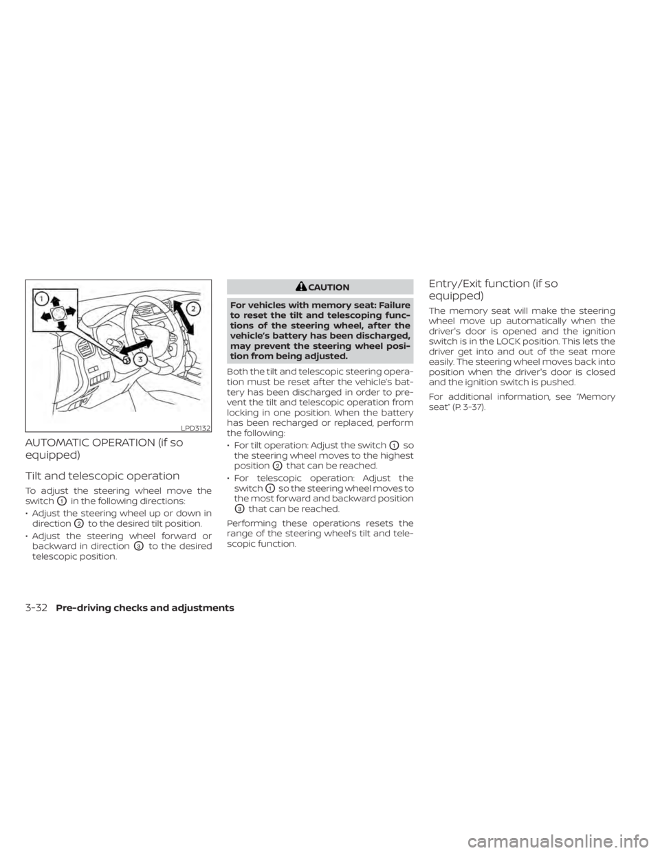
AUTOMATIC OPERATION (if so
equipped)
Tilt and telescopic operation
To adjust the steering wheel move the
switch
O1in the following directions:
• Adjust the steering wheel up or down in direction
O2to the desired tilt position.
• Adjust the steering wheel forward or backward in direction
O3to the desired
telescopic position.
CAUTION
For vehicles with memory seat: Failure
to reset the tilt and telescoping func-
tions of the steering wheel, af ter the
vehicle’s battery has been discharged,
may prevent the steering wheel posi-
tion from being adjusted.
Both the tilt and telescopic steering opera-
tion must be reset af ter the vehicle’s bat-
tery has been discharged in order to pre-
vent the tilt and telescopic operation from
locking in one position. When the battery
has been recharged or replaced, perform
the following:
• For tilt operation: Adjust the switch
O1so
the steering wheel moves to the highest
position
O2that can be reached.
• For telescopic operation: Adjust the switch
O1so the steering wheel moves to
the most forward and backward position
O3that can be reached.
Performing these operations resets the
range of the steering wheel’s tilt and tele-
scopic function.
Entry/Exit function (if so
equipped)
The memory seat will make the steering
wheel move up automatically when the
driver's door is opened and the ignition
switch is in the LOCK position. This lets the
driver get into and out of the seat more
easily. The steering wheel moves back into
position when the driver's door is closed
and the ignition switch is pushed.
For additional information, see “Memory
seat” (P. 3-37).
LPD3132
3-32Pre-driving checks and adjustments
Page 200 of 508
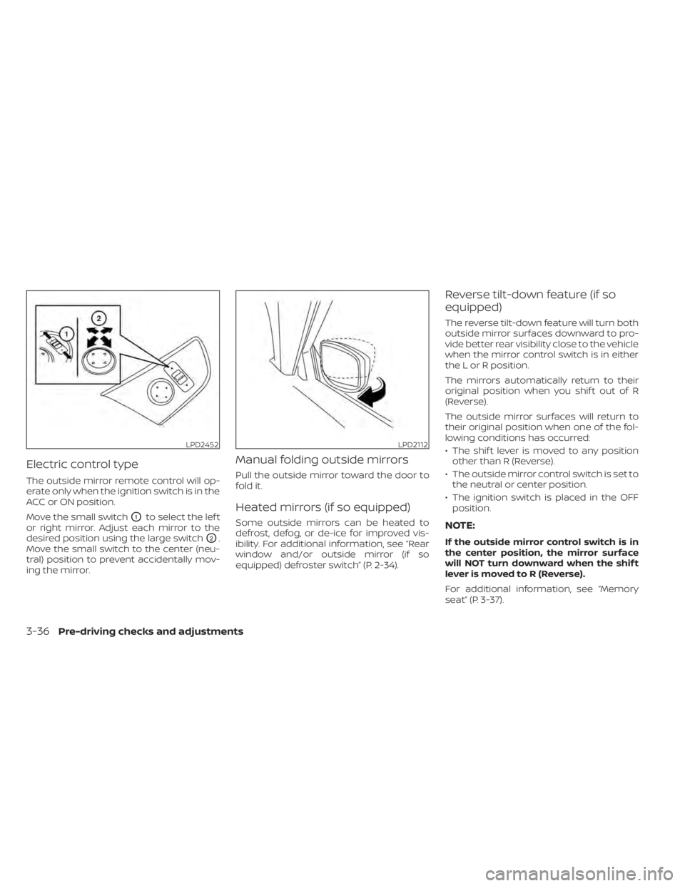
Electric control type
The outside mirror remote control will op-
erate only when the ignition switch is in the
ACC or ON position.
Move the small switch
O1to select the lef t
or right mirror. Adjust each mirror to the
desired position using the large switch
O2.
Move the small switch to the center (neu-
tral) position to prevent accidentally mov-
ing the mirror.
Manual folding outside mirrors
Pull the outside mirror toward the door to
fold it.
Heated mirrors (if so equipped)
Some outside mirrors can be heated to
defrost, defog, or de-ice for improved vis-
ibility. For additional information, see “Rear
window and/or outside mirror (if so
equipped) defroster switch” (P. 2-34).
Reverse tilt-down feature (if so
equipped)
The reverse tilt-down feature will turn both
outside mirror surfaces downward to pro-
vide better rear visibility close to the vehicle
when the mirror control switch is in either
the L or R position.
The mirrors automatically return to their
original position when you shif t out of R
(Reverse).
The outside mirror surfaces will return to
their original position when one of the fol-
lowing conditions has occurred:
• The shif t lever is moved to any position other than R (Reverse).
• The outside mirror control switch is set to the neutral or center position.
• The ignition switch is placed in the OFF position.
NOTE:
If the outside mirror control switch is in
the center position, the mirror surface
will NOT turn downward when the shif t
lever is moved to R (Reverse).
For additional information, see “Memory
seat” (P. 3-37).
LPD2452LPD2112
3-36Pre-driving checks and adjustments
Page 201 of 508
The memory seat system has three
features:
• Memory storage function (Key-link)
• Memory storage function (Switch)
• Entry/exit function
Key-link, when enabled, automatically re-
tains the driver’s last seat, outside mirrors
and steering wheel (if so equipped) posi-
tions for that specific key when the ignition
is turned from ON to OFF.
Each memory switch button (1 or 2) on the
driver’s door can also store one additional
position which is independent of the key-
linked position.
MEMORY STORAGE FUNCTION
(key-link)
Use the following process to setup key-link:
1. Unlock the vehicle with the desired Intel-ligent Key while the ignition is OFF.
2. Place the ignition in the ON position.
3. Within the “Settings” menu of the vehicle information display, select “Key-Linked
Settings” and press the OK button on the
steering switch. 4. While in the menu, press the OK button
on the steering switch to turn the sys-
tem ON/OFF.
Once step 4 is completed, every time the
ignition is switched from ON to OFF, the
memory positions of the driver’s seat, out-
side mirrors and automatic steering wheel
(if so equipped) are linked to the Intelligent
Key.
Follow the same procedure if you want
to link the 2nd, 3rd or 4th Intelligent Key.
NOTE:
If new memory positions are set prior to
turning the ignition from ON to OFF, the
previously linked memory positions for
the respective key will be overwritten by
new positions.
Recalling Intelligent Key memory
positions
If the “Key-Linked Settings” are enabled in
the vehicle information display for that par-
ticular key, every time you enter the vehicle
the driver’s seat, mirrors and automatic
steering wheel (if so equipped) will auto-
matically move to the driver’s last position
of the respective Intelligent Key.
NOTE:
The key-linked memory positions can be
different from the positions stored in the
memory switch (1 or 2).
MEMORY SEAT (if so equipped)
Pre-driving checks and adjustments3-37
Page 202 of 508
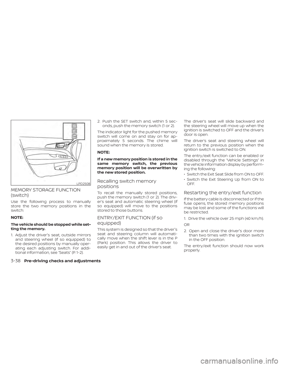
MEMORY STORAGE FUNCTION
(switch)
Use the following process to manually
store the two memory positions in the
switch:
NOTE:
The vehicle should be stopped while set-
ting the memory.
1. Adjust the driver's seat, outside mirrorsand steering wheel (if so equipped) to
the desired positions by manually oper-
ating each adjusting switch. For addi-
tional information, see “Seats” (P. 1-2). 2. Push the SET switch and, within 5 sec-
onds, push the memory switch (1 or 2).
The indicator light for the pushed memory
switch will come on and stay on for ap-
proximately 5 seconds. The chime will
sound when the memory is stored.
NOTE:
If a new memory position is stored in the
same memory switch, the previous
memory position will be overwritten by
the new stored position.
Recalling switch memory
positions
To recall the manually stored positions,
push the memory switch (1 or 2). The driv-
er’s seat and automatic steering wheel (if
so equipped) will move to the positions
stored to those buttons.
ENTRY/EXIT FUNCTION (if so
equipped)
This system is designed so that the driver's
seat and steering column will automati-
cally move when the shif t lever is in the P
(Park) position. This allows the driver to
easily get in and out of the driver’s seat. The driver’s seat will slide backward and
the steering wheel will move up when the
ignition is switched to OFF and the driver’s
door is open.
The driver’s seat and steering wheel will
return to the previous position when the
ignition switch is switched to ON.
The entry/exit function can be enabled or
disabled through the “Vehicle Settings” in
the vehicle information display by perform-
ing the following:
• Switch the Exit Seat Slide from ON to OFF.
• Switch the Exit Steering Up from ON to
OFF.
Restarting the entry/exit function
If the battery cable is disconnected or if the
fuse opens, the stored memory positions
may be lost and some of the functions will
be restricted.
1. Drive the vehicle over 25 mph (40 km/h).
OR
2. Open and close the driver's door more than two times with the ignition switch
in the OFF position.
The entry/exit function should now work
properly.
LPD2508
3-38Pre-driving checks and adjustments
Page 203 of 508
SYSTEM OPERATION
The memory seat system will not work or
will stop operating under the following
conditions:
• When the vehicle speed is above 4 mph (7km/h).
• When any of the memory switches are pushed while the memory seat is
operating.
• When the switch for the driver’s seat and steering column is pushed while the
memory seat is operating.
• When the seat has already been moved to the memorized position.
• When no seat position is stored in the memory switch.
• When the shif t lever is moved from P (Park) to any other position.
Pre-driving checks and adjustments3-39
Page 498 of 508

J
Jump starting..............6-10,8-14
K
Key.........................3-2Key fob battery replacement........8-23Keyless entryWith Intelligent Key system
(See Intelligent Key system)
.......3-12KeysNISSAN Intelligent Key®........3-2,3-7NISSAN Vehicle Immobilizer System
keys..................... .3-4
L
Label
Tire and Loading Information label. .10-13LabelsAir conditioner specification label. . .10-13C.M.V.S.S. certification label.......10-12Emission control information label. .10-12Engine serial number..........10-12F.M.V.S.S. certification label........10-12Tire and Loading Information label. .10-13Vehicle identification number (VIN)
plate.................... .10-11Warning labels (for SRS)..........1-70Lane Departure Warning (LDW).......5-27
LATCH (Lower Anchors and Tethers for
CHildren) System...............1-29License plate
Installing the license plate........10-14Lif tgate......................3-21Lif tgate release................3-27LightAir bag warning light.........1-70,2-11Brake light (See stop light)........8-25Bulb check/instrument panel......2-9Bulb replacement.............8-25Charge warning light...........2-10Console light................2-65Exterior and Interior lights........8-25Fog light switch...............2-41Fog lights..................8-25Headlight and turn signal switch. . . .2-35Headlight control switch.........2-35Headlights..................8-25Interior light................ .2-64Light bulbs.................8-25Low tire pressure warning light.....2-12Low windshield-washer fluid warning
light......................2-25Personal lights...............2-66Security indicator light..........2-10Spotlights (See map light)........2-65Warning/indicator lights and audible
reminders................2-9, 2-11Lights......................8-25Map lights................. .2-65Lock
Child safety rear door lock.........3-7
Door locks................. .3-5Fuel-filler door lock opener lever. . . .3-29Lif tgate release...............3-27Power door locks..............3-6Loose fuel cap warning...........2-25Low fuel warning light.....2-10,2-14,2-25Low tire pressure warning light.......2-12Low windshield-washer fluid warning
light.......................2-25Luggage (See vehicle loading
information)..................10-15Luggage hook.................2-57Luggage rack (see roof rack)........2-58
M
Maintenance
General maintenance...........9-2Inside the vehicle..............9-3Maintenance precautions.........8-2Outside the vehicle.............9-3Seat belt maintenance..........1-24Under the hood and vehicle.......9-4Maintenance requirements..........9-2Maintenance schedules............9-7Malfunction indicator light..........2-13Manual front seat adjustment........1-3Map lights.................. .2-65Map pocket...................2-52Memory seat..................3-37Meters and gauges..............2-4Instrument brightness control.....2-40
11-4