NISSAN MURANO 2023 Owners Manual
Manufacturer: NISSAN, Model Year: 2023, Model line: MURANO, Model: NISSAN MURANO 2023Pages: 518, PDF Size: 5.46 MB
Page 141 of 518
3. When the seat is warmed or before youleave the vehicle, be sure to turn the
switch off.
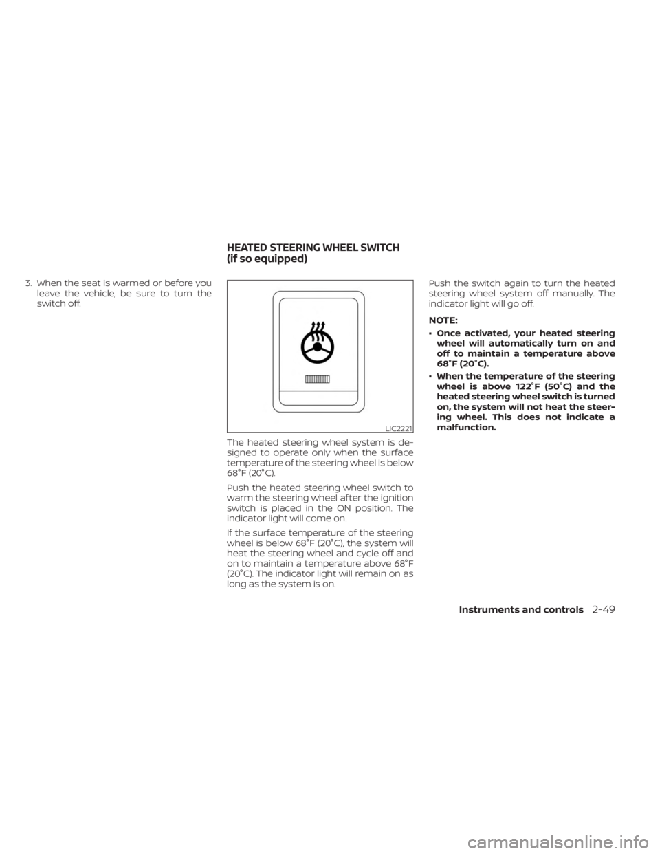
The heated steering wheel system is de-
signed to operate only when the surface
temperature of the steering wheel is below
68°F (20°C).
Push the heated steering wheel switch to
warm the steering wheel af ter the ignition
switch is placed in the ON position. The
indicator light will come on.
If the surface temperature of the steering
wheel is below 68°F (20°C), the system will
heat the steering wheel and cycle off and
on to maintain a temperature above 68°F
(20°C). The indicator light will remain on as
long as the system is on. Push the switch again to turn the heated
steering wheel system off manually. The
indicator light will go off.
NOTE:
• Once activated, your heated steering
wheel will automatically turn on and
off to maintain a temperature above
68°F (20°C).
• When the temperature of the steering wheel is above 122°F (50°C) and the
heated steering wheel switch is turned
on, the system will not heat the steer-
ing wheel. This does not indicate a
malfunction.
LIC2221
HEATED STEERING WHEEL SWITCH
(if so equipped)
Instruments and controls2-49
Page 142 of 518
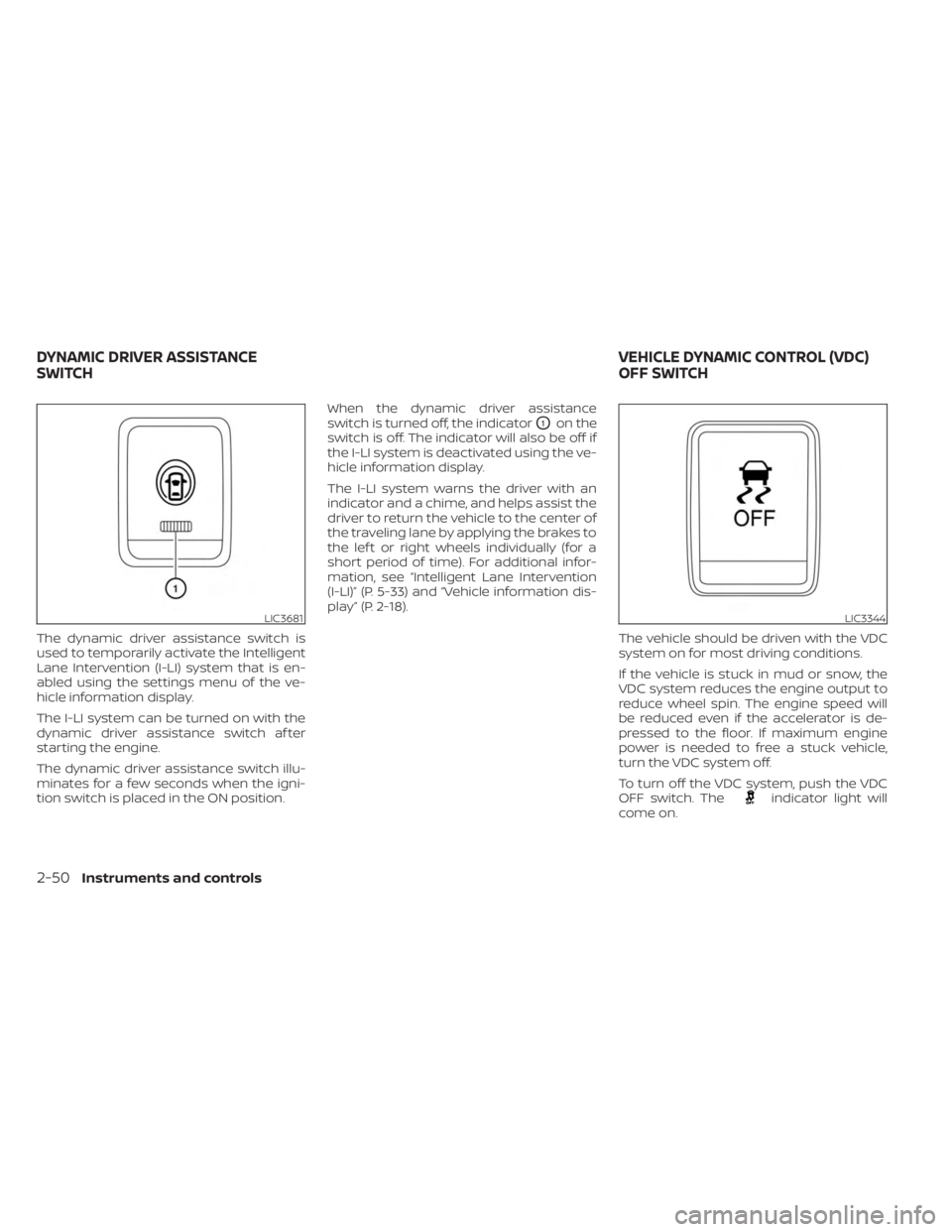
The dynamic driver assistance switch is
used to temporarily activate the Intelligent
Lane Intervention (I-LI) system that is en-
abled using the settings menu of the ve-
hicle information display.
The I-LI system can be turned on with the
dynamic driver assistance switch af ter
starting the engine.
The dynamic driver assistance switch illu-
minates for a few seconds when the igni-
tion switch is placed in the ON position.When the dynamic driver assistance
switch is turned off, the indicator
O1on the
switch is off. The indicator will also be off if
the I-LI system is deactivated using the ve-
hicle information display.
The I-LI system warns the driver with an
indicator and a chime, and helps assist the
driver to return the vehicle to the center of
the traveling lane by applying the brakes to
the lef t or right wheels individually (for a
short period of time). For additional infor-
mation, see “Intelligent Lane Intervention
(I-LI)” (P. 5-33) and “Vehicle information dis-
play” (P. 2-18).
The vehicle should be driven with the VDC
system on for most driving conditions.
If the vehicle is stuck in mud or snow, the
VDC system reduces the engine output to
reduce wheel spin. The engine speed will
be reduced even if the accelerator is de-
pressed to the floor. If maximum engine
power is needed to free a stuck vehicle,
turn the VDC system off.
To turn off the VDC system, push the VDC
OFF switch. The
indicator light will
come on.
LIC3681LIC3344
DYNAMIC DRIVER ASSISTANCE
SWITCH VEHICLE DYNAMIC CONTROL (VDC)
OFF SWITCH
2-50Instruments and controls
Page 143 of 518
Push the VDC OFF switch again or restart
the engine to turn on the system. For addi-
tional information, see “Vehicle Dynamic
Control (VDC) system” (P. 5-123).
When the VDC OFF switch is used to turn off
the VDC system, the Automatic Emergency
Braking (AEB) with Pedestrian Detection
and Rear Automatic Braking (RAB) systems
are also turned off. For additional informa-
tion, see “Automatic Emergency Braking
(AEB) with Pedestrian Detection”(P. 5-88)
and “Rear Automatic Braking (RAB)” (P. 5-83).EMERGENCY SUPPORT
NissanConnect® Services provide various
services to support dealing with emergen-
cies of the subscribed vehicle and the
driver.
For example, in case of an illness or serious
injury, you can seek support by pressing
the in-vehicle Emergency Call (SOS) button
and connecting to the NissanConnect®
Services Response Center. The
NissanConnect® Services Response Cen-
ter can specif y the location of the vehicle
via GPS, and the information will be sent to
the police or other agencies as needed.
For information about other
NissanConnect® Services emergency sup-
port related services, contact the
NissanConnect® Customer Support line at
1–855–426–6628 or refer to the
NissanConnect® Services website
www.nissanusa.com/connect (for U.S.) or
www.nissan.ca/nissanconnect (English) /
www.nissan.ca/nissanconnect/fr (French)
(for Canada).
WARNING
• Please note that the Automatic Colli-
sion Notification service and Emer-
gency Call function cannot be used in
the following conditions:
–
Emergency functions and services
will not be available without a paid
subscription to NissanConnect®
Services.
– The NissanConnect® Services net- work system is disabled.
– The vehicle moves outside the service area where the TCU
(Telematics Control Unit) is con-
nected to the system.
– The vehicle is outside the area where the cellular network service
is receivable.
–
The vehicle is in a location with poor
signal reception such as tunnels,
underground parking garages, be-
hind buildings or in mountainous
areas.
– The line is busy.
– The TCU (Telematics Control Unit) or other systems of your vehicle
are not working properly.
EMERGENCY CALL (SOS) BUTTON (if
so equipped)
Instruments and controls2-51
Page 144 of 518
– It may not be possible to make anemergency call depending on the
severity of a collision and/or
emergency.
• Park the vehicle in a safe location and
set the parking brake before operat-
ing the Emergency Call (SOS) button.
• Only use this service in case of an
emergency. There may be a penalty
for inappropriate use of the service.
• Radio waves could adversely affect
electric medical equipment. Indi-
viduals who use a pacemaker should
contact the device manufacturer re-
garding any possible effects before
using the system.
• The TCU (Telematics Control Unit) an-
tenna is installed inside the upper
central part of the instrument panel.
An occupant should not get any
closer to the antenna than specified
by the pacemaker manufacturer. The
radio waves from the TCU antenna
may adversely affect the operation
of the pacemaker while using the
NissanConnect® Services.
Making an emergency call
The Emergency Call (SOS) button is located
near the map light.
1. Press the Emergency Call (SOS) button to make an emergency call.
2. When the line is connected, speak to the Response Specialist.
If you want to cancel the emergency call,
press and hold the Emergency Call (SOS)
button for a few seconds.
NOTE:
•Af ter the Emergency Call (SOS) button is
pressed, it may take some time until the
system initiates connection, depending
on the technical environment and
wether the TCU (Telematics Control Unit)
is being used by the other services.
• An indicator light on the Emergency
call (SOS) button shows the readiness
of the emergency support system. If
the indicator light is not illuminated,
pressing the Emergency Call (SOS) but-
ton does not connect your vehicle to
the Response Specialist. The indicator
light blinks while connected to the
NissanConnect® Services Response
Center.
•
Even when the indicator light is illumi-
nated, connection to the NissanConnect®
Services Response Center may not be
possible. If this occurs in an emergency
situation, contact the authorities by
other means.
•To avoid disconnecting the line, keep the
engine running during an emergency
call,ifitissafetodoso.
LIC3357
2-52Instruments and controls
Page 145 of 518
The Rear Door Alert system functions un-
der certain conditions to indicate there
may be an object or passenger in the rear
seat(s). Check the seat(s) before exiting the
vehicle.
The Rear Door Alert system is initially dis-
abled. The driver can enable the system
using the vehicle information display. For
additional information, see “Vehicle infor-
mation display warnings and indicators”
(P. 2-26).
When the system is enabled:
• The system is activated when a rear dooris opened and closed within 10 minutes of
the vehicle being driven. When the driver
door is closed and the system is acti-
vated, a visual message appears in the
vehicle information display. For additional
information, see “Rear Door Alert is acti-
vated” (P. 2-27).
• If a rear door is opened and closed but the vehicle is not driven within approxi-
mately 10 minutes, the system will not be
activated. A rear door must be opened
and closed and the car driven within 10
minutes for the system to activate. When the Rear Door Alert system is acti-
vated:
• When the driver puts the vehicle in the P
(Park) position, a notification message
appears in the vehicle information dis-
play with the options to “Dismiss Mes-
sage” or “Disable Alert” if desired.• Select “Disable Alert” to temporarily disable for that stop.
• No selection or ‘Dismiss Message” will keep the alert enabled for that stop.
• If the alert is enabled when a driver exits the vehicle, a message will appear in the
vehicle information display that states
“Check Rear Seat for All Articles.”
If “Horn & Alert” setting is selected:
• An audible horn sound will occur af ter a short time unless a rear door is
opened and closed within a short time
to deactivate the alert.
• If the doors are locked before the alert is deactivated by opening a rear door,
the horn will sound.
• If the lif tgate is opened before a rear door is opened, the horn will be de-
layed until af ter the lif tgate is closed.NOTE:
If “Alert Only ” setting is selected, the
message alert will still be shown in the
vehicle information display but the horn
will not sound.
WARNING
• If the driver selects “Disable Alert”, no
audible alert will be provided regard-
less of rear door open/close status.
• There may be times when there is an
object or passenger in the rear
seat(s) but the audible alert does not
sound. For example, this may occur if
rear seat passengers enter or exit the
vehicle during a trip.
• The system does not directly detect
objects or passengers in the rear
seat(s). Instead, it can detect when a
rear door is opened and closed, indi-
cating that there may be something
in the rear seat(s).
NOTE:
There may be times when the horn
sounds but there are no objects or pas-
sengers in the rear seat(s).
For additional information, see “Rear Door
Alert is activated” (P. 2-27).
REAR DOOR ALERT
Instruments and controls2-53
Page 146 of 518
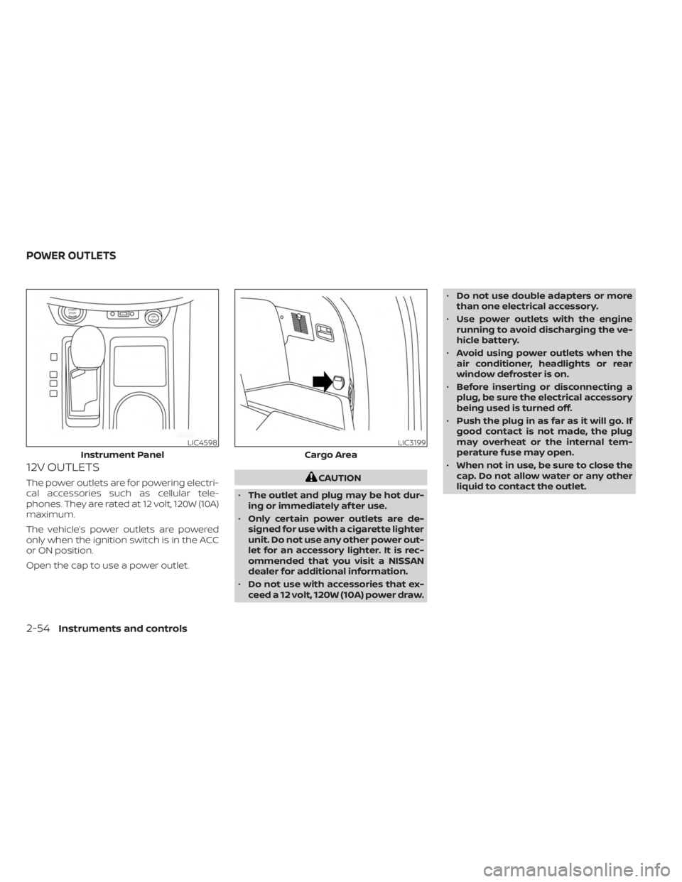
12V OUTLETS
The power outlets are for powering electri-
cal accessories such as cellular tele-
phones. They are rated at 12 volt, 120W (10A)
maximum.
The vehicle’s power outlets are powered
only when the ignition switch is in the ACC
or ON position.
Open the cap to use a power outlet.CAUTION
• The outlet and plug may be hot dur-
ing or immediately af ter use.
• Only certain power outlets are de-
signed for use with a cigarette lighter
unit. Do not use any other power out-
let for an accessory lighter. It is rec-
ommended that you visit a NISSAN
dealer for additional information.
• Do not use with accessories that ex-
ceed a 12 volt, 120W (10A) power draw. •
Do not use double adapters or more
than one electrical accessory.
• Use power outlets with the engine
running to avoid discharging the ve-
hicle battery.
• Avoid using power outlets when the
air conditioner, headlights or rear
window defroster is on.
• Before inserting or disconnecting a
plug, be sure the electrical accessory
being used is turned off.
• Push the plug in as far as it will go. If
good contact is not made, the plug
may overheat or the internal tem-
perature fuse may open.
• When not in use, be sure to close the
cap. Do not allow water or any other
liquid to contact the outlet.
LIC4598
Instrument Panel
LIC3199
Cargo Area
POWER OUTLETS
2-54Instruments and controls
Page 147 of 518
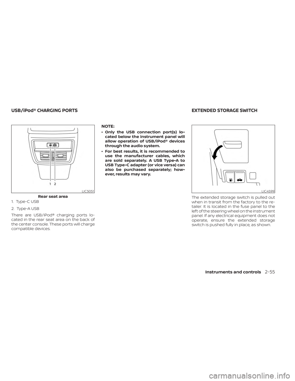
1. Type-C USB
2. Type-A USB
There are USB/iPod® charging ports lo-
cated in the rear seat area on the back of
the center console. These ports will charge
compatible devices.
NOTE:
• Only the USB connection port(s) lo-cated below the instrument panel will
allow operation of USB/iPod® devices
through the audio system.
• For best results, it is recommended to use the manufacturer cables, which
are sold separately. A USB Type-A to
USB Type-C adapter (or vice versa) can
also be purchased separately; how-
ever, results may vary.
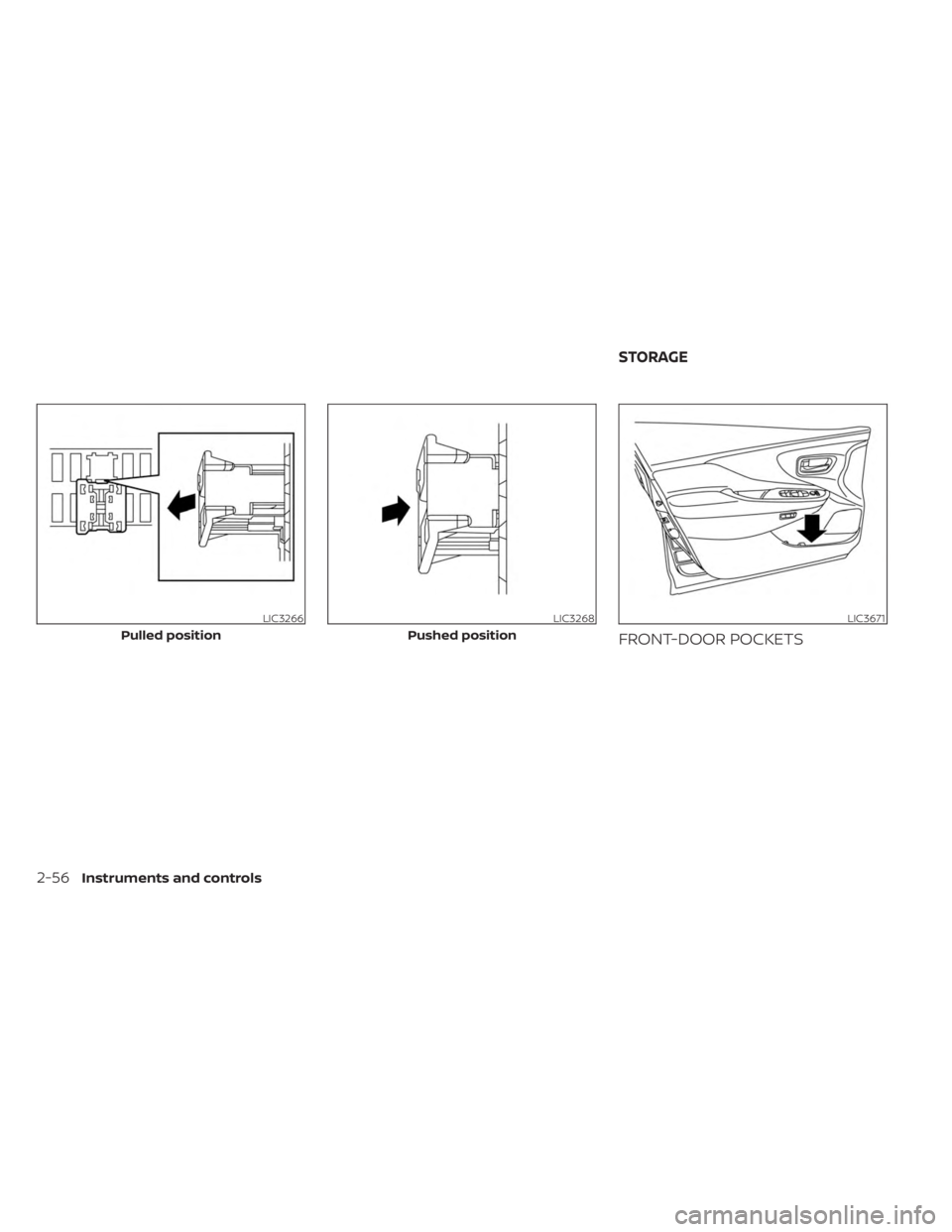
The extended storage switch is pulled out
when in transit from the factory to the re-
tailer. It is located in the fuse panel to the
lef t of the steering wheel on the instrument
panel. If any electrical equipment does not
operate, ensure the extended storage
switch is pushed fully in place, as shown.
LIC5051
Rear seat area
LIC4599
USB/iPod® CHARGING PORTS EXTENDED STORAGE SWITCH
Instruments and controls2-55
Page 148 of 518
FRONT-DOOR POCKETS
LIC3266
Pulled position
LIC3268
Pushed position
LIC3671
STORAGE
2-56Instruments and controls
Page 149 of 518
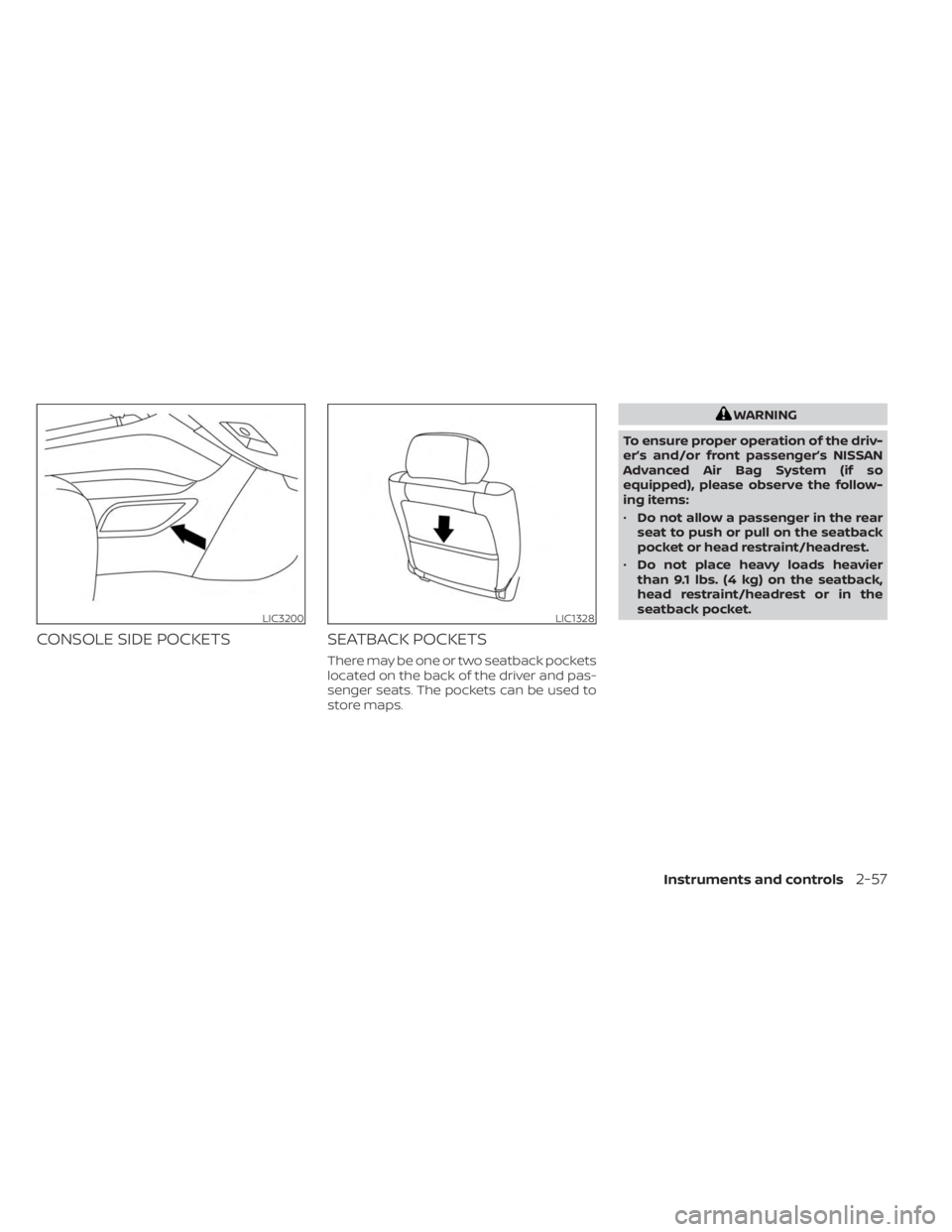
CONSOLE SIDE POCKETSSEATBACK POCKETS
There may be one or two seatback pockets
located on the back of the driver and pas-
senger seats. The pockets can be used to
store maps.
WARNING
To ensure proper operation of the driv-
er’s and/or front passenger’s NISSAN
Advanced Air Bag System (if so
equipped), please observe the follow-
ing items:
• Do not allow a passenger in the rear
seat to push or pull on the seatback
pocket or head restraint/headrest.
• Do not place heavy loads heavier
than 9.1 lbs. (4 kg) on the seatback,
head restraint/headrest or in the
seatback pocket.
LIC3200LIC1328
Instruments and controls2-57
Page 150 of 518
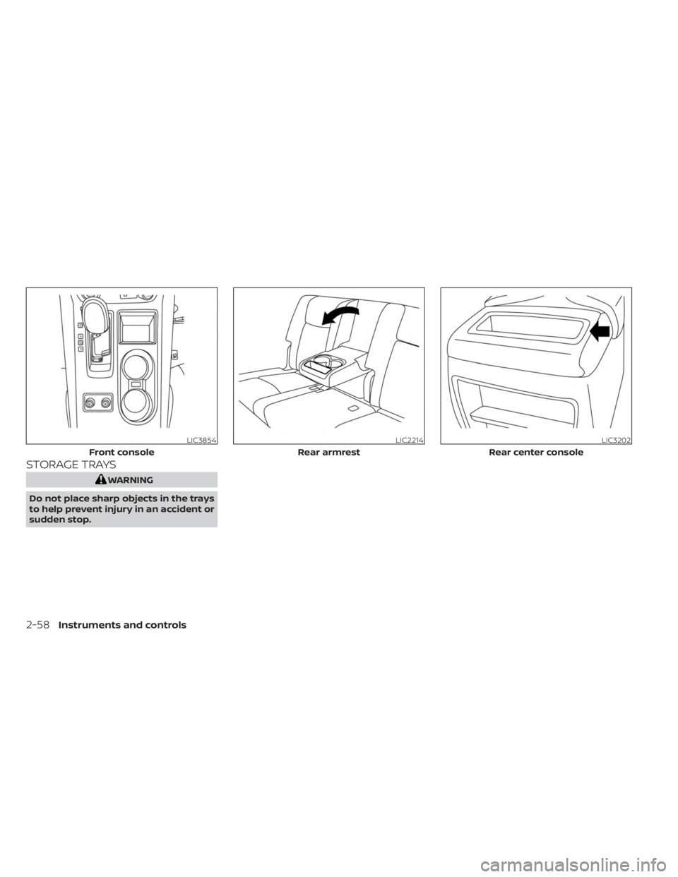
STORAGE TRAYS
WARNING
Do not place sharp objects in the trays
to help prevent injury in an accident or
sudden stop.
LIC3854
Front console
LIC2214
Rear armrest
LIC3202
Rear center console
2-58Instruments and controls