Unlock NISSAN NOTE 2006 User Guide
[x] Cancel search | Manufacturer: NISSAN, Model Year: 2006, Model line: NOTE, Model: NISSAN NOTE 2006Pages: 235, PDF Size: 2.29 MB
Page 107 of 235
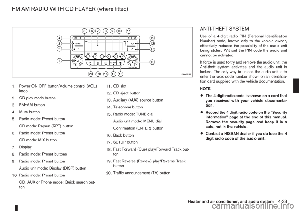
1.Power ON·OFF button/Volume control (VOL)
knob
2.CD play mode button
3.FM•AM button
4.Mute button
5.Radio mode: Preset button
CD mode: Repeat (RPT) button
6.Radio mode: Preset button
CD mode: MIX button
7.Display
8.Radio mode: Preset buttons
9.Radio mode: Preset button
Audio unit mode: Display (DISP) button
10.Radio mode: Preset button
CD, AUX or Phone mode: Quick search but-
ton11.CD slot
12.CD eject button
13.Auxiliary (AUX) source button
14.Telephone button
15.Radio mode: TUNE dial
Audio unit mode: MENU dial
Confirmation (ENTER) button
16.Back button
17.SETUP button
18.Fast Forward (Cue) play/Forward Track but-
ton
19.Fast Reverse (Review) play/Reverse Track
button
20.Traffic announcement (TA) button
ANTI-THEFT SYSTEM
Use of a 4-digit radio PIN (Personal Identification
Number) code, known only to the vehicle owner,
effectively reduces the possibility of the audio unit
being stolen. Without the PIN code the audio unit
cannot be activated.
If force is used to try and remove the audio unit, the
Anti-theft system activates and the audio unit is
locked. The only way to unlock the audio unit is to
enter the radio code number shown on an identifica-
tion card supplied with the vehicle documentation.
NOTE
•The 4 digit radio code is shown on a card that
you received with your vehicle documenta-
tion.
•Record the 4 digit radio code on the “Security
information” page at the end of this manual.
Remove the security page and keep it in a
safe, not in the vehicle.
•Contact a NISSAN dealer if you do lose the 4
digit radio code of the audio unit.
NAA1191
FM AM RADIO WITH CD PLAYER (where fitted)
Heater and air conditioner, and audio system4-23
Page 108 of 235
![NISSAN NOTE 2006 User Guide Unlocking the unit
If the battery supply to the vehicle is interrupted, the
audio unit will lock.
When the power is restored and the unit switched
on, the display will show [Radio Code:] and it will b NISSAN NOTE 2006 User Guide Unlocking the unit
If the battery supply to the vehicle is interrupted, the
audio unit will lock.
When the power is restored and the unit switched
on, the display will show [Radio Code:] and it will b](/img/5/56797/w960_56797-107.png)
Unlocking the unit
If the battery supply to the vehicle is interrupted, the
audio unit will lock.
When the power is restored and the unit switched
on, the display will show [Radio Code:] and it will be
unlocked when the codes have been entered cor-
rectly.
Unlocking procedure:
Read this section very carefully. It is important
that the instructions are followed precisely.
To unlock the audio unit, proceed as follows:
1. Turn the ignition switch to the Acc or ON posi-
tion.
2. [Radio Code:] is displayed along with four nu-
merical zero digits.
3. Press preset button <
j1 > the number of times
corresponding with the first digit of the radio
code.For example, if the radio code is 5169: for the
first digit, “5”, press the preset button <
j1 > five
times.
4. The second, third, and fourth digits of the radio
code must be entered, in the same way, only
now using preset buttons <
j2>,
For example, press <
j2 > once,
and
5. Press with a long press preset button <
j6>to
confirm the code. If you entered the code cor-
rectly the unit will switch on.
6. If the code is entered incorrectly a notification
message ([INCORRECT PIN]) and the number
of attempts left ([REMAINING TRIES: XX]) will
be shown.
After reading the message, press the
button to return to the entry screen and enter the
correct radio code.
– If the wrong code is entered after the third
attempt, the audio unit will lock for 60 min-
utes. The display will show a count down timer
from 60 to 0 (minutes). After 60 minutes enter
the correct radio code.
– If the wrong code is entered after eight sets
of three entries, the audio unit will lock per-
manently. Contact a NISSAN dealer for fur-
ther details.
AUDIO MAIN OPERATION
The audio unit operates when the ignition switch is
in Acc or ON position.
mPower ON/OFF button
Press the<>button to switch on the audio unit.
If the audio unit was switched off using the ignition
switch, it can also be switched on with the ignition
switch. The source that was playing immediately
before the unit was switched off will resume playing
and the volume will be set to the previous volume
level.
The audio unit can be switched off by pressing
<
>, or by turning the ignition switch to the “OFF”
or LOCK position.
mVolume (VOL) level control
Turn the
adjust the volume level.
The audio unit is equipped with a speed control vol-
ume function, this means that the audio system au-
tomatically adjusts the volume level in relation to
vehicle speed. For details, see “SPD VOL (Speed
volume) control” later in this section.
Mute button
Press the<>button to mute the sound and
[MUTE] appears in the display. To cancel the mode,
use any of the following options:
– Press<
>again.
NAA1192
4-24Heater and air conditioner, and audio system
Page 130 of 235
•Avoid starting off, accelerating or stopping sud-
denly.
•Avoid sharp turns or lane changes.
•Avoid sudden steering actions.
•Extra distance should be kept from the vehicle in
front.
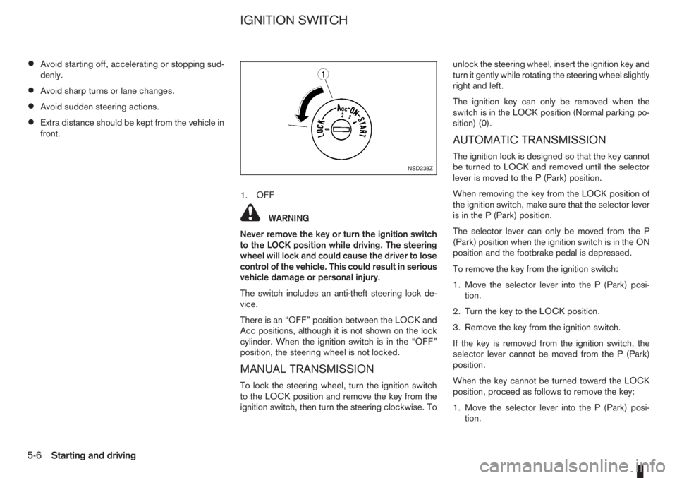
1.OFF
WARNING
Never remove the key or turn the ignition switch
to the LOCK position while driving. The steering
wheel will lock and could cause the driver to lose
control of the vehicle. This could result in serious
vehicle damage or personal injury.
The switch includes an anti-theft steering lock de-
vice.
There is an “OFF” position between the LOCK and
Acc positions, although it is not shown on the lock
cylinder. When the ignition switch is in the “OFF”
position, the steering wheel is not locked.
MANUAL TRANSMISSION
To lock the steering wheel, turn the ignition switch
to the LOCK position and remove the key from the
ignition switch, then turn the steering clockwise. Tounlock the steering wheel, insert the ignition key and
turn it gently while rotating the steering wheel slightly
right and left.
The ignition key can only be removed when the
switch is in the LOCK position (Normal parking po-
sition) (0).
AUTOMATIC TRANSMISSION
The ignition lock is designed so that the key cannot
be turned to LOCK and removed until the selector
lever is moved to the P (Park) position.
When removing the key from the LOCK position of
the ignition switch, make sure that the selector lever
is in the P (Park) position.
The selector lever can only be moved from the P
(Park) position when the ignition switch is in the ON
position and the footbrake pedal is depressed.
To remove the key from the ignition switch:
1. Move the selector lever into the P (Park) posi-
tion.
2. Turn the key to the LOCK position.
3. Remove the key from the ignition switch.
If the key is removed from the ignition switch, the
selector lever cannot be moved from the P (Park)
position.
When the key cannot be turned toward the LOCK
position, proceed as follows to remove the key:
1. Move the selector lever into the P (Park) posi-
tion.NSD238Z
IGNITION SWITCH
5-6Starting and driving
Page 131 of 235
2. Turn the key slightly in the ON direction.
3. Turn the key towards the LOCK position.
4. Remove the key.
STEERING LOCK
To lock the steering wheel
1. Turn the key to the LOCK position.
2. Remove the key from the ignition switch.
3. Turn the steering wheel 1/6 of a turn clockwise
from the straight up position.
To unlock the steering wheel
1. Insert the key into the ignition switch.
2. Gently turn the key while rotating the steering
wheel slightly right and left.
KEY POSITIONS
LOCK (Normal parking position) (0)
The ignition key can only be removed when in this
position.
The steering lock can only be locked in this position.
“OFF” (1)
The engine is turned off without locking the steering
wheel.
Acc (Accessories) (2)
This position activates electrical accessories, such
as the radio, when the engine is not running.
ON (Normal operating position) (3)
This position turns on the ignition system and elec-
trical accessories.
START (4)
The engine starter activates and the engine will start.
As soon as the engine has started, release the key
immediately. It will return to the ON position.
NISSAN ANTI-THEFT SYSTEM (NATS)
The NISSAN Anti Theft System (NATS)* will stop
the engine if someone tries to start the engine with-
out using the registered NATS key.
* Immobilizer
If you failed to start the engine using the NATS Key,
turn the ignition knob to the LOCK position, wait for
5 seconds and turn the key to the START position
again to start the engine.
For additional information, see “Security system” in
the “3. Pre-driving checks and adjustments” sec-
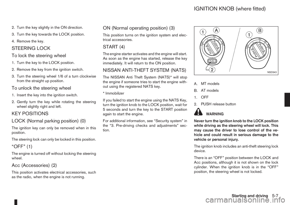
tion.A.MT models
B.AT models
1.OFF
2.PUSH release button
WARNING
Never turn the ignition knob to the LOCK position
while driving as the steering wheel will lock. This
may cause the driver to lose control of the ve-
hicle and could result in serious damage to the
vehicle or personal injury.
The ignition knob includes an anti-theft steering lock
device.
There is an “OFF” position between the LOCK and
Acc positions, although it is not shown on the lock
cylinder. When the ignition knob is in the “OFF”
position, the steering wheel is not locked.
NSD343
IGNITION KNOB (where fitted)
Starting and driving5-7
Page 132 of 235
CAUTION
•Make sure you carry the Intelligent Key with
you when operating the vehicle.
•Never leave the Intelligent Key inside the ve-
hicle when you leave the vehicle.
•If the Intelligent Key is too far away from the
driver, the vehicle may not start.
MANUAL TRANSMISSION
The ignition lock is designed so that the knob can
ONLY be turned to the LOCK position when the
PUSH release button has first been depressed.
NOTE
•The ignition knob warning light () blinks
and the buzzer sounds twice when the igni-
tion knob is turned to the “OFF” position. De-
press the PUSH release button
j2 , then turn
the ignition knob to the LOCK position. See
“Warning/indicator lights and audible
reminders” in the “2. Instruments and
controls” section for further details regarding
the functionality of the ignition knob warning
light.
•When the emergency key is being used, the
PUSH release buttonj2 must be depressed
in order to turn the ignition knob to the LOCK
position although the ignition knob warning
light (
) will not blink and the buzzer will not
sound.
AUTOMATIC TRANSMISSION
The ignition knob is designed so that it cannot be
turned to the LOCK position until the selector lever
is moved to the P (Park) position. The selector lever
can only be moved from the P (Park) position when
the ignition knob is in the ON position and the
footbrake pedal is depressed.
NOTE
The ignition knob warning light (
) blinks and a
buzzer sounds twice when the ignition knob is
turned to the “OFF” position. Make sure that the
selector lever is in the P (Park) position, then turn
the ignition knob to the LOCK position. See
“Warning/indicator lights and audible reminders”
in the “2. Instruments and controls” section for
further details regarding the functionality of the
ignition knob warning light.
STEERING LOCK
To lock the steering wheel
In the LOCK position, turn the steering wheel 1/6 of
a turn from the straight up position.
To unlock the steering wheel
Depress the brake pedal, push the ignition knob and
turn it towards the Acc position while gently rotating
the steering wheel right or left.
IGNITION KNOB POSITION
LOCK (Normal parking position) (0)
The steering lock can be only be locked from this
position.
“OFF” (1)
The engine can be turned off without locking the
steering wheel.
Acc (Accessories) (2)
This position activates electrical accessories, such
as the radio, when the engine is not running.
ON (Normal operating position) (3)
This position turns on the ignition system and the
electrical accessories.
START (4)
The engine starter activates and the engine will start.
As soon as the engine has started, release the knob
immediately. It will return to the ON position.
5-8Starting and driving
Page 133 of 235
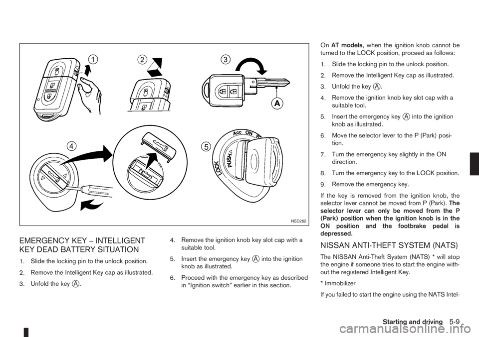
EMERGENCY KEY – INTELLIGENT
KEY DEAD BATTERY SITUATION
1.Slide the locking pin to the unlock position.
2.Remove the Intelligent Key cap as illustrated.
3.Unfold the key
jA.4.Remove the ignition knob key slot cap with a
suitable tool.
5.Insert the emergency key
jA into the ignition
knob as illustrated.
6.Proceed with the emergency key as described
in “Ignition switch” earlier in this section.OnAT models, when the ignition knob cannot be
turned to the LOCK position, proceed as follows:
1.Slide the locking pin to the unlock position.
2.Remove the Intelligent Key cap as illustrated.
3.Unfold the key
jA.
4.Remove the ignition knob key slot cap with a
suitable tool.
5.Insert the emergency key
jA into the ignition
knob as illustrated.
6.Move the selector lever to the P (Park) posi-
tion.
7.Turn the emergency key slightly in the ON
direction.
8.Turn the emergency key to the LOCK position.
9.Remove the emergency key.
If the key is removed from the ignition knob, the
selector lever cannot be moved from P (Park).The
selector lever can only be moved from the P
(Park) position when the ignition knob is in the
ON position and the footbrake pedal is
depressed.
NISSAN ANTI-THEFT SYSTEM (NATS)
The NISSAN Anti-Theft System (NATS) * will stop
the engine if someone tries to start the engine with-
out the registered Intelligent Key.
* Immobilizer
If you failed to start the engine using the NATS Intel-
NSD262
Starting and driving5-9
Page 193 of 235
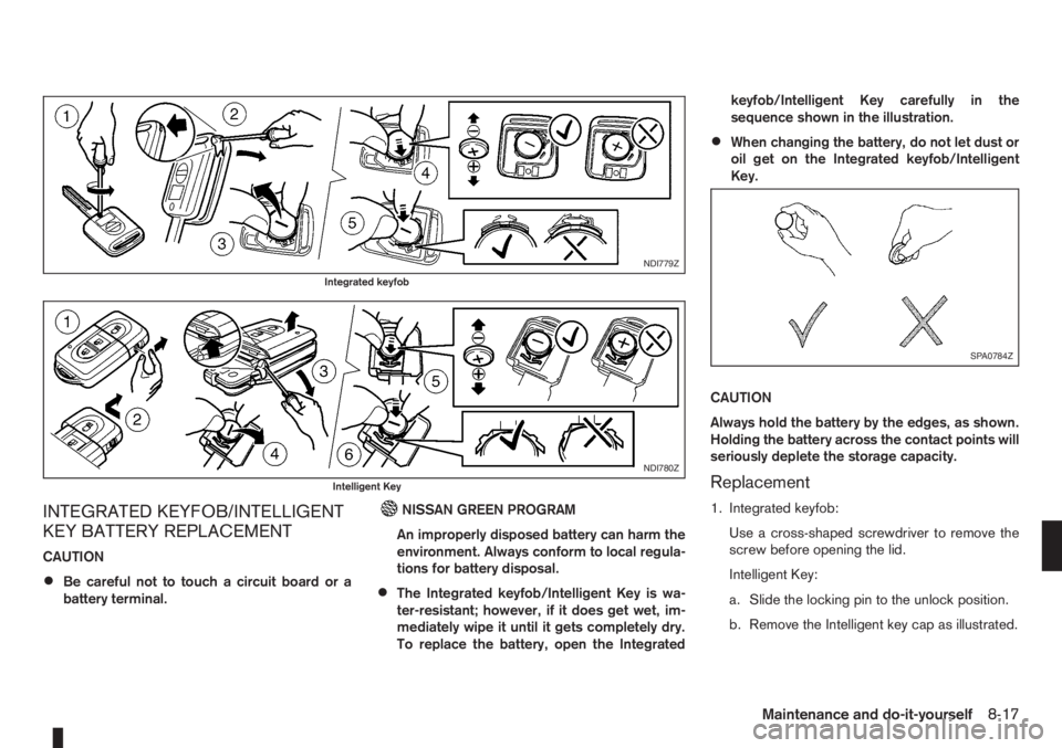
INTEGRATED KEYFOB/INTELLIGENT
KEY BATTERY REPLACEMENT
CAUTION
•Be careful not to touch a circuit board or a
battery terminal.
NISSAN GREEN PROGRAM
An improperly disposed battery can harm the
environment. Always conform to local regula-
tions for battery disposal.
•The Integrated keyfob/Intelligent Key is wa-
ter-resistant; however, if it does get wet, im-
mediately wipe it until it gets completely dry.
To replace the battery, open the Integratedkeyfob/Intelligent Key carefully in the
sequence shown in the illustration.
•When changing the battery, do not let dust or
oil get on the Integrated keyfob/Intelligent
Key.
CAUTION
Always hold the battery by the edges, as shown.
Holding the battery across the contact points will
seriously deplete the storage capacity.
Replacement
1. Integrated keyfob:
Use a cross-shaped screwdriver to remove the
screw before opening the lid.
Intelligent Key:
a. Slide the locking pin to the unlock position.
b. Remove the Intelligent key cap as illustrated.
NDI779Z
Integrated keyfob
NDI780Z
Intelligent Key
SPA0784Z
Maintenance and do-it-yourself8-17
Page 222 of 235
– Trailer brakes ................................................................ 5-25
C
Capacities and recommended fuel/lubricants ......................... 9-2
– Fuel recommendation ...................................................... 9-4
Car phone or CB radio ........................................................ 4-39
Care when driving ................................................................. 5-5
Changing
– Changing engine coolant ................................................. 8-6
– Changing engine oil ......................................................... 8-9
– Changing engine oil filter ............................................... 8-11
– Changing tyres and wheels ........................................... 8-31
Checking
– Checking brake pedal ................................................... 8-13
– Checking engine coolant level ......................................... 8-6
– Checking engine oil level ................................................. 8-9
– Checking handbrake ..................................................... 8-13
Child restraint anchorage (top tether) .................................. 1-23
Child restraints .................................................................... 1-16
– Installation on front passenger seat ................................ 1-19
– Installation on rear seats ................................................ 1-20
Child safety ........................................................................... 1-7
Cleaning
– Alloy wheels .................................................................... 7-3
– Chrome parts .................................................................. 7-3
– Exterior ............................................................................ 7-2
– Glass ....................................................................... 7-3, 7-4
– Interior ............................................................................ 7-3
– Plastic parts .................................................................... 7-4
– Removing spots ............................................................... 7-2
– Underbody ...................................................................... 7-3
Clock (digital) ........................................................................ 2-5
Clutch fluid .......................................................................... 8-13
Cold weather driving ........................................................... 5-31Coolant
– Changing engine coolant ................................................. 8-6
– Checking engine coolant level ......................................... 8-6
– Engine coolant ............................................................... 5-31
– Engine cooling system ..................................................... 8-6
Corrosion protection .................................................... 5-32, 7-4
– Environmental factors ...................................................... 7-4
Cruise control system .......................................................... 5-18
Cruise control system operations ......................................... 5-19
D
Defogger switch
– Outside mirror defogger ................................................ 2-15
– Rear window defogger .................................................. 2-15
Diesel particulate filter ........................................................... 5-5
Dimensions ........................................................................... 9-6
Door
– Back door lock ................................................................ 3-8
– Child safety rear door lock ............................................... 3-8
– Door locks ....................................................................... 3-6
– Emergency situation – Super Lock system ....................... 3-6
– Locking/unlocking with emergency key or key (vehicle dead
battery situation) .............................................................. 3-7
– Power door lock switch ................................................... 3-7
– Super Lock system .......................................................... 3-6
Drive belts ........................................................................... 8-18
Driving
– Care when driving ........................................................... 5-5
– Cold weather driving ..................................................... 5-31
– Driving on wet road ......................................................... 5-5
– Driving the vehicle ......................................................... 5-11
– Driving under winter conditions ........................................ 5-5
– Driving with automatic transmission ............................... 5-12
– Driving with manual transmission ................................... 5-11
– Precautions when starting and driving .............................. 5-3
10-2Index
Page 224 of 235
I
Ignition
– Ignition knob (Intelligent Key equipped models) ................ 5-7
– Ignition switch ................................................................. 5-6
Immobilizer
– NATS immobilizer radio approval number ......................... 9-8
– NISSAN Anti-Theft System (NATS) ................................. 3-9
Indicator lights
– Warning/indicator lights and audible reminders ................ 2-7
Injured persons ..................................................................... 1-7
Inside rear-view mirror ......................................................... 3-12
Instrument and control layout
– LHD models .................................................................... 0-5
– RHD models .................................................................... 0-7
Integrated keyfob (remote control system) ............................. 3-3
– Battery replacement ...................................................... 8-17
– Ignition switch ................................................................. 5-6
– Keyfob operation failure ................................................... 3-4
– Locking the doors ............................................................ 3-3
– Switching from convenience mode to anti-hijack mode ..... 3-4
– Unlocking the doors – Anti hijack mode ........................... 3-4
– Unlocking the doors – Convenience mode ....................... 3-4
Intelligent Key system ............................................................ 3-5
– Battery replacement ...................................................... 8-17
– Emergency key – Intelligent Key dead battery situation ..... 5-9
– Ignition knob .................................................................... 5-7
– Locking/unlocking ........................................................... 3-5
– Starting the engine .......................................................... 3-6
Interior lights .............................................................. 2-27, 8-24
– Luggage compartment light ........................................... 2-28
– Map light ....................................................................... 2-28
iPod® player operation ........................................................ 4-30
ISOFIX system .................................................................... 1-22JJump-starting ................................................................ 6-9, 8-16
K
Key
– Ignition knob positions ..................................................... 5-8
– Intelligent Key system ...................................................... 3-5
– Key positions (Ignition switch) .......................................... 5-7
– Key(s) ............................................................................. 3-2
– Remote keyless entry system ........................................... 3-3
L
Light
– Exterior lights ................................................................. 8-24
– Fog light switch ............................................................. 2-17
– Hazard warning flasher switch ....................................... 2-19
– Headlight aiming control switch ..................................... 2-18
– Headlight and turn signal switch .................................... 2-16
– Headlight cleaner .......................................................... 2-14
– Headlight switch ............................................................ 2-16
– Headlights ..................................................................... 8-23
– Interior lights ........................................................ 2-27, 8-24
– Light locations ............................................................... 8-25
– Luggage compartment ................................................... 2-28
– Map light ....................................................................... 2-28
– Room light ..................................................................... 2-27
– Turn signal switch .......................................................... 2-17
Lock
– Back door lock ................................................................ 3-8
– Child safety rear door lock ............................................... 3-8
– Doors .............................................................................. 3-6
– Keys ................................................................................ 3-2
10-4Index