cool NISSAN NOTE 2006 Owners Manual
[x] Cancel search | Manufacturer: NISSAN, Model Year: 2006, Model line: NOTE, Model: NISSAN NOTE 2006Pages: 235, PDF Size: 2.29 MB
Page 15 of 235
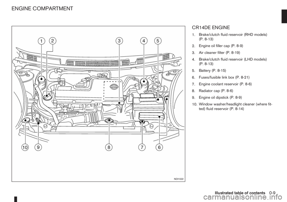
CR14DE ENGINE
1.Brake/clutch fluid reservoir (RHD models)
(P. 8-13)
2.Engine oil filler cap (P. 8-9)
3.Air cleaner filter (P. 8-19)
4.Brake/clutch fluid reservoir (LHD models)
(P. 8-13)
5.Battery (P. 8-15)
6.Fuses/fusible link box (P. 8-21)
7.Engine coolant reservoir (P. 8-6)
8.Radiator cap (P. 8-6)
9.Engine oil dipstick (P. 8-9)
10.Window washer/headlight cleaner (where fit-
ted) fluid reservoir (P. 8-14)
NDI1022
ENGINE COMPARTMENT
Illustrated table of contents0-9
Page 16 of 235
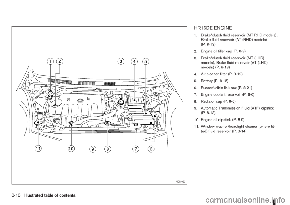
HR16DE ENGINE
1.Brake/clutch fluid reservoir (MT RHD models),
Brake fluid reservoir (AT (RHD) models)
(P. 8-13)
2.Engine oil filler cap (P. 8-9)
3.Brake/clutch fluid reservoir (MT (LHD)
models), Brake fluid reservoir (AT (LHD)
models) (P. 8-13)
4.Air cleaner filter (P. 8-19)
5.Battery (P. 8-15)
6.Fuses/fusible link box (P. 8-21)
7.Engine coolant reservoir (P. 8-6)
8.Radiator cap (P. 8-6)
9.Automatic Transmission Fluid (ATF) dipstick
(P. 8-13)
10.Engine oil dipstick (P. 8-9)
11.Window washer/headlight cleaner (where fit-
ted) fluid reservoir (P. 8-14)
NDI1023
0-10Illustrated table of contents
Page 17 of 235
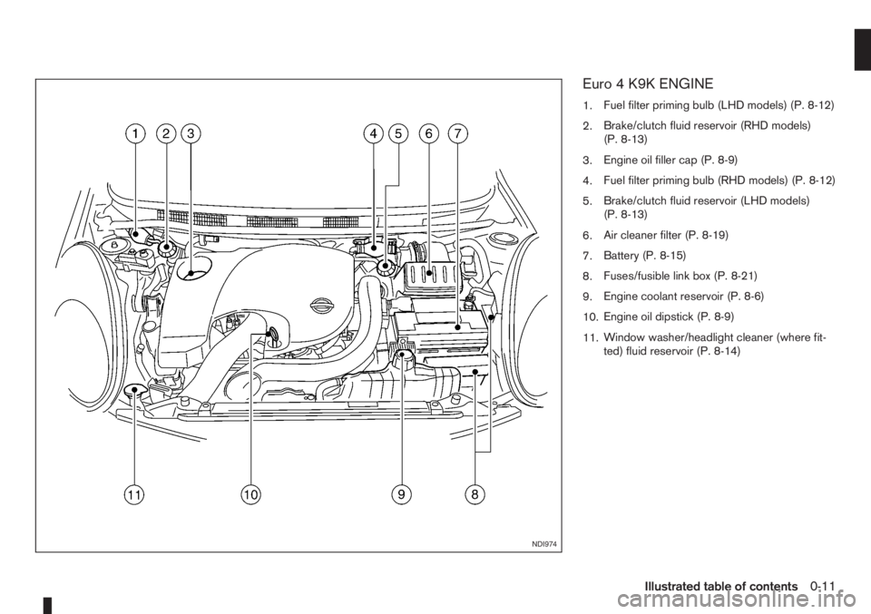
Euro 4 K9K ENGINE
1.Fuel filter priming bulb (LHD models) (P. 8-12)
2.Brake/clutch fluid reservoir (RHD models)
(P. 8-13)
3.Engine oil filler cap (P. 8-9)
4.Fuel filter priming bulb (RHD models) (P. 8-12)
5.Brake/clutch fluid reservoir (LHD models)
(P. 8-13)
6.Air cleaner filter (P. 8-19)
7.Battery (P. 8-15)
8.Fuses/fusible link box (P. 8-21)
9.Engine coolant reservoir (P. 8-6)
10.Engine oil dipstick (P. 8-9)
11.Window washer/headlight cleaner (where fit-
ted) fluid reservoir (P. 8-14)
NDI974
Illustrated table of contents0-11
Page 18 of 235
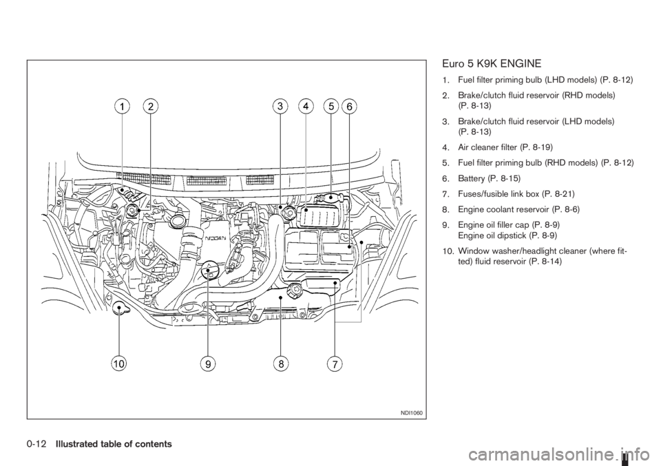
Euro 5 K9K ENGINE
1.Fuel filter priming bulb (LHD models) (P. 8-12)
2.Brake/clutch fluid reservoir (RHD models)
(P. 8-13)
3.Brake/clutch fluid reservoir (LHD models)
(P. 8-13)
4.Air cleaner filter (P. 8-19)
5.Fuel filter priming bulb (RHD models) (P. 8-12)
6.Battery (P. 8-15)
7.Fuses/fusible link box (P. 8-21)
8.Engine coolant reservoir (P. 8-6)
9.Engine oil filler cap (P. 8-9)
Engine oil dipstick (P. 8-9)
10.Window washer/headlight cleaner (where fit-
ted) fluid reservoir (P. 8-14)
NDI1060
0-12Illustrated table of contents
Page 49 of 235
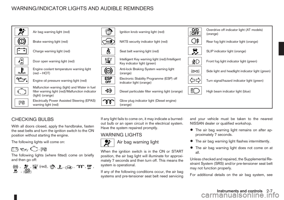
Air bag warning light (red)Ignition knob warning light (red)Overdrive off indicator light (AT models)
(orange)
Brake warning light (red)NATS security indicator light (red)Rear fog light indicator light (orange)
Charge warning light (red)Seat belt warning light (red)SLIP indicator light (orange)
Door open warning light (red)Intelligent Key warning light (red)/Intelligent
Key indicator light (green)Front fog light indicator light (green)
Engine coolant temperature warning light
(red – HOT)Anti-lock Braking System warning light
(orange)Side light and headlight indicator light (green)
Engine oil pressure warning light (red)Electronic Stability Programme (ESP) off
indicator light (orange)Turn signal/hazard indicator light (green)
Malfunction warning (light) and Water in fuel
filter warning light (red)/Malfunction indicator
(light) (orange)Diesel particulate filter warning light (orange)High beam indicator light (blue)
Electrically Power Assisted Steering (EPAS)
warning light (red)Glow plug indicator light (Diesel engine)
(orange)
CHECKING BULBS
With all doors closed, apply the handbrake, fasten
the seat belts and turn the ignition switch to the ON
position without starting the engine.
The following lights will come on:
,,,
The following lights (where fitted) come on briefly
and then go off:
,,(red),,,,,,,
If any light fails to come on, it may indicate a burned-
out bulb or an open circuit in the electrical system.
Have the system repaired promptly.
WARNING LIGHTS
Air bag warning light
When the ignition switch is in the ON or START
position, the air bag light will illuminate for approxi-
mately 7 seconds and then turn off. This means the
system is operational.
If any of the following conditions occur, the air bag
systems and pre-tensioner seat belt need servicingand your vehicle must be taken to the nearest
NISSAN dealer or qualified workshop.
•The air bag warning light remains on after ap-
proximately 7 seconds.
•The air bag warning light flashes intermittently.
•The air bag warning light does not come on at
all.
Unless checked and repaired, the Supplemental Re-
straint System (SRS) and/or pre-tensioner seat belt
may not function properly.
For additional details on the air bag system, see
WARNING/INDICATOR LIGHTS AND AUDIBLE REMINDERS
Instruments and controls2-7
Page 50 of 235
“Supplemental Restraint System (air bag system)”
in the “1. Safety — seats, seat belts and supple-
mental restraint system” section.
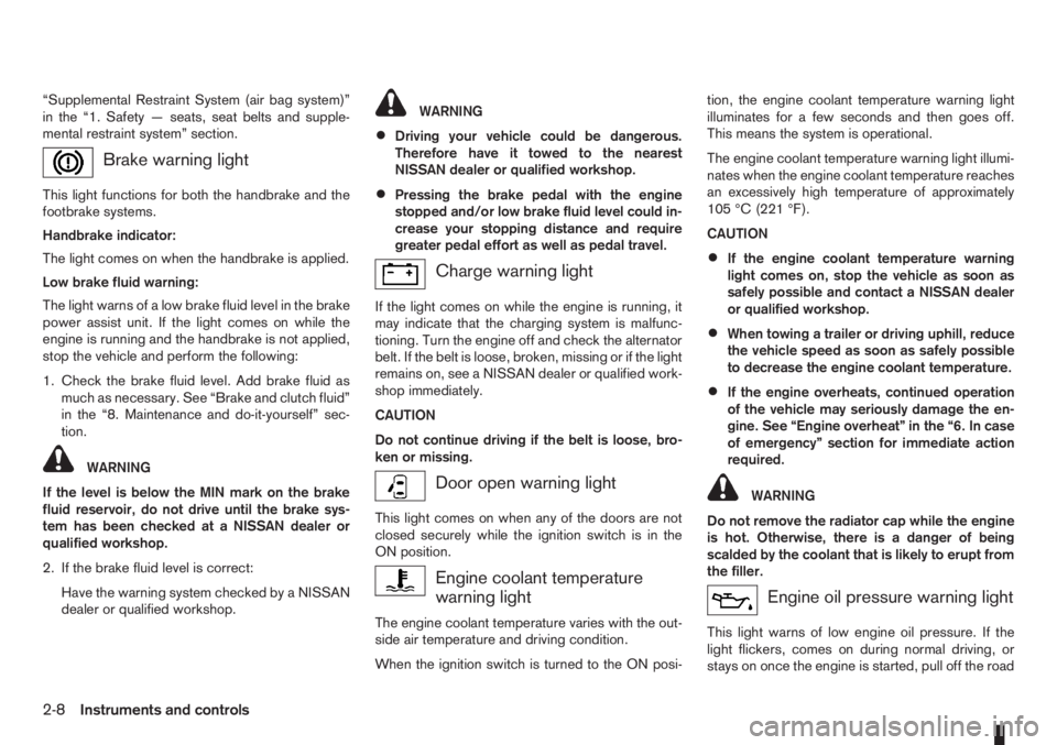
Brake warning light
This light functions for both the handbrake and the
footbrake systems.
Handbrake indicator:
The light comes on when the handbrake is applied.
Low brake fluid warning:
The light warns of a low brake fluid level in the brake
power assist unit. If the light comes on while the
engine is running and the handbrake is not applied,
stop the vehicle and perform the following:
1. Check the brake fluid level. Add brake fluid as
much as necessary. See “Brake and clutch fluid”
in the “8. Maintenance and do-it-yourself” sec-
tion.
WARNING
If the level is below the MIN mark on the brake
fluid reservoir, do not drive until the brake sys-
tem has been checked at a NISSAN dealer or
qualified workshop.
2. If the brake fluid level is correct:
Have the warning system checked by a NISSAN
dealer or qualified workshop.
WARNING
•Driving your vehicle could be dangerous.
Therefore have it towed to the nearest
NISSAN dealer or qualified workshop.
•Pressing the brake pedal with the engine
stopped and/or low brake fluid level could in-
crease your stopping distance and require
greater pedal effort as well as pedal travel.
Charge warning light
If the light comes on while the engine is running, it
may indicate that the charging system is malfunc-
tioning. Turn the engine off and check the alternator
belt. If the belt is loose, broken, missing or if the light
remains on, see a NISSAN dealer or qualified work-
shop immediately.
CAUTION
Do not continue driving if the belt is loose, bro-
ken or missing.
Door open warning light
This light comes on when any of the doors are not
closed securely while the ignition switch is in the
ON position.
Engine coolant temperature
warning light
The engine coolant temperature varies with the out-
side air temperature and driving condition.
When the ignition switch is turned to the ON posi-tion, the engine coolant temperature warning light
illuminates for a few seconds and then goes off.
This means the system is operational.
The engine coolant temperature warning light illumi-
nates when the engine coolant temperature reaches
an excessively high temperature of approximately
105 °C (221 °F).
CAUTION
•If the engine coolant temperature warning
light comes on, stop the vehicle as soon as
safely possible and contact a NISSAN dealer
or qualified workshop.
•When towing a trailer or driving uphill, reduce
the vehicle speed as soon as safely possible
to decrease the engine coolant temperature.
•If the engine overheats, continued operation
of the vehicle may seriously damage the en-
gine. See “Engine overheat” in the “6. In case
of emergency” section for immediate action
required.
WARNING
Do not remove the radiator cap while the engine
is hot. Otherwise, there is a danger of being
scalded by the coolant that is likely to erupt from
the filler.
Engine oil pressure warning light
This light warns of low engine oil pressure. If the
light flickers, comes on during normal driving, or
stays on once the engine is started, pull off the road
2-8Instruments and controls
Page 63 of 235
•Before inserting or disconnecting a plug, be
sure to turn off the power switch of the elec-
trical accessory being used or the Acc power
of the vehicle.
•Fully push the plug in. If insufficient contact is
made, the plug may overheat or the respec-
tive fuse may blow.
WARNING
Take care as the power outlet and plug may be
hot during or immediately after use.
GLOVE BOX
WARNING
•The glove box storage should not be used
while driving so that full attention may be given
to the driving operation.
•Keep the glove box lid closed while driving to
prevent injury in an accident or a sudden stop.
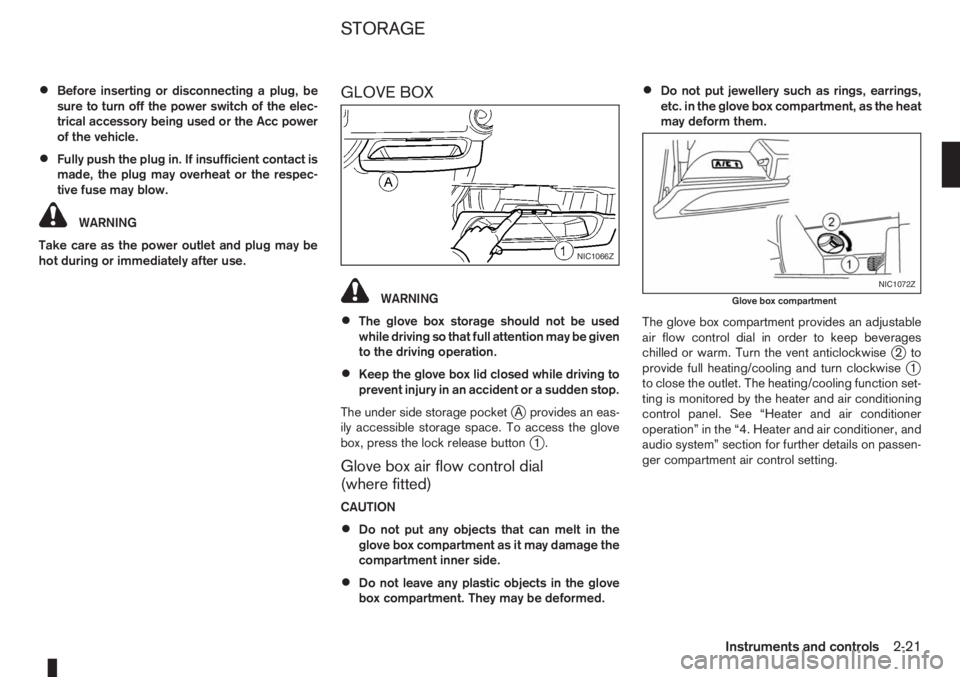
The under side storage pocket
jA provides an eas-
ily accessible storage space. To access the glove
box, press the lock release button
j1.
Glove box air flow control dial
(where fitted)
CAUTION
•Do not put any objects that can melt in the
glove box compartment as it may damage the
compartment inner side.
•Do not leave any plastic objects in the glove
box compartment. They may be deformed.
•Do not put jewellery such as rings, earrings,
etc. in the glove box compartment, as the heat
may deform them.
The glove box compartment provides an adjustable
air flow control dial in order to keep beverages
chilled or warm. Turn the vent anticlockwise
j2to
provide full heating/cooling and turn clockwisej1
to close the outlet. The heating/cooling function set-
ting is monitored by the heater and air conditioning
control panel. See “Heater and air conditioner
operation” in the “4. Heater and air conditioner, and
audio system” section for further details on passen-
ger compartment air control setting.
NIC1066Z
NIC1072Z
Glove box compartment
STORAGE
Instruments and controls2-21
Page 87 of 235
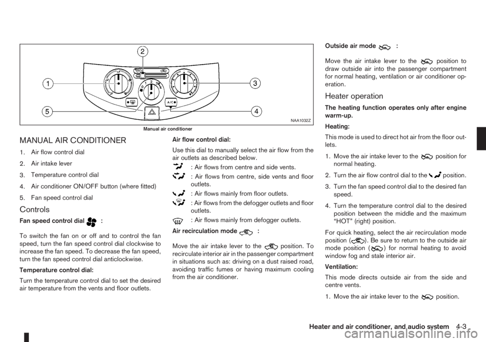
MANUAL AIR CONDITIONER
1.Air flow control dial
2.Air intake lever
3.Temperature control dial
4.Air conditioner ON/OFF button (where fitted)
5.Fan speed control dial
Controls
Fan speed control dialm:
To switch the fan on or off and to control the fan
speed, turn the fan speed control dial clockwise to
increase the fan speed. To decrease the fan speed,
turn the fan speed control dial anticlockwise.
Temperature control dial:
Turn the temperature control dial to set the desired
air temperature from the vents and floor outlets.Air flow control dial:
Use this dial to manually select the air flow from the
air outlets as described below.
: Air flows from centre and side vents.
: Air flows from centre, side vents and floor
outlets.
: Air flows mainly from floor outlets.
: Air flows from the defogger outlets and floor
outlets.
: Air flows mainly from defogger outlets.
Air recirculation mode
m:
Move the air intake lever to the
position. To
recirculate interior air in the passenger compartment
in situations such as: driving on a dust raised road,
avoiding traffic fumes or having maximum cooling
from the air conditioner.Outside air mode
m:
Move the air intake lever to the
position to
draw outside air into the passenger compartment
for normal heating, ventilation or air conditioner op-
eration.
Heater operation
The heating function operates only after engine
warm-up.
Heating:
This mode is used to direct hot air from the floor out-
lets.
1. Move the air intake lever to the
position for
normal heating.
2. Turn the air flow control dial to the
position.
3. Turn the fan speed control dial to the desired fan
speed.
4. Turn the temperature control dial to the desired
position between the middle and the maximum
“HOT” (right) position.
For quick heating, select the air recirculation mode
position (
). Be sure to return to the outside air
mode position () for normal heating to avoid
window fog and stale interior air.
Ventilation:
This mode directs outside air from the side and
centre vents.
1. Move the air intake lever to the
position.
NAA1032Z
Manual air conditioner
Heater and air conditioner, and audio system4-3
Page 88 of 235
2. Turn the air flow control dial to theposition.
3. Turn the fan speed control dial to the desired fan
speed.
4. Turn the temperature control dial to the desired
position.
Defrosting or defogging:
This mode is used to defrost/defog the windows.
1. Move the air intake lever to the
position.
2. Turn the air flow control dial to the
position.
3. Turn the fan speed control dial to speed position
2 or above.
4. Turn the temperature control dial to the desired
position between the middle and the maximum
“HOT” (right) position.
To quickly defrost/defog the windscreen, turn the
fan speed control dial to the maximum position and
the temperature control dial to the maximum “HOT”
(right) position.
Heating and defogging:
This mode heats the interior and defogs the wind-
screen.
1. Move the air intake lever to outside air mode
position (
).
2. Turn the air flow control dial to the
position.
3. Turn the fan speed control dial to speed position
2 or above.4. Turn the temperature control dial between the
middle and the maximum “HOT” (right) position.
Air conditioner operation (where fitted)
Start the engine, turn the fan speed control dial to
the desired fan speed and press the A/C button to
activate the air conditioner. When the air conditioner
is on, cooling and dehumidifying functions will be
added to the heater operation. To switch off the air
conditioner, press the button again.
NOTE
The air conditioner cooling function operates only
when the engine is running.
Cooling:
This mode is used to cool and dehumidify.
1. Move the air intake lever to outside air mode
position (
).
2. Turn the air flow control dial to the
position.
3. Turn the fan speed control dial to the desired fan
speed.
4. Press thebutton and the indicator light
will come on.
5. Turn the temperature control dial to the desired
position.
For quick cooling when the outside temperature is
high, select the air recirculation mode position
(
). Be sure to return to the outside air mode
position () to avoid windows from fogging-up
and interior air from becoming stale.NOTE
A visible mist may be seen coming from the vents
in hot, humid conditions as the air is cooled rap-
idly. This does not indicate a malfunction.
Dehumidified heating:
This mode is used to heat and dehumidify.
1. Move the air intake lever to outside air mode
position (
).
2. Turn the air flow control dial to the
position.
3. Turn on the fan speed control dial to the desired
fan speed.
4. Press thebutton and the indicator light
will come on.
5. Turn the temperature control dial to the desired
position.
Dehumidified defogging:
This mode is used to defog the windows and dehu-
midify.
1. Move the air intake lever to outside air mode
position (
).
2. Turn the air flow control dial to the
position.
3. Turn the fan speed control dial to the desired fan
speed.
4. Press thebutton and the indicator light
will come on.
5. Turn the temperature control dial to the desired
position.
4-4Heater and air conditioner, and audio system
Page 89 of 235
Operating tips
•In order to improve the heater operation, clear
the snow and ice from the wiper blade and air
inlet in front of the windscreen.
•After parking in the sun, drive for two or three
minutes with the windows open to vent hot air
from the passenger compartment. Then close
the windows to allow the acceleration of the air
conditioner’s cooling operation.
•Keep the windows closed while the air condi-
tioner is operating.
•The air conditioning system should be operated
for about 10 minutes, at least once a month. This
helps prevent damage to the system due to lack
of lubrication.
•If the coolant temperature warning light comes
on, turn the air conditioner off. For additional
information, see “Engine overheat” in the “6. In
case of emergency” section.
•If the engine coolant reaches an extremely high
temperature, the air conditioning system will au-
tomatically turn off. This may happen for example
if the engine runs at idle speed for a long time on
a hot day.
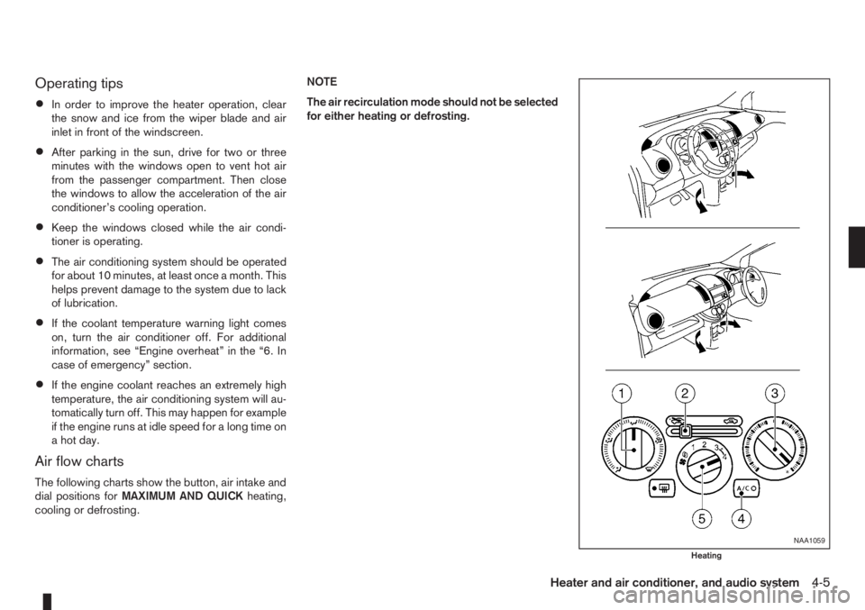
Air flow charts
The following charts show the button, air intake and
dial positions forMAXIMUM AND QUICKheating,
cooling or defrosting.NOTE
The air recirculation mode should not be selected
for either heating or defrosting.
NAA1059
Heating
Heater and air conditioner, and audio system4-5