fuel NISSAN NOTE 2007 Owners Manual
[x] Cancel search | Manufacturer: NISSAN, Model Year: 2007, Model line: NOTE, Model: NISSAN NOTE 2007Pages: 235, PDF Size: 2.29 MB
Page 9 of 235
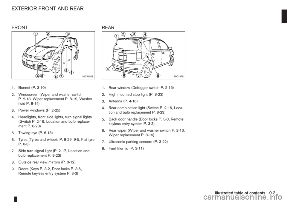
FRONT
1.Bonnet (P. 3-10)
2.Windscreen (Wiper and washer switch
P. 2-13, Wiper replacement P. 8-19, Washer
fluid P. 8-14)
3.Power windows (P. 2-25)
4.Headlights, front side lights, turn signal lights
(Switch P. 2-16, Location and bulb replace-
ment P. 8-23)
5.Towing eye (P. 6-13)
6.Tyres (Tyres and wheels P. 8-29, 9-5, Flat tyre
P. 6-3)
7.Side turn signal light (P. 2-17, Location and
bulb replacement P. 8-23)
8.Outside rear view mirrors (P. 3-12)
9.Doors (Keys P. 3-2, Door locks P. 3-6,
Remote keyless entry system P. 3-3)
REAR
1.Rear window (Defogger switch P. 2-15)
2.High mounted stop light (P. 8-23)
3.Antenna (P. 4-16)
4.Rear combination light (Switch P. 2-16, Loca-
tion and bulb replacement P. 8-23)
5.Back door handle (Door locks P. 3-8, Remote
keyless entry system P. 3-3)
6.Rear wiper (Wiper and washer switch P. 2-13,
Wiper replacement P. 8-19)
7.Ultrasonic parking sensors (P. 3-22)
8.Fuel filler lid (P. 3-11)
NIC1104ZNIC1475
EXTERIOR FRONT AND REAR
Illustrated table of contents0-3
Page 11 of 235
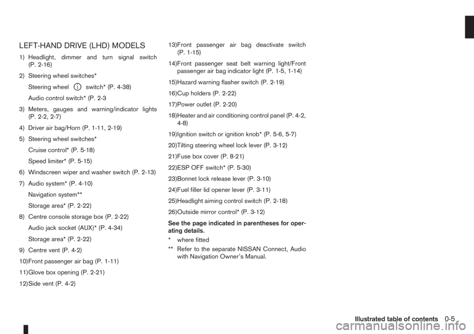
LEFT-HAND DRIVE (LHD) MODELS
1) Headlight, dimmer and turn signal switch
(P. 2-16)
2) Steering wheel switches*
Steering wheel
switch* (P. 4-38)
Audio control switch* (P. 2-3
3) Meters, gauges and warning/indicator lights
(P. 2-2, 2-7)
4) Driver air bag/Horn (P. 1-11, 2-19)
5) Steering wheel switches*
Cruise control* (P. 5-18)
Speed limiter* (P. 5-15)
6) Windscreen wiper and washer switch (P. 2-13)
7) Audio system* (P. 4-10)
Navigation system**
Storage area* (P. 2-22)
8) Centre console storage box (P. 2-22)
Audio jack socket (AUX)* (P. 4-34)
Storage area* (P. 2-22)
9) Centre vent (P. 4-2)
10)Front passenger air bag (P. 1-11)
11)Glove box opening (P. 2-21)
12)Side vent (P. 4-2)13)Front passenger air bag deactivate switch
(P. 1-15)
14)Front passenger seat belt warning light/Front
passenger air bag indicator light (P. 1-5, 1-14)
15)Hazard warning flasher switch (P. 2-19)
16)Cup holders (P. 2-22)
17)Power outlet (P. 2-20)
18)Heater and air conditioning control panel (P. 4-2,
4-8)
19)Ignition switch or ignition knob* (P. 5-6, 5-7)
20)Tilting steering wheel lock lever (P. 3-12)
21)Fuse box cover (P. 8-21)
22)ESP OFF switch* (P. 5-30)
23)Bonnet lock release lever (P. 3-10)
24)Fuel filler lid opener lever (P. 3-11)
25)Headlight aiming control switch (P. 2-18)
26)Outside mirror control* (P. 3-12)
See the page indicated in parentheses for oper-
ating details.
* where fitted
** Refer to the separate NISSAN Connect, Audio
with Navigation Owner’s Manual.
Illustrated table of contents0-5
Page 13 of 235
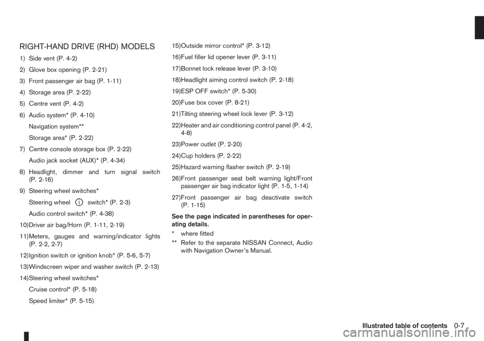
RIGHT-HAND DRIVE (RHD) MODELS
1) Side vent (P. 4-2)
2) Glove box opening (P. 2-21)
3) Front passenger air bag (P. 1-11)
4) Storage area (P. 2-22)
5) Centre vent (P. 4-2)
6) Audio system* (P. 4-10)
Navigation system**
Storage area* (P. 2-22)
7) Centre console storage box (P. 2-22)
Audio jack socket (AUX)* (P. 4-34)
8) Headlight, dimmer and turn signal switch
(P. 2-16)
9) Steering wheel switches*
Steering wheel
switch* (P. 2-3)
Audio control switch* (P. 4-38)
10)Driver air bag/Horn (P. 1-11, 2-19)
11)Meters, gauges and warning/indicator lights
(P. 2-2, 2-7)
12)Ignition switch or ignition knob* (P. 5-6, 5-7)
13)Windscreen wiper and washer switch (P. 2-13)
14)Steering wheel switches*
Cruise control* (P. 5-18)
Speed limiter* (P. 5-15)15)Outside mirror control* (P. 3-12)
16)Fuel filler lid opener lever (P. 3-11)
17)Bonnet lock release lever (P. 3-10)
18)Headlight aiming control switch (P. 2-18)
19)ESP OFF switch* (P. 5-30)
20)Fuse box cover (P. 8-21)
21)Tilting steering wheel lock lever (P. 3-12)
22)Heater and air conditioning control panel (P. 4-2,
4-8)
23)Power outlet (P. 2-20)
24)Cup holders (P. 2-22)
25)Hazard warning flasher switch (P. 2-19)
26)Front passenger seat belt warning light/Front
passenger air bag indicator light (P. 1-5, 1-14)
27)Front passenger air bag deactivate switch
(P. 1-15)
See the page indicated in parentheses for oper-
ating details.
* where fitted
** Refer to the separate NISSAN Connect, Audio
with Navigation Owner’s Manual.
Illustrated table of contents0-7
Page 14 of 235
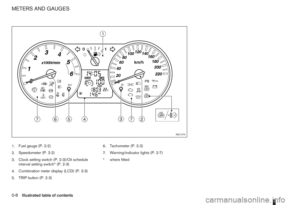
1.Fuel gauge (P. 2-2)
2.Speedometer (P. 2-2)
3.Clock setting switch (P. 2-3)/Oil schedule
interval setting switch* (P. 2-3)
4.Combination meter display (LCD) (P. 2-3)
5.TRIP button (P. 2-3)6.Tachometer (P. 2-2)
7.Warning/indicator lights (P. 2-7)
*where fitted
NIC1474
METERS AND GAUGES
0-8Illustrated table of contents
Page 17 of 235
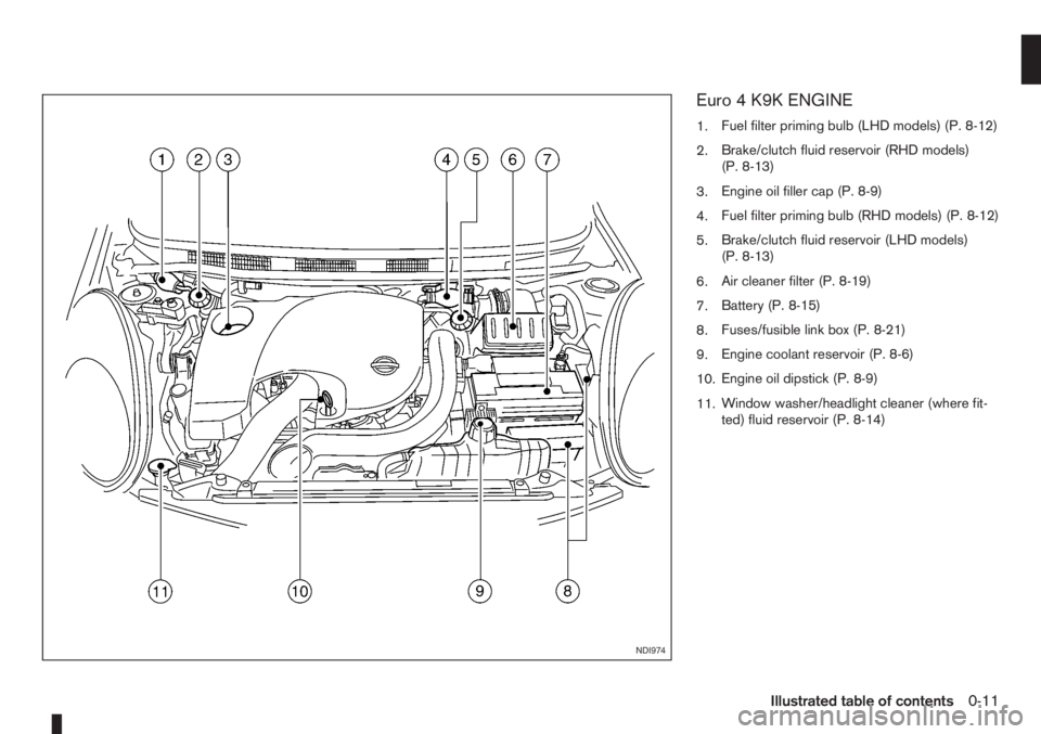
Euro 4 K9K ENGINE
1.Fuel filter priming bulb (LHD models) (P. 8-12)
2.Brake/clutch fluid reservoir (RHD models)
(P. 8-13)
3.Engine oil filler cap (P. 8-9)
4.Fuel filter priming bulb (RHD models) (P. 8-12)
5.Brake/clutch fluid reservoir (LHD models)
(P. 8-13)
6.Air cleaner filter (P. 8-19)
7.Battery (P. 8-15)
8.Fuses/fusible link box (P. 8-21)
9.Engine coolant reservoir (P. 8-6)
10.Engine oil dipstick (P. 8-9)
11.Window washer/headlight cleaner (where fit-
ted) fluid reservoir (P. 8-14)
NDI974
Illustrated table of contents0-11
Page 18 of 235
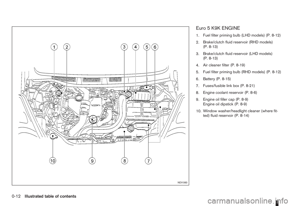
Euro 5 K9K ENGINE
1.Fuel filter priming bulb (LHD models) (P. 8-12)
2.Brake/clutch fluid reservoir (RHD models)
(P. 8-13)
3.Brake/clutch fluid reservoir (LHD models)
(P. 8-13)
4.Air cleaner filter (P. 8-19)
5.Fuel filter priming bulb (RHD models) (P. 8-12)
6.Battery (P. 8-15)
7.Fuses/fusible link box (P. 8-21)
8.Engine coolant reservoir (P. 8-6)
9.Engine oil filler cap (P. 8-9)
Engine oil dipstick (P. 8-9)
10.Window washer/headlight cleaner (where fit-
ted) fluid reservoir (P. 8-14)
NDI1060
0-12Illustrated table of contents
Page 43 of 235
2Instruments and controlsInstruments and controls
Meters and gauges .................................................. 2-2
Speedometer...................................................... 2-2
Tachometer ........................................................ 2-2
Fuel gauge ......................................................... 2-2
Combination meter display (LCD) ....................... 2-3
Odometer/twin trip odometer .............................. 2-3
Trip computer (where fitted)................................ 2-3
Outside temperature display ............................... 2-4
Engine oil level information (where fitted)............. 2-4
Digital clock ........................................................ 2-5
Warning/indicator lights and audible reminders ........ 2-7
Checking bulbs .................................................. 2-7
Warning lights .................................................... 2-7
Indicator lights .................................................... 2-11
Audible reminders............................................... 2-12
Wiper and washer switch ........................................ 2-13
Windscreen wiper and washer switch ................. 2-13
Rear window ...................................................... 2-14
Defogger switch ...................................................... 2-15
Rear window defogger ....................................... 2-15
Outside mirror defogger (where fitted) ................ 2-15
Headlight and turn signal switch............................... 2-16
Headlight switch ................................................. 2-16
Turn signal switch ............................................... 2-17
Fog light switch ....................................................... 2-17
Front fog light (where fitted) ................................ 2-17Rear fog light switch ........................................... 2-18
Headlight aiming control .......................................... 2-18
Headlight aiming control switch........................... 2-18
Hazard warning flasher switch ................................. 2-19
Horn ........................................................................ 2-19
Seat heating (where fitted) ....................................... 2-19
Power outlet ............................................................ 2-20
Storage ................................................................... 2-21
Glove box ........................................................... 2-21
Centre console storage box ................................ 2-22
Cup holder ......................................................... 2-22
Rear foldable tables (where fitted)....................... 2-23
Seat pockets (where fitted) ................................. 2-23
Convenience hook (where fitted)......................... 2-23
Under seat storage tray (where fitted) ................. 2-23
“Flexi-board” System (where fitted) ..................... 2-24
Utility hooks (where fitted)................................... 2-25
Power windows ....................................................... 2-25
Driver’s side main switch .................................... 2-26
Passenger’s side switch ..................................... 2-26
Automatic operation ............................................ 2-26
Interior lights ............................................................ 2-27
Room light .......................................................... 2-27
Map light (where fitted) ....................................... 2-28
Luggage compartment light ................................ 2-28
Page 44 of 235
For an overview of the instruments of the instru-
ments and controls, see “Instrument and control
layout” in the “0. Illustrated table of contents” sec-
tion.
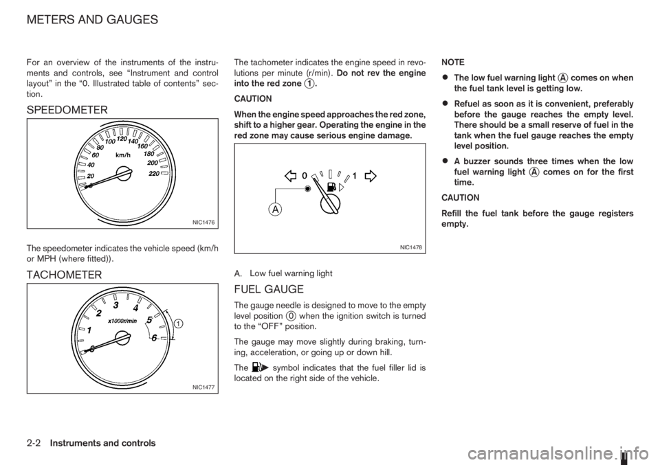
SPEEDOMETER
The speedometer indicates the vehicle speed (km/h
or MPH (where fitted)).
TACHOMETER
The tachometer indicates the engine speed in revo-
lutions per minute (r/min).Do not rev the engine
into the red zone
j1.
CAUTION
When the engine speed approaches the red zone,
shift to a higher gear. Operating the engine in the
red zone may cause serious engine damage.
A.Low fuel warning light
FUEL GAUGE
The gauge needle is designed to move to the empty
level positionj0 when the ignition switch is turned
to the “OFF” position.
The gauge may move slightly during braking, turn-
ing, acceleration, or going up or down hill.
The
csymbol indicates that the fuel filler lid is
located on the right side of the vehicle.NOTE
•The low fuel warning lightjA comes on when
the fuel tank level is getting low.
•Refuel as soon as it is convenient, preferably
before the gauge reaches the empty level.
There should be a small reserve of fuel in the
tank when the fuel gauge reaches the empty
level position.
•A buzzer sounds three times when the low
fuel warning lightjA comes on for the first
time.
CAUTION
Refill the fuel tank before the gauge registers
empty.
NIC1476
NIC1477
NIC1478
METERS AND GAUGES
2-2Instruments and controls
Page 45 of 235
COMBINATION METER DISPLAY
(LCD)
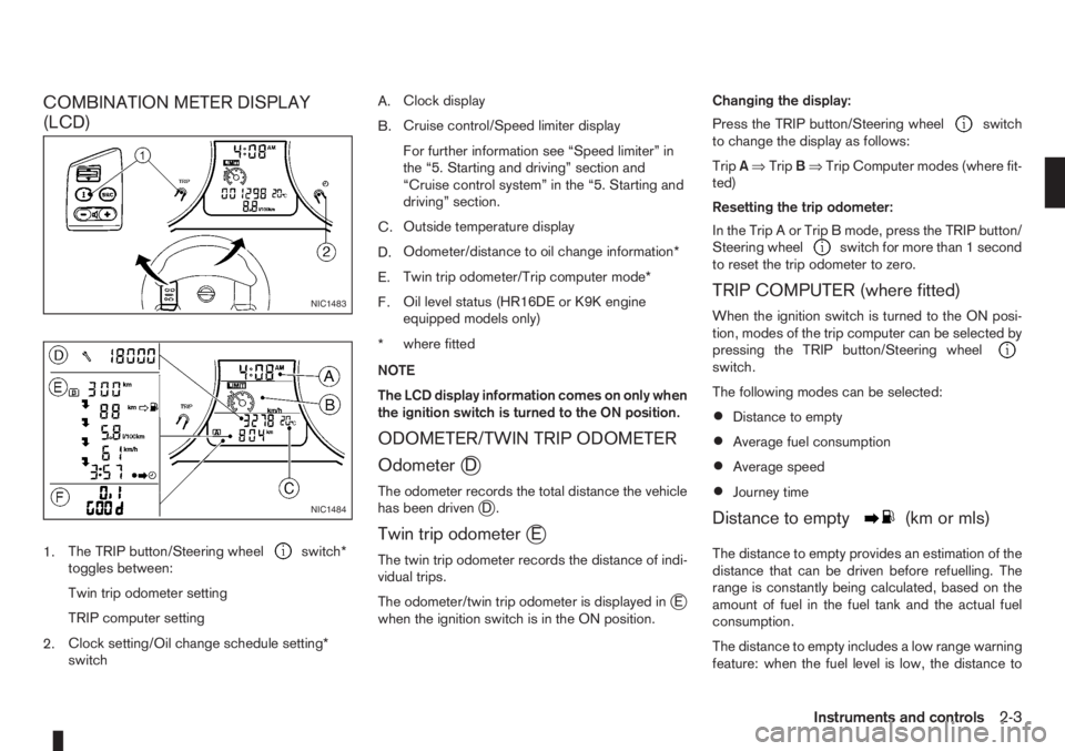
1.The TRIP button/Steering wheelswitch*
toggles between:
Twin trip odometer setting
TRIP computer setting
2.Clock setting/Oil change schedule setting*
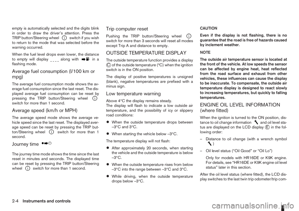
switchA.Clock display
B.Cruise control/Speed limiter display
For further information see “Speed limiter” in
the “5. Starting and driving” section and
“Cruise control system” in the “5. Starting and
driving” section.
C.Outside temperature display
D.Odometer/distance to oil change information*
E.Twin trip odometer/Trip computer mode*
F.Oil level status (HR16DE or K9K engine
equipped models only)
*where fitted
NOTE
The LCD display information comes on only when
the ignition switch is turned to the ON position.
ODOMETER/TWIN TRIP ODOMETER
Odometer
jD
The odometer records the total distance the vehicle
has been drivenjD.
Twin trip odometerjE
The twin trip odometer records the distance of indi-
vidual trips.
The odometer/twin trip odometer is displayed in
jE
when the ignition switch is in the ON position.Changing the display:
Press the TRIP button/Steering wheel
switch
to change the display as follows:
TripA⇒TripB⇒Trip Computer modes (where fit-
ted)
Resetting the trip odometer:
In the Trip A or Trip B mode, press the TRIP button/
Steering wheel
switch for more than 1 second
to reset the trip odometer to zero.
TRIP COMPUTER (where fitted)
When the ignition switch is turned to the ON posi-
tion, modes of the trip computer can be selected by
pressing the TRIP button/Steering wheel
switch.
The following modes can be selected:
•Distance to empty
•Average fuel consumption
•Average speed
•Journey time
Distance to emptym(km or mls)
The distance to empty provides an estimation of the
distance that can be driven before refuelling. The
range is constantly being calculated, based on the
amount of fuel in the fuel tank and the actual fuel
consumption.
The distance to empty includes a low range warning
feature: when the fuel level is low, the distance to
NIC1483
NIC1484
Instruments and controls2-3
Page 46 of 235
empty is automatically selected and the digits blink
in order to draw the driver’s attention. Press the
TRIP button/Steering wheel
switch if you wish
to return to the mode that was selected before the
warning occurred.
When the fuel level drops even lower, the distance
to empty will display
along within a
flashing mode.
Average fuel consumption (l/100 km or
mpg)
The average fuel consumption mode shows the av-
erage fuel consumption since the last reset. The dis-
played average fuel consumption can be reset by
pressing the TRIP button/Steering wheel
switch for more than 1 second.
Average speed (km/h or MPH)
The average speed mode shows the average ve-
hicle speed since the last reset. The displayed aver-
age speed can be reset by pressing the TRIP but-
ton/Steering wheel
switch for more than 1
second.
Journey timem
The journey time mode shows the time since the last
reset in minutes and seconds. The displayed time
can be reset by pressing the TRIP button/Steering
wheel
switch for more than 1 second.
Trip computer reset
Pushing the TRIP button/Steering wheelswitch for more than 3 seconds will reset all modes
except Trip A and distance to empty.
OUTSIDE TEMPERATURE DISPLAY
The outside temperature function provides a displayjC of the outside temperature (ºC) when the ignition
switch is in the ON position.
The display of positive temperatures is unsigned
(blank), negative temperatures are prefixed with a
minus sign.
Low temperature warning
Above 4°C the display remains steady.
The display will flash to indicate a low outside air
temperature, and the possibility of icy or slippery
road conditions:
•When the outside temperature drops between
–3°C and 3°C.
•When starting the vehicle below –3°C.
The temperature display will not flash:
•After approximately 20 seconds, when starting
the vehicle and the outside temperature is below
–3°C.
•When the outside temperature rises from below
–3°C into the range between –3°C and 3°C.
•While driving, when the outside temperature
drops below –3°C.CAUTION
Even if the display is not flashing, there is no
guarantee that the road is free of hazards caused
by inclement weather.
NOTE
The outside air temperature sensor is located at
the front of the vehicle. At low speeds the sensor
can be affected by engine heat, heat reflected
from the road surface and exhaust from other
vehicles, these influences can cause the display
to be inaccurate. To compensate, the outside air
temperature display is designed to react slowly
to increasing temperatures, but quickly to falling
temperatures.
ENGINE OIL LEVEL INFORMATION
(where fitted)
When the ignition is turned to the ON position, dis-
tance to oil change informationand oil level sta-
tus are displayed on the LCD displayjE in the fol-
lowing order:
– Distance to oil change (with a wrench symbol
)
– Oil level status (“Oil Good” or “Oil Lo”)
Only for models with HR16DE or K9K engine.
For details, see “HR16DE or K9K engine oil level
status” later in this section.
After the oil level status (where fitted), the LCD dis-
play switches to the last twin trip odometer/trip com-
2-4Instruments and controls