NISSAN NOTE 2008 Manual Online
Manufacturer: NISSAN, Model Year: 2008, Model line: NOTE, Model: NISSAN NOTE 2008Pages: 235, PDF Size: 2.29 MB
Page 81 of 235
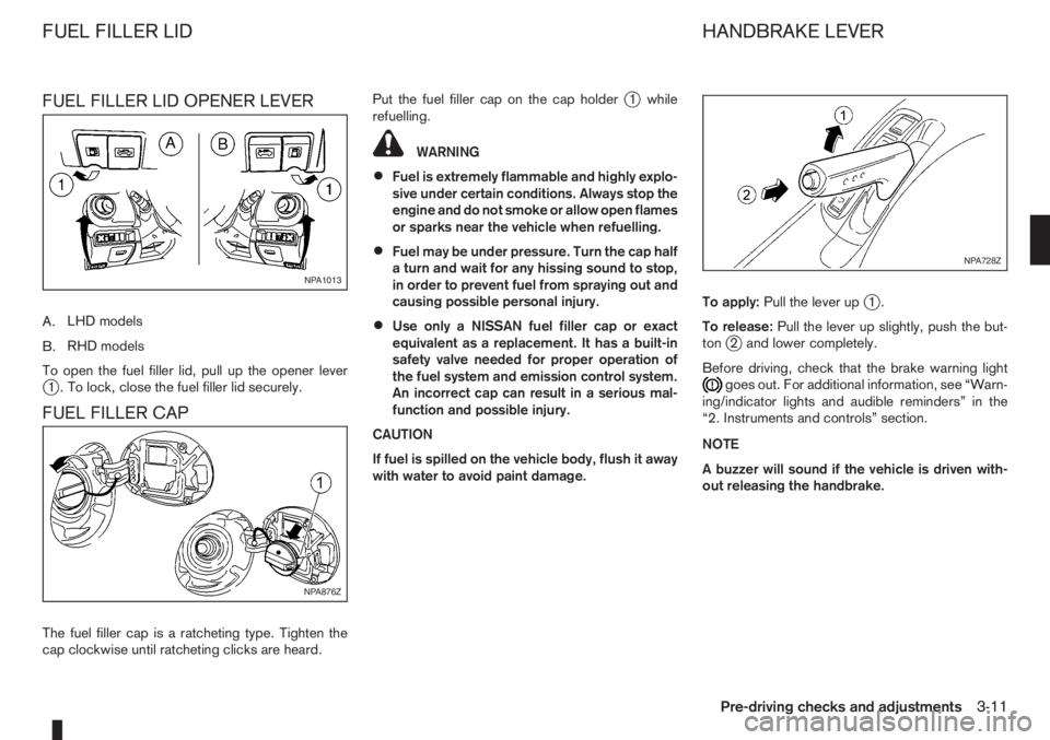
FUEL FILLER LID OPENER LEVER
A.LHD models
B.RHD models
To open the fuel filler lid, pull up the opener lever
j1 . To lock, close the fuel filler lid securely.
FUEL FILLER CAP
The fuel filler cap is a ratcheting type. Tighten the
cap clockwise until ratcheting clicks are heard.Put the fuel filler cap on the cap holder
j1 while
refuelling.
WARNING
•Fuel is extremely flammable and highly explo-
sive under certain conditions. Always stop the
engine and do not smoke or allow open flames
or sparks near the vehicle when refuelling.
•Fuel may be under pressure. Turn the cap half
a turn and wait for any hissing sound to stop,
in order to prevent fuel from spraying out and
causing possible personal injury.
•Use only a NISSAN fuel filler cap or exact
equivalent as a replacement. It has a built-in
safety valve needed for proper operation of
the fuel system and emission control system.
An incorrect cap can result in a serious mal-
function and possible injury.
CAUTION
If fuel is spilled on the vehicle body, flush it away
with water to avoid paint damage.To apply:Pull the lever up
j1.
To release:Pull the lever up slightly, push the but-
ton
j2 and lower completely.
Before driving, check that the brake warning light
goes out. For additional information, see “Warn-
ing/indicator lights and audible reminders” in the
“2. Instruments and controls” section.
NOTE
A buzzer will sound if the vehicle is driven with-
out releasing the handbrake.
NPA1013
NPA876Z
NPA728Z
FUEL FILLER LID HANDBRAKE LEVER
Pre-driving checks and adjustments3-11
Page 82 of 235
WARNING
Do not adjust the steering wheel while driving.
You could lose control of your vehicle and cause
an accident.
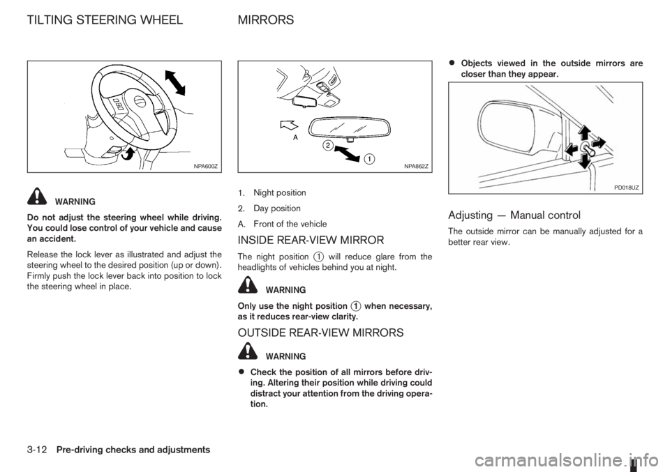
Release the lock lever as illustrated and adjust the
steering wheel to the desired position (up or down).
Firmly push the lock lever back into position to lock
the steering wheel in place.1.Night position
2.Day position
A.Front of the vehicle
INSIDE REAR-VIEW MIRROR
The night positionj1 will reduce glare from the
headlights of vehicles behind you at night.
WARNING
Only use the night position
j1 when necessary,
as it reduces rear-view clarity.
OUTSIDE REAR-VIEW MIRRORS
WARNING
•Check the position of all mirrors before driv-
ing. Altering their position while driving could
distract your attention from the driving opera-
tion.
•Objects viewed in the outside mirrors are
closer than they appear.
Adjusting — Manual control
The outside mirror can be manually adjusted for a
better rear view.
NPA600ZNPA862Z
PD018UZ
TILTING STEERING WHEEL MIRRORS
3-12Pre-driving checks and adjustments
Page 83 of 235
Adjusting — Remote control
(where fitted)
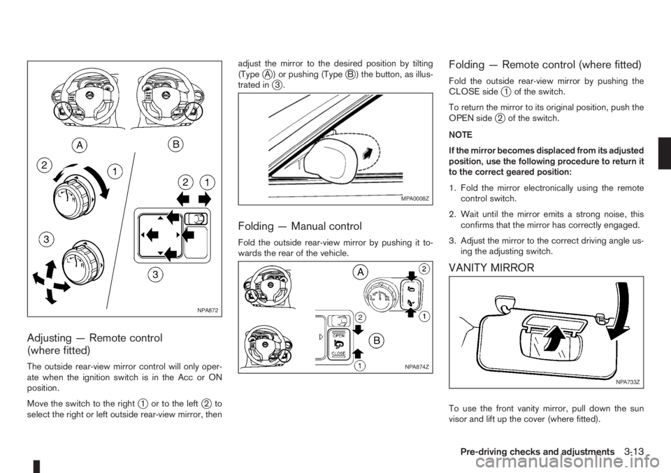
The outside rear-view mirror control will only oper-
ate when the ignition switch is in the Acc or ON
position.
Move the switch to the right
j1 or to the leftj2to
select the right or left outside rear-view mirror, thenadjust the mirror to the desired position by tilting
(Type
jA ) or pushing (TypejB ) the button, as illus-
trated inj3.
Folding — Manual control
Fold the outside rear-view mirror by pushing it to-
wards the rear of the vehicle.
Folding — Remote control (where fitted)
Fold the outside rear-view mirror by pushing the
CLOSE sidej1 of the switch.
To return the mirror to its original position, push the
OPEN side
j2 of the switch.
NOTE
If the mirror becomes displaced from its adjusted
position, use the following procedure to return it
to the correct geared position:
1. Fold the mirror electronically using the remote
control switch.
2. Wait until the mirror emits a strong noise, this
confirms that the mirror has correctly engaged.
3. Adjust the mirror to the correct driving angle us-
ing the adjusting switch.
VANITY MIRROR
To use the front vanity mirror, pull down the sun
visor and lift up the cover (where fitted).
NPA872
MPA0008Z
NPA874Z
NPA733Z
Pre-driving checks and adjustments3-13
Page 84 of 235
WARNING
Never put anything on the rear parcel shelf, no
matter how small. Any object on it could cause
an injury in an accident or when the brakes are
applied suddenly.
CAUTION
The rear parcel shelf flap provides a hide-awayfacility to the luggage compartment whether the
rear seat is at its rearmost position or not. Do not
store objects onto the rear parcel shelf flap as it
may impair the sliding operation of the rear seat.
REAR PARCEL SHELF REMOVAL
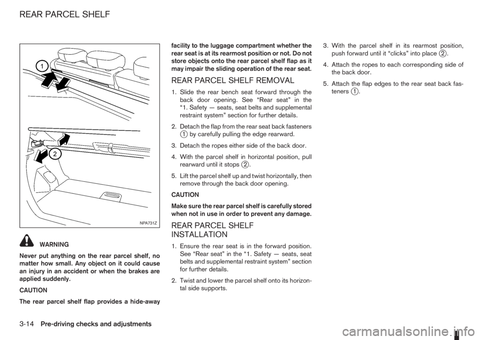
1. Slide the rear bench seat forward through the
back door opening. See “Rear seat” in the
“1. Safety — seats, seat belts and supplemental
restraint system” section for further details.
2. Detach the flap from the rear seat back fasteners
j1 by carefully pulling the edge rearward.
3. Detach the ropes either side of the back door.
4. With the parcel shelf in horizontal position, pull
rearward until it stops
j2.
5. Lift the parcel shelf up and twist horizontally, then
remove through the back door opening.
CAUTION
Make sure the rear parcel shelf is carefully stored
when not in use in order to prevent any damage.
REAR PARCEL SHELF
INSTALLATION
1. Ensure the rear seat is in the forward position.
See “Rear seat” in the “1. Safety — seats, seat
belts and supplemental restraint system” section
for further details.
2. Twist and lower the parcel shelf onto its horizon-
tal side supports.3. With the parcel shelf in its rearmost position,
push forward until it “clicks” into place
j2.
4. Attach the ropes to each corresponding side of
the back door.
5. Attach the flap edges to the rear seat back fas-
teners
j1.
NPA731Z
REAR PARCEL SHELF
3-14Pre-driving checks and adjustments
Page 85 of 235
4Heater and air conditioner, and audio systemHeater and air conditioner, and audio system
Vents ....................................................................... 4-2
Side vents .......................................................... 4-2
Centre vents ....................................................... 4-2
Heater and air conditioner operation ........................ 4-2
Manual air conditioner......................................... 4-3
Automatic air conditioner (where fitted) ............... 4-8
Audio system ........................................................... 4-10
Audio operation precautions ............................... 4-10
Antenna .............................................................. 4-16
LW-MW-FM radio with CD player (where fitted) ...... 4-16
Anti-theft system ................................................. 4-16
Audio main operation .......................................... 4-17
Radio operation .................................................. 4-19
User set up menu ............................................... 4-21
Compact disc (CD) player operation ................... 4-22
FM AM radio with CD player (where fitted) .............. 4-23
Anti-theft system ................................................. 4-23
Audio main operation .......................................... 4-24
Radio operation .................................................. 4-25SETUP button .................................................... 4-26
Compact Disc (CD) operation ............................ 4-27
AUX socket ........................................................ 4-29
USB Memory operation ...................................... 4-29
iPod® player operation ....................................... 4-30
Bluetooth® operation.......................................... 4-31
Bluetooth® mobile phone feature ........................ 4-33
AM-FM radio with CD player and navigation
(where fitted) ........................................................... 4-34
Audio jack socket (AUX) (where fitted) ..................... 4-34
Mobile phone integration (where fitted) .................... 4-34
Bluetooth® mobile phone feature ........................ 4-34
Hands-free telephone control .............................. 4-36
Steering wheel switches (where fitted) ................ 4-38
Steering wheel switches for audio control (where
fitted) ....................................................................... 4-38
Main operation .................................................... 4-38
Car phone or CB radio ............................................ 4-39
Page 86 of 235
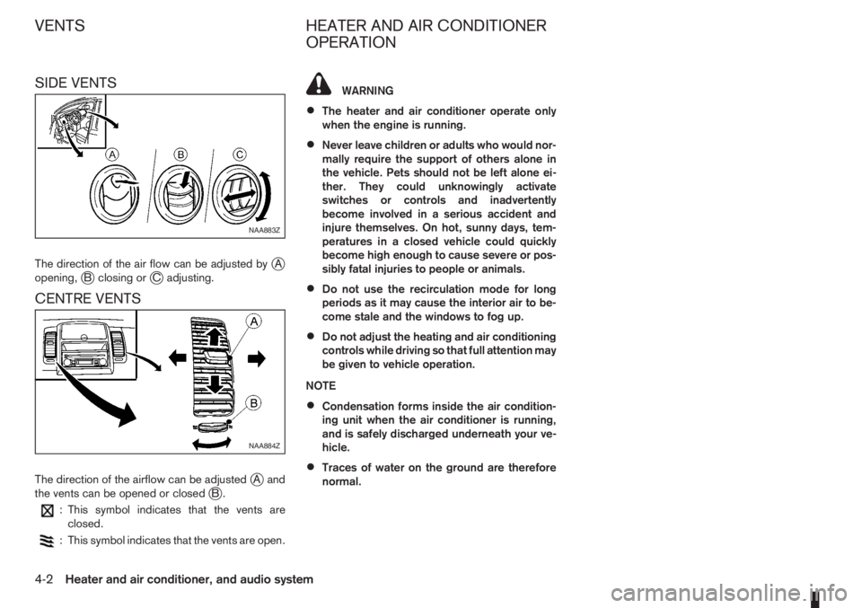
SIDE VENTS
The direction of the air flow can be adjusted byjA
opening,jB closing orjC adjusting.
CENTRE VENTS
The direction of the airflow can be adjustedjAand
the vents can be opened or closedjB.
: This symbol indicates that the vents are
closed.
: This symbol indicates that the vents are open.
WARNING
•The heater and air conditioner operate only
when the engine is running.
•Never leave children or adults who would nor-
mally require the support of others alone in
the vehicle. Pets should not be left alone ei-
ther. They could unknowingly activate
switches or controls and inadvertently
become involved in a serious accident and
injure themselves. On hot, sunny days, tem-
peratures in a closed vehicle could quickly
become high enough to cause severe or pos-
sibly fatal injuries to people or animals.
•Do not use the recirculation mode for long
periods as it may cause the interior air to be-
come stale and the windows to fog up.
•Do not adjust the heating and air conditioning
controls while driving so that full attention may
be given to vehicle operation.
NOTE
•Condensation forms inside the air condition-
ing unit when the air conditioner is running,
and is safely discharged underneath your ve-
hicle.
•Traces of water on the ground are therefore
normal.
NAA883Z
NAA884Z
VENTS HEATER AND AIR CONDITIONER
OPERATION
4-2Heater and air conditioner, and audio system
Page 87 of 235
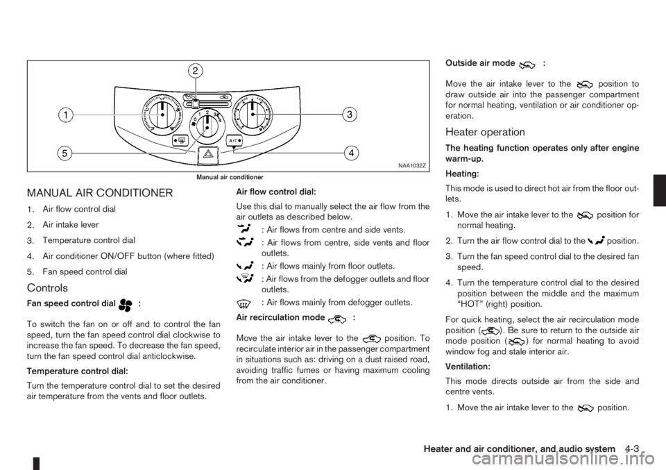
MANUAL AIR CONDITIONER
1.Air flow control dial
2.Air intake lever
3.Temperature control dial
4.Air conditioner ON/OFF button (where fitted)
5.Fan speed control dial
Controls
Fan speed control dialm:
To switch the fan on or off and to control the fan
speed, turn the fan speed control dial clockwise to
increase the fan speed. To decrease the fan speed,
turn the fan speed control dial anticlockwise.
Temperature control dial:
Turn the temperature control dial to set the desired
air temperature from the vents and floor outlets.Air flow control dial:
Use this dial to manually select the air flow from the
air outlets as described below.
: Air flows from centre and side vents.
: Air flows from centre, side vents and floor
outlets.
: Air flows mainly from floor outlets.
: Air flows from the defogger outlets and floor
outlets.
: Air flows mainly from defogger outlets.
Air recirculation mode
m:
Move the air intake lever to the
position. To
recirculate interior air in the passenger compartment
in situations such as: driving on a dust raised road,
avoiding traffic fumes or having maximum cooling
from the air conditioner.Outside air mode
m:
Move the air intake lever to the
position to
draw outside air into the passenger compartment
for normal heating, ventilation or air conditioner op-
eration.
Heater operation
The heating function operates only after engine
warm-up.
Heating:
This mode is used to direct hot air from the floor out-
lets.
1. Move the air intake lever to the
position for
normal heating.
2. Turn the air flow control dial to the
position.
3. Turn the fan speed control dial to the desired fan
speed.
4. Turn the temperature control dial to the desired
position between the middle and the maximum
“HOT” (right) position.
For quick heating, select the air recirculation mode
position (
). Be sure to return to the outside air
mode position () for normal heating to avoid
window fog and stale interior air.
Ventilation:
This mode directs outside air from the side and
centre vents.
1. Move the air intake lever to the
position.
NAA1032Z
Manual air conditioner
Heater and air conditioner, and audio system4-3
Page 88 of 235
2. Turn the air flow control dial to theposition.
3. Turn the fan speed control dial to the desired fan
speed.
4. Turn the temperature control dial to the desired
position.
Defrosting or defogging:
This mode is used to defrost/defog the windows.
1. Move the air intake lever to the
position.
2. Turn the air flow control dial to the
position.
3. Turn the fan speed control dial to speed position
2 or above.
4. Turn the temperature control dial to the desired
position between the middle and the maximum
“HOT” (right) position.
To quickly defrost/defog the windscreen, turn the
fan speed control dial to the maximum position and
the temperature control dial to the maximum “HOT”
(right) position.
Heating and defogging:
This mode heats the interior and defogs the wind-
screen.
1. Move the air intake lever to outside air mode
position (
).
2. Turn the air flow control dial to the
position.
3. Turn the fan speed control dial to speed position
2 or above.4. Turn the temperature control dial between the
middle and the maximum “HOT” (right) position.
Air conditioner operation (where fitted)
Start the engine, turn the fan speed control dial to
the desired fan speed and press the A/C button to
activate the air conditioner. When the air conditioner
is on, cooling and dehumidifying functions will be
added to the heater operation. To switch off the air
conditioner, press the button again.
NOTE
The air conditioner cooling function operates only
when the engine is running.
Cooling:
This mode is used to cool and dehumidify.
1. Move the air intake lever to outside air mode
position (
).
2. Turn the air flow control dial to the
position.
3. Turn the fan speed control dial to the desired fan
speed.
4. Press thebutton and the indicator light
will come on.
5. Turn the temperature control dial to the desired
position.
For quick cooling when the outside temperature is
high, select the air recirculation mode position
(
). Be sure to return to the outside air mode
position () to avoid windows from fogging-up
and interior air from becoming stale.NOTE
A visible mist may be seen coming from the vents
in hot, humid conditions as the air is cooled rap-
idly. This does not indicate a malfunction.
Dehumidified heating:
This mode is used to heat and dehumidify.
1. Move the air intake lever to outside air mode
position (
).
2. Turn the air flow control dial to the
position.
3. Turn on the fan speed control dial to the desired
fan speed.
4. Press thebutton and the indicator light
will come on.
5. Turn the temperature control dial to the desired
position.
Dehumidified defogging:
This mode is used to defog the windows and dehu-
midify.
1. Move the air intake lever to outside air mode
position (
).
2. Turn the air flow control dial to the
position.
3. Turn the fan speed control dial to the desired fan
speed.
4. Press thebutton and the indicator light
will come on.
5. Turn the temperature control dial to the desired
position.
4-4Heater and air conditioner, and audio system
Page 89 of 235
Operating tips
•In order to improve the heater operation, clear
the snow and ice from the wiper blade and air
inlet in front of the windscreen.
•After parking in the sun, drive for two or three
minutes with the windows open to vent hot air
from the passenger compartment. Then close
the windows to allow the acceleration of the air
conditioner’s cooling operation.
•Keep the windows closed while the air condi-
tioner is operating.
•The air conditioning system should be operated
for about 10 minutes, at least once a month. This
helps prevent damage to the system due to lack
of lubrication.
•If the coolant temperature warning light comes
on, turn the air conditioner off. For additional
information, see “Engine overheat” in the “6. In
case of emergency” section.
•If the engine coolant reaches an extremely high
temperature, the air conditioning system will au-
tomatically turn off. This may happen for example
if the engine runs at idle speed for a long time on
a hot day.
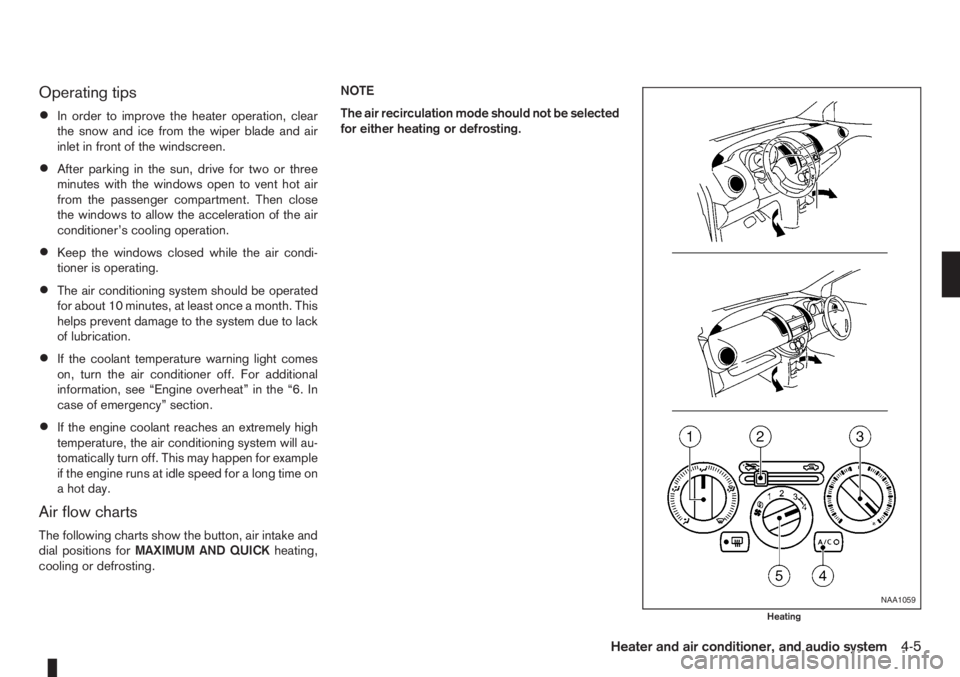
Air flow charts
The following charts show the button, air intake and
dial positions forMAXIMUM AND QUICKheating,
cooling or defrosting.NOTE
The air recirculation mode should not be selected
for either heating or defrosting.
NAA1059
Heating
Heater and air conditioner, and audio system4-5
Page 90 of 235

HEATING
Controls Settings
j1 Air flow control dialm
j2 Air intake leverm
j3 Temperature control dial HOT
j4Air conditioner button
(where fitted)OFF
j5 Fan speed control dial MAX
DEFROSTING/DEFOGGING
Controls Settings
j1 Air flow control dialm
j2 Air intake leverm
j3 Temperature control dial HOT
j4Air conditioner button
(where fitted)ON
j5 Fan speed control dial MAX
NAA1060
Defrosting/Defogging
4-6Heater and air conditioner, and audio system