Rpm NISSAN NOTE 2008 Owners Manual
[x] Cancel search | Manufacturer: NISSAN, Model Year: 2008, Model line: NOTE, Model: NISSAN NOTE 2008Pages: 235, PDF Size: 2.29 MB
Page 128 of 235

NISSAN GREEN PROGRAM
The three-way catalyst is an emission control device
installed in the exhaust system. In the converter,
exhaust gases are burned at high temperatures to
help reduce pollutants.
CAUTION
•The exhaust gas and the exhaust system are
very hot. While the engine is running, keep
people or flammable materials away from the
exhaust pipe.
•Do not stop or park the vehicle over flam-
mable materials such as dry grass, waste pa-
per or rags, as they may burn easily.
•When parking, ensure that people or flam-
mable materials are kept away from the ex-
haust pipe.
TO HELP PREVENT DAMAGE
CAUTION
•Use UNLEADED PETROL ONLY, specifically
the recommended type. For details, see “Ca-
pacities and recommended fuel/lubricants” in
the “9. Technical information” section.
•Do not use leaded petrol. Leaded petrol will
seriously damage three-way catalyst.
Deposits from leaded petrol will seriously re-
duce the three-way catalyst’s ability to help
reduce exhaust pollutants.
•Keep your engine tuned up. Malfunctions in
the ignition, fuel injection, or electrical sys-
tems can cause over-rich fuel flow into the
converter, causing it to overheat.
•Avoid driving with an extremely low fuel level.
Running out of fuel could cause the engine to
misfire, damaging the three-way catalyst.
•Do not keep driving if the engine misfires, or
if noticeable loss of performance or other un-
usual operating conditions are detected. Have
the vehicle inspected promptly by a NISSAN
dealer or qualified workshop.
•Do not race the engine while warming it up.
•Do not push or tow your vehicle to start the
engine.The turbocharger system uses engine oil for lubrica-
tion and cooling of its rotating components. The tur-
bocharger turbine turns at extremely high speeds
and it can reach an extremely high temperature. It is
essential to maintain a flow of clean oil through the
turbocharger system. A sudden interruption to the
oil supply may cause a malfunction in the turbo-
charger.
To ensure prolonged life and performance of the
turbocharger, it is essential to comply with the fol-
lowing maintenance procedure:
CAUTION
•Change the engine oil of the turbo-charged
diesel engine as prescribed. See the sepa-
rately provided Warranty Information & Main-
tenance Booklet for additional information.
•Use only the recommended engine oil. See
“Capacities and recommended fuel/
lubricants” in the “9. Technical information”
section.
•If the engine has been operating at high rpm
for an extended period of time, let it idle for a
few minutes prior to shutdown.
•Do not accelerate the engine to high rpm im-
mediately after starting it.
THREE-WAY CATALYST (Petrol
engine models)TURBOCHARGER SYSTEM
(Diesel engine models)
5-4Starting and driving
Page 166 of 235

•Never lean over the battery while jump-start-
ing.
•Never allow battery fluid to come into contact
with eyes, skin, clothes or the vehicle’s
painted surfaces. Battery fluid is a corrosive
sulphuric acid which can cause severe burns.
If the fluid comes into contact with anything,
immediately flush the contacted area with
plenty of water.
•Keep the battery out of the reach of children.
•The booster battery must be rated at 12 volts.
Use of an incorrectly rated battery will dam-
age your vehicle.
•Never attempt to jump-start a frozen battery.
It could explode and cause serious injury.
1. Prepare vehicle
jA with the booster battery for
the vehiclejB being jump-started.
CAUTION
Do not allow the two vehicles to touch.
2. Apply the handbrake.
3. Shift the gear lever (MT models) into the N (Neu-
tral) position [AT models, move the selector lever
to the P (Park) position].
4. Switch off all unnecessary electrical systems
(headlights, hazard lights etc,).
5. Ensure that the ignition switch of the vehicle be-
ing jump-started is in the LOCK position.6. Open the bonnet. For details, see “Bonnet
release” in the “3. Pre-driving checks and
adjustments” section.
7. Remove the vent caps (where fitted) on the bat-
tery and cover the battery with an old cloth.
8. Connect the jump leads in the sequence (
j1→j2→j3→j4 ) as illustrated.
CAUTION
•Always connect positivej+ to positivej+
and negativej- to body ground (for ex-
ample, engine lift bracket, etc.) – not to
the battery’s negative
j-.
•An incorrect connection could damage the
charging system.
•Be sure that the jumper cables do not
touch moving parts in the engine compart-
ment.
•Be careful not to allow contact between
the positive jump lead connector and the
vehicle or the negative lead during con-
nection and disconnection.
9. Start the engine of the other vehicle
jA and let it
run for a few minutes. Keep the engine speed at
about 2,000 rpm.
10. Start the engine of your vehicle
jB in the nor-
mal way.
CAUTION
Do not keep the starter motor engaged formore than 10 seconds. If the engine does not
start immediately, turn the ignition switch to
“OFF” and wait 10 seconds before trying
again.
11. After starting the engine of your vehicle, care-
fully disconnect the negative lead and then the
positive lead (
j4→j3→j2→j1).
12. Remove and dispose of the cloth that was used
to cover the vent holes as it may be contami-
nated with corrosive acid.
13. Install the vent caps (where fitted).
14. Close the bonnet.
6-10In case of emergency
Page 183 of 235

WARNING
•To avoid the danger of being scalded, never
change the coolant when the engine is hot.
•Avoid direct skin contact with used coolant. If
skin contact is made, wash thoroughly with
soap or hand cleaner and plenty of water as
soon as possible.
•Keep coolant out of reach of children and
pets.
NISSAN GREEN PROGRAM
Engine coolant must be disposed of properly.
Check your local regulations.
CR14DE or HR16DE engine
1. Set the heater or air conditioner temperature
control to the maximum “HOT” position.
2. Open the bonnet. For details, see “Bonnet
release” in the “3. Pre-driving checks and
adjustments” section.
3. Open the radiator cap
j1 (where fitted) or en-
gine coolant reservoir cap to help to drain the
coolant.
4. Slacken off the radiator lower hose clip
j2and
remove the lower hosej3 to drain the coolant.
5. Flush the cooling system by running clean water
through the radiator filler opening (where fitted)
or engine coolant reservoir.
6. Install the radiator lower hose on the radiator
securely.7. Fill the radiator through the filler opening (where
applicable) slowly with coolant and fill the cool-
ant reservoir up to the MAX level. See “Capaci-
ties and recommended fuel/lubricants” in the
“9. Technical information” section for cooling
system capacity.
8. Install the radiator cap (where fitted) and the en-
gine coolant reservoir cap.
9. Start the engine, and warm it up until the radiator
fan operates. Then rev the engine two or three
times under no load. Observe the coolant tem-
perature warning light for signs of overheating.
10. Stop the engine. After it has completely cooled
down, refill the radiator up to the filler opening
(where fitted). If the coolant level lowered, fill
the engine coolant reservoir up to the MAX level.
11. Check radiator lower hose for any signs of leak-
age.
12. Close the bonnet.
K9K engine
1. Set the heater or air conditioner temperature
control to the maximum “HOT” position.
2. Open the bonnet. For details, see “Bonnet
release” in the “3. Pre-driving checks and
adjustments” section.
3. Disconnect the radiator lower hose
j1 and open
the drain plugj2 on the engine block.
4. Open the engine coolant reservoir cap to help to
drain the coolant.
5. Flush the cooling system by running fresh water
through the radiator.
6. Install the radiator lower hose to the radiator and
securely tighten the engine block drain plug.
7. Fill the reservoir up to the MAX level with cool-
ant. See “Capacities and recommended
fuel/lubricants” in the “9. Technical information”
section for cooling system capacity.
8. Install the engine coolant reservoir cap.
9. Start the engine and run the engine at about
2,000 rpm for 1 minute.
10. Stop the engine and check coolant level, allow
to cool and refill up to the MAX level.
11. Warm up the engine at about 2,000 rpm until it
reaches the normal operational temperature
(fan cycles).
Check heater core (below instrument panel) for
gurgling, refill if necessary.
NDI671Z
K9K engine
Maintenance and do-it-yourself8-7
Page 185 of 235

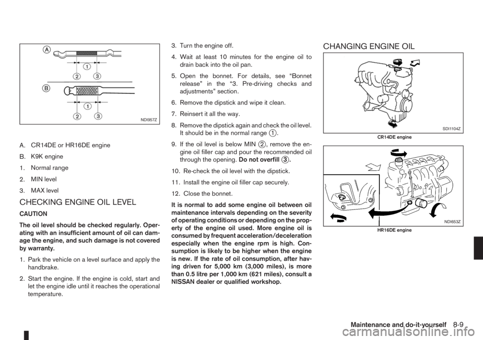
A.CR14DE or HR16DE engine
B.K9K engine
1.Normal range
2.MIN level
3.MAX level
CHECKING ENGINE OIL LEVEL
CAUTION
The oil level should be checked regularly. Oper-
ating with an insufficient amount of oil can dam-
age the engine, and such damage is not covered
by warranty.
1. Park the vehicle on a level surface and apply the
handbrake.
2. Start the engine. If the engine is cold, start and
let the engine idle until it reaches the operational
temperature.3. Turn the engine off.
4. Wait at least 10 minutes for the engine oil to
drain back into the oil pan.
5. Open the bonnet. For details, see “Bonnet
release” in the “3. Pre-driving checks and
adjustments” section.
6. Remove the dipstick and wipe it clean.
7. Reinsert it all the way.
8. Remove the dipstick again and check the oil level.
It should be in the normal range
j1.
9. If the oil level is below MIN
j2 , remove the en-
gine oil filler cap and pour the recommended oil
through the opening.Do not overfill
j3.
10. Re-check the oil level with the dipstick.
11. Install the engine oil filler cap securely.
12. Close the bonnet.
It is normal to add some engine oil between oil
maintenance intervals depending on the severity
of operating conditions or depending on the prop-
erty of the engine oil used. More engine oil is
consumed by frequent acceleration/deceleration
especially when the engine rpm is high. Con-
sumption is likely to be higher when the engine
is new. If the rate of oil consumption, after hav-
ing driven for 5,000 km (3,000 miles), is more
than 0.5 litre per 1,000 km (621 miles), consult a
NISSAN dealer or qualified workshop.
CHANGING ENGINE OIL
NDI957Z
SDI1104Z
CR14DE engine
NDI653Z
HR16DE engine
Maintenance and do-it-yourself8-9
Page 213 of 235

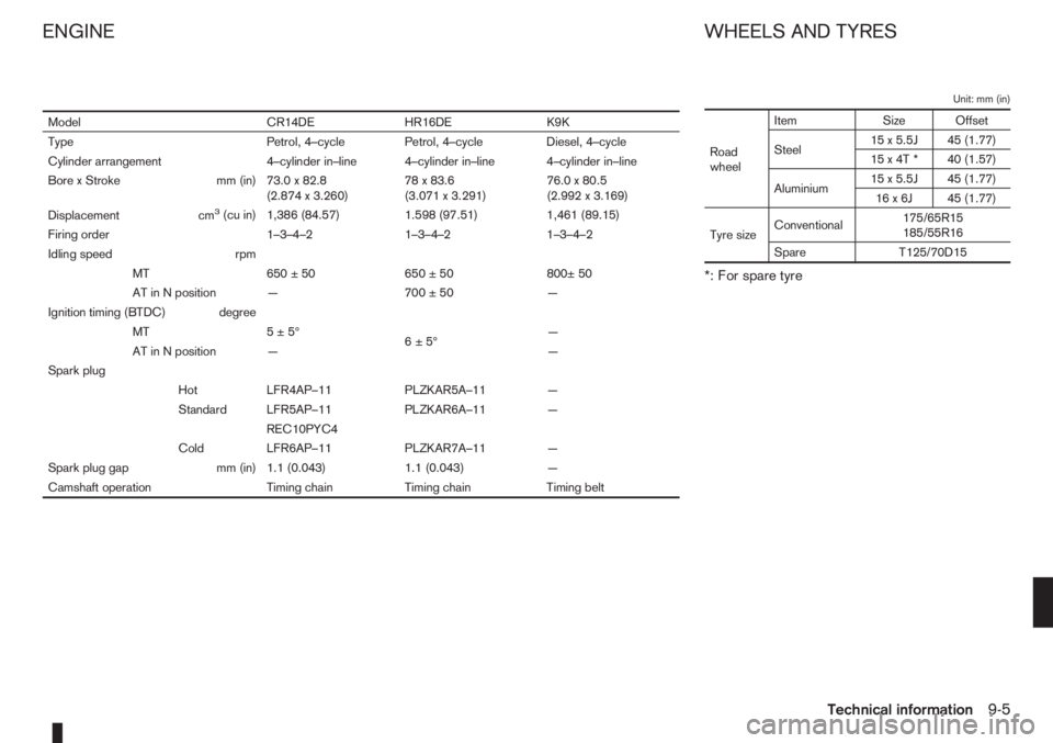
Unit: mm (in)
Road
wheelItem Size Offset
Steel15 x 5.5J 45 (1.77)
15 x 4T * 40 (1.57)
Aluminium15 x 5.5J 45 (1.77)
16 x 6J 45 (1.77)
Tyre sizeConventional175/65R15
185/55R16
Spare T125/70D15
*: For spare tyre
Model CR14DE HR16DE K9K
Type Petrol, 4–cycle Petrol, 4–cycle Diesel, 4–cycle
Cylinder arrangement 4–cylinder in–line 4–cylinder in–line 4–cylinder in–line
Bore x Stroke mm (in) 73.0 x 82.8
(2.874 x 3.260)78 x 83.6
(3.071 x 3.291)76.0 x 80.5
(2.992 x 3.169)
Displacement cm
3(cu in) 1,386 (84.57) 1.598 (97.51) 1,461 (89.15)
Firing order 1–3–4–2 1–3–4–2 1–3–4–2
Idling speed rpm
MT 650 ± 50 650 ± 50 800± 50
AT in N position — 700 ± 50 —
Ignition timing (BTDC) degree
MT 5±5°
6±5°—
AT in N position — —
Spark plug
Hot LFR4AP–11 PLZKAR5A–11 —
Standard LFR5AP–11 PLZKAR6A–11 —
REC10PYC4
Cold LFR6AP–11 PLZKAR7A–11 —
Spark plug gap mm (in) 1.1 (0.043) 1.1 (0.043) —
Camshaft operation Timing chain Timing chain Timing belt
ENGINE WHEELS AND TYRES
Technical information9-5