stop start NISSAN NOTE 2010 Owner's Manual
[x] Cancel search | Manufacturer: NISSAN, Model Year: 2010, Model line: NOTE, Model: NISSAN NOTE 2010Pages: 235, PDF Size: 2.29 MB
Page 142 of 235
sistance point. The speed limiter will be suspended
to allow driving above the set speed. The set speed
value
j9 will flash. The speed limiter will automati-
cally resume when the vehicle speed drops below
the set speed limit.
Resuming previous set speed:
If a set speed limit has been cancelled, the set speed
value
j9 will remain displayed in the combination
meter and the speed will be stored in the speed lim-
iter memory. This speed limit can be reactivated by
pressing the RES (Resume) switch
j1.
If the current vehicle speed is higher than the previ-
ous set speed, the accelerator pedal will not work
and the set speed value
j9 will flash until the vehicle
speed drops below the set speed limit.
Turning the speed limiter off:
The speed limiter system will be turned off when
one of the following operations is performed:
•Push the speed limiter main “ON/OFF” switchj4 . The speed limiter symbolj7 , the LIMIT indi-
catorj6 , the SET indicatorj8 , and the set
speed valuej9 will turn off in the combination
meter display.
•Push the cruise control main “ON/OFF” switchj5 . The speed limiter information in the combi-
nation meter will be replaced with the cruise con-
trol information. For details see “Cruise control
system” later in this section.
•When the vehicle is stopped and the ignition is
turned to the off position.Turning off the speed limiter will erase the set
speed limit memory.
Speed limiter malfunction:
If the speed limiter malfunctions, the set indicator
j8 in the combination meter display will flash. Turn
the speed limiter off by pushing the speed limiter
main “ON/OFF” switch
j4 and have the system
checked by a NISSAN dealer or qualified workshop.The cruise control system allows driving at constant
speeds without keeping your foot on the accelerator
pedal.
WARNING
•The cruise control system ONLY maintains a
constant vehicle speed, it does not replace
the driver.
•Always observe the posted speed limits and
do not set the speed above them.
•Do not use the cruise control system when
driving under the following conditions. Doing
so could cause a loss of vehicle control and
result in an accident.
– When it is not possible to keep the vehicle
at a constant speed
– When driving in heavy traffic
– When driving in traffic that varies speed
– When driving in windy areas
– When driving on winding or hilly roads
– When driving on slippery (rain, snow, ice,
etc.) roads
When the cruise control system is on the speed lim-
iter cannot be operated.
CRUISE CONTROL SYSTEM
5-18Starting and driving
Page 145 of 235
•Push the speed limiter main “ON/OFF” switchj5 . The cruise control system information in the
combination meter will be replaced with the
speed limiter information. For details see “Speed
limiter” earlier in this section.
•When the vehicle is stopped and the ignition is
turned to the off position.
Turning off the cruise control system will erase
the cruise control system memory.
Vehicles with diesel engine
Turning the cruise control system on:
The cruise control system can be switched on after
engine start or when driving.
Push the cruise control main switch
j5 . The
CRUISE indicatorj6 and the cruise control symbolj7 will illuminate in the combination meter display.
Setting a cruising speed:
1. Accelerate to the desired cruising speed.
2. Push the SET switch
j2 upwards or downwards
and release it.
3. The SET indicator
j8 and the set speed valuej9 will be displayed in the combination meter
display.
4. Take your foot off the accelerator pedal.
The vehicle will maintain the set speed.
If the vehicle speed is less than 30 km/h (20
MPH), it will not be possible to set the cruise con-
trol system.Changing a cruising speed:
Use any one of the following methods to change the
cruising speed:
•Slow the vehicle as normal using the footbrake
pedal, the SET indicatorj8 in the combination
meter will be turned off.
When the vehicle reaches the desired cruising
speed, push and release the SET switch
j2 up-
wards or downwards.
The new set speed value
j9 and the SET indica-
torj8 will be displayed in the combination meter.
•Press the accelerator pedal.
When the vehicle reaches the desired cruising
speed, push and release the SET switch
j2 up-
wards or downwards.
The new set speed value
j9 and the SET indica-
torj8 will be displayed in the combination meter.
•Push and release the SET switchj2 upwards or
downwards to increase or decrease the set
speed in steps of 2 km/h (1-2 MPH).
•Push and hold the SET switchj2 upwards or
downwards. The set speed will increase or de-
crease in steps of 4 km/h (2-3 MPH).
The new set speed value
j9 will be displayed in the
combination meter.
Passing another vehicle:
Depress the accelerator pedal to accelerate. After
releasing the accelerator pedal, the vehicle will re-
turn to the previously set speed.The set speed value
j9 will flash until the vehicle
returns to the previously set speed.
Cancelling the cruise control system:
To cancel a set speed limit, push the CANCEL
switch
j3 . The SET indicatorj8 in the combination
meter will be turned off.
The set speed value
j9 will remain displayed, as
this speed is now stored in the cruise control sys-
tem memory.
The cruise control system will also be cancelled
automatically by any of the following:
•Pressing the footbrake pedal.
•Pressing the clutch pedal.
•Moving the gear lever to the N (Neutral) position.
•If the vehicle slows down more than 12 km/h (8
MPH) below the set speed.
Resuming a previous cruising speed:
If the cruising speed has been cancelled, the set
speed value
j9 will remain displayed in the combi-
nation meter and the speed will be stored in the
cruise control system memory. This cruising speed
can be reactivated by pressing the RES (Resume)
switch
j1.
If the vehicle speed is less than 30 km/h (20
MPH), it will not be possible to resume to the
cruising speed.
Turn the cruise control system off:
The cruise control system will be turned off when
one of the following operations is performed:
Starting and driving5-21
Page 146 of 235
•Push the cruise control main “ON/OFF” switchj5 . The cruise control symbolj7 , the CRUISE
indicatorj6 , the SET indicatorj8 , and the set
speed valuej9 will turn off in the combination
meter display.
•Push the speed limiter main “ON/OFF” switchj5 . The cruise control system information in the
combination meter will be replaced with the
speed limiter information. For details see “Speed
limiter” earlier in this section.
•When the vehicle is stopped and the ignition is
turned to the off position.
Turning off the cruise control system will erase
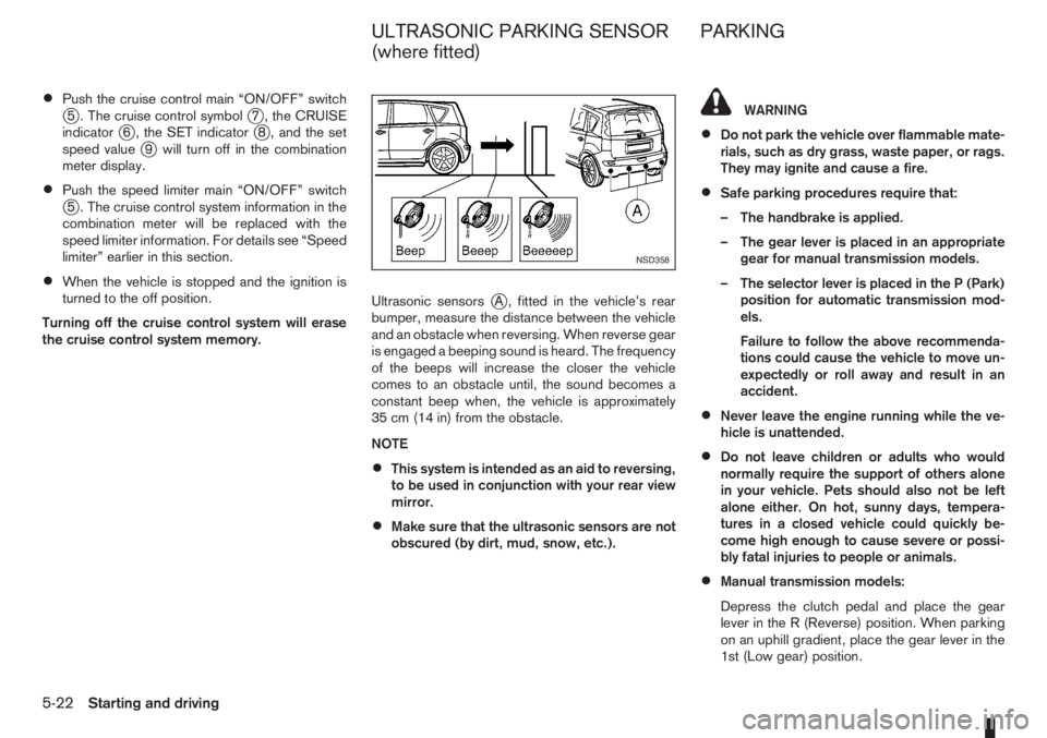
the cruise control system memory.Ultrasonic sensors
jA , fitted in the vehicle’s rear
bumper, measure the distance between the vehicle
and an obstacle when reversing. When reverse gear
is engaged a beeping sound is heard. The frequency
of the beeps will increase the closer the vehicle
comes to an obstacle until, the sound becomes a
constant beep when, the vehicle is approximately
35 cm (14 in) from the obstacle.
NOTE
•This system is intended as an aid to reversing,
to be used in conjunction with your rear view
mirror.
•Make sure that the ultrasonic sensors are not
obscured (by dirt, mud, snow, etc.).
WARNING
•Do not park the vehicle over flammable mate-
rials, such as dry grass, waste paper, or rags.
They may ignite and cause a fire.
•Safe parking procedures require that:
– The handbrake is applied.
– The gear lever is placed in an appropriate
gear for manual transmission models.
– The selector lever is placed in the P (Park)
position for automatic transmission mod-
els.
Failure to follow the above recommenda-
tions could cause the vehicle to move un-
expectedly or roll away and result in an
accident.
•Never leave the engine running while the ve-
hicle is unattended.
•Do not leave children or adults who would
normally require the support of others alone
in your vehicle. Pets should also not be left
alone either. On hot, sunny days, tempera-
tures in a closed vehicle could quickly be-
come high enough to cause severe or possi-
bly fatal injuries to people or animals.
•Manual transmission models:
Depress the clutch pedal and place the gear
lever in the R (Reverse) position. When parking
on an uphill gradient, place the gear lever in the
1st (Low gear) position.
NSD358
ULTRASONIC PARKING SENSOR
(where fitted)PARKING
5-22Starting and driving
Page 148 of 235
•Turn the ignition switch to the LOCK position
and remove the key/Intelligent Key (where fit-
ted).Your new vehicle was designed to be used primarily
to carry passengers and luggage.
Remember that towing a trailer will place additional
loads on your vehicle’s engine, drive-train, steering,
braking and other systems. Towing a trailer will also
exaggerate other conditions, such as sway caused
by crosswinds, rough road surfaces or passing
trucks. Driving style and speed must be adjusted
according to the circumstances. Before towing a
trailer, see a NISSAN dealer or qualified workshop
for an explanation of towing equipment and its
proper use.
OPERATING PRECAUTIONS
•Avoid towing a trailer during the running-in
schedule.
•Choose proper coupling devices (trailer hitch,
safety chain, roof carrier, etc.) for your vehicle
and trailer. These devices are available from a
NISSAN dealer or qualified workshop where you
can also obtain more detailed information about
trailer towing.
Heavy-duty kits are available at a NISSAN dealer
or qualified workshop.
•It is advisable to contact a NISSAN dealer or
qualified workshop for towing details, before
towing a trailer up steep slopes for long dis-
tances.
•Never allow the total trailer load (trailer weight
plus its cargo weight) to exceed the maximum
set for the coupling device.Contact a NISSAN dealer or qualified workshop
for more information on this matter.
•The trailer must be loaded so that heavy goods
are distributed over the axle and as low in the
trailer as possible. Poor load distribution can se-
riously affect the stability of the trailer and tow
vehicle.
•Do not exceed the maximum permitted vertical
load on the trailer hitch.
•Before driving, make sure that the lighting sys-
tem of the trailer works properly.
•Avoid abrupt starts, accelerations and stops.
•Avoid sharp turns and lane changes.
•Always drive your vehicle at a moderate speed.
•Always block the wheels on both vehicle and
trailer when parking. Apply the handbrake (where
fitted) on the trailer. Parking on a steep slope is
not recommended.
If parking on a steep slope is unavoidable it is
also advisable to put the vehicle into gear, or
select P (Park, AT models), and turn the front
wheels into the kerb (in addition to the other pre-
cautions described). Before parking on a steep
slope consider the incline (the towing weights
quoted are for a 12% slope).
•Follow the trailer manufacturer’s instructions.
TRAILER TOWING
5-24Starting and driving
Page 151 of 235
WARNING
•If the Electrically Power Assisted Steering
warning light (EPAS) illuminates while driv-
ing, the power assist for steering will be dis-
abled. Greater steering efforts are required to
operate the steering wheel, especially in
sharp turns and at low speed. Stop the ve-
hicle as soon as safely possible and contact a
NISSAN dealer or qualified workshop for fur-
ther assistance.
•In certain circumstances, factors external to
the EPAS system may contribute to the illumi-
nation of the warning light. If the warning light
illuminates, stop the vehicle as soon as safely
possible if driving. Turn the ignition switch to
the “OFF” position and wait for approximately
20 seconds, then turn the ignition switch to
the ON position again. If the light remains illu-
minated, we recommend you to contact a
NISSAN dealer or qualified workshop. See
“Warning/indicator lights and audible
reminders” in the “2. Instruments and
controls” section for further details regarding
the EPAS warning light.
The EPAS (Electrically Power Assisted Steering)
system is designed to assist steering.
The steering may appear to feel slightly stiff follow-
ing parking manoeuvres including a great deal of
steering. This is not a malfunction; it is caused by a
control system designed to prevent the motor fromoverheating. No servicing is required. The EPAS
system will return to normal operation the next time
the vehicle is driven.
Similarly, the EPAS system may not provide full as-
sistance during periods of reduced battery voltage
but will recover once normal battery voltage is re-
stored.
If the EPAS warning light comes on while the engine
is running, it may indicate that the EPAS system is
not working properly. As result greater steering ef-
forts are required to steer the steering wheel, espe-
cially in sharp turns and at low speeds. Have the
system checked by a NISSAN dealer or qualified
workshop as soon as possible.
NOTE
Incorrectly inflated tyres can lead to poor steer-
ing ability and make the driver suspect a steering
problem: keep the vehicle’s tyres inflated to the
correct pressure at all times.
CAUTION
Any malfunction or accident that could have dam-
aged the steering components (including actual
or attempted theft damage) should be reported
to a NISSAN dealer or qualified workshop.The brake system has two separate hydraulic cir-
cuits. If one circuit malfunctions, you will still have
braking ability with two wheels.
BRAKE PRECAUTIONS
Vacuum assisted brake
The brake booster aids braking by using engine
vacuum. If the engine stops or the drive belt is bro-
ken, you can stop the vehicle by depressing the
brake pedal. However, greater foot pressure on the
brake pedal will be required to stop the vehicle and
the stopping distance will be longer.
Wet brakes
When the vehicle is washed or driven through wa-
ter, the brakes may get wet. As a result, your brak-
ing distance will be longer and the vehicle may pull
to one side during braking.
To dry brakes, drive the vehicle at a safe speed
while lightly pressing the brake pedal to heat up the
brakes. Do this until the brakes return to normal.
Avoid driving the vehicle at high speeds until the
brakes function correctly.
Using the brakes
Avoid resting your foot on the brake pedal while
driving. This will overheat the brakes, wear out the
brake linings and pads faster and reduce fuel
economy performance.
To help reduce brake wear and to prevent the brakes
from overheating, reduce speed and downshift to a
lower gear before going down a slope or long down-
POWER STEERING SYSTEM BRAKE SYSTEM
Starting and driving5-27
Page 152 of 235
hill gradient. Overheated brakes may reduce brak-
ing performance and could result in loss of vehicle
control.
CAUTION
While driving on a slippery surface, be careful
when braking, accelerating or downshifting.
Abrupt braking actions or sudden acceleration
could cause the wheels to skid and result in an
accident.
Be aware that brakes will fade if repeated heavy
brake applications are made.
Driving uphill
When starting on a steep gradient, it is sometimes
difficult to operate the brake (AT models) or both the
brake and clutch (MT models). Use the handbrake
to hold the vehicle. Do not slip the clutch (MT mod-
els). When ready to start, slowly release the hand-
brake while depressing the accelerator pedal and
releasing the clutch (MT models) or depressing the
accelerator pedal (AT models).
Driving downhill
The engine braking action is effective for controlling
the vehicle while descending hills.
The gear lever (MT models) should be placed in a
gear position low enough to obtain sufficient engine
braking.
For AT models, the 2 (Second) or 1 (First) gear
should be selected.
ANTI-LOCK BRAKING SYSTEM (ABS)
WARNING
•The Anti-lock Braking System (ABS) is a so-
phisticated device, but it cannot prevent acci-
dents resulting from careless or dangerous
driving techniques. It can help maintain ve-
hicle control during braking on slippery sur-
faces. Remember that stopping distances
may also be longer on rough, gravel or snow
covered roads, or if you are using snow
chains. Always maintain a safe distance from
the vehicle in front of you. Ultimately, the
driver is responsible for safety.
•Tyre type and condition may also affect brak-
ing effectiveness.
– When replacing tyres, install the specified
size of tyres on all four wheels.
– When installing a spare tyre, make sure it
is the proper size and type as specified on
the tyre placard. See “Vehicle
identification” in the “9. Technical
information” section for the tyre placard
location.
– For detailed information, see “Wheels and
tyres” in the “8. Maintenance and
do-it-yourself” section.
The Anti-lock Braking System (ABS) controls the
brakes so that the wheels do not lock during hard
braking or when braking on slippery surfaces. The
system detects the rotation speed at each wheeland varies the brake fluid pressure to prevent each
wheel from locking and sliding. By preventing each
wheel from locking, the system helps the driver to
maintain steering control and helps to minimise
swerving and spinning on slippery surfaces.
Using the system
Depress the brake pedal and hold it down. Depress
the brake pedal with firm steady pressure, but do
not pump the brakes. The ABS will operate to pre-
vent the wheels from locking up. Steer the vehicle to
avoid obstacles.
WARNING
Do not pump the brake pedal. Doing so may in-
crease the stopping distance.
Self-test feature
The ABS includes electronic sensors, electric
pumps, hydraulic solenoids and a computer. The
computer has a built-in diagnostic feature that tests
the system each time you start the engine and move
the vehicle at a low speed in forward or reverse.
When the self-test occurs, you may hear a “clunk”
noise and/or feel a pulsation in the brake pedal. This
is normal and does not indicate a malfunction. If the
computer senses a malfunction, it switches the ABS
off and illuminates the ABS warning light on the
instrument panel. The brake system then operates
normally, but without anti-lock assistance.
If the ABS warning light illuminates during the self-
test or while driving, have the vehicle checked by a
NISSAN dealer or qualified workshop.
5-28Starting and driving
Page 155 of 235
NOTE
The ESP system cannot be switched off when
the ESP system is operating and the “SLIP” indi-
cator light (
) is blinking.
Push the ESP OFF switch again, or restart the en-
gine, to turn the system ON. See “Electronic Stabil-
ity Programme (ESP) system (where fitted)” earlier
in this section for operational details.
WARNING
•Whatever the conditions, drive with caution.
Accelerate and decelerate with great care. If
accelerating or decelerating too fast, the drive
wheels will lose even more traction.
•Allow more stopping distance in cold weather
driving. Braking should be started sooner than
on dry surfaces.
•Keep at a greater distance from the vehicle in
front of you on slippery roads.
•Wet ice (0°C, 32°F and freezing rain), very cold
snow and ice can be slick and very difficult to
drive on. The vehicle will have a lot less trac-
tion or grip under these conditions. Try to
avoid driving on wet ice until the road is salted
or sanded.
•Watch for slippery spots (black ice). These
may appear on an otherwise clear road in
shaded areas. If a patch of ice is seen ahead,
brake before driving on it. Try not to brake
while actually on the ice and avoid any sud-
den steering manoeuvres.
•Snow can trap dangerous exhaust gas under
your vehicle. Keep snow clear of the exhaust
pipe and from around your vehicle.
BATTERY
If the battery is not fully charged during extremely
cold weather conditions, the battery fluid may freeze
and damage the battery. To maintain maximum effi-ciency, the battery should be checked regularly. For
details, see “Battery” in the “8. Maintenance and
do-it-yourself” section.
ENGINE COOLANT
If the vehicle is to be left outside without anti-freeze,
drain the cooling system. Refill before operating the
vehicle. For details, see “Engine cooling system” in
the “8. Maintenance and do-it-yourself” section.
TYRE EQUIPMENT
1) The SUMMER tyres are of a tread design to pro-
vide superior performance on dry surfaces. How-
ever, the performance of these tyres will be sub-
stantially reduced in snowy and icy conditions. If
you operate your vehicle on snowy or icy roads,
NISSAN recommends the use of MUD & SNOW
or ALL SEASON tyres on all four wheels. Please
consult a NISSAN dealer or qualified workshop
for tyre type, size, speed rating and availability
information.
2) For additional traction on icy roads, studded
tyres may be used. However, some countries,
provinces and states prohibit their use. Check
applicable laws before installing studded tyres.
CAUTION
Skid and traction capabilities of studded snow
tyres on wet or dry surfaces may be poorer
than that of non-studded snow tyres.
3) Snow chains may be used, if desired. But the
use of snow chains may be prohibited in some
areas. Therefore, check the local laws before
COLD WEATHER DRIVING
Starting and driving5-31
Page 157 of 235
6In case of emergencyIn case of emergency
Spare tyre................................................................ 6-2
Temporary-use spare tyre ................................... 6-2
Flat tyre ................................................................... 6-3
Stopping the vehicle ........................................... 6-3
Changing flat tyre (Models with spare wheel,
where fitted) ....................................................... 6-3
Repairing flat tyre (Models with emergency
tyre puncture repair kit, where fitted) ................... 6-7Jump-starting ........................................................... 6-9
Push-starting ........................................................... 6-11
Engine overheat ....................................................... 6-11
Tow truck towing ..................................................... 6-12
Towing precautions ............................................ 6-12
Recommended towing ........................................ 6-13
Towing eye ......................................................... 6-13
Freeing the vehicle from sand, snow or mud ....... 6-14
Page 167 of 235
CAUTION
•Three-way catalyst equipped models should
not be started by pushing the vehicle as the
three-way catalyst may be damaged.
•Automatic transmission (AT) models cannot
be started by pushing the vehicle. This may
cause transmission damage.
•Never try to start the vehicle by towing it; when
the engine starts, the forward surge could
cause the vehicle to collide with the tow ve-
hicle.
WARNING
•Never continue driving if the engine of your
vehicle overheats. Doing so could cause a ve-
hicle fire.
•Never open the bonnet if steam is coming
out.
•Never remove the radiator cap (where fitted)
or engine coolant reservoir cap when the en-
gine is hot. If the radiator cap (where fitted) or
engine coolant reservoir cap is removed while
the engine is hot, pressurised hot water will
spurt out and possibly cause burning, scald-
ing or serious injury.
•If steam or coolant is coming out of the en-
gine, stand clear of the vehicle to prevent get-
ting injured.
•The engine cooling fan will start whenever the
coolant temperature exceeds preset degrees.
•Be careful not to allow your hands, hair, jewel-
lery or clothing to come into contact with, or
get caught in, the cooling fan or drive belts.
If the engine of your vehicle is overheating (indi-
cated by the engine coolant temperature warning
light (red)) or if you feel a lack of engine power,
detect an unusual noise, etc., proceed as follows:
1. Move and park the vehicle safely off the road and
away from traffic.
2. Turn on the hazard warning flasher lights.
3. Apply the handbrake.4. Shift the gear lever (M/T models) into the N (Neu-
tral) position [AT models, move the selector lever
to the P (Park) position].
DO NOT STOP THE ENGINE.
5. Open all windows.
6. Switch off the air conditioner system (where fit-
ted).
7. Set the heater or air conditioner temperature
control to maximum “HOT” and fan speed con-
trol to maximum speed.
8. Exit the vehicle.
9. Visually inspect and listen for steam or coolant
escaping from the radiator before opening the
bonnet. Wait until no steam or coolant can be
seen before proceeding.
10. Open the bonnet. For details, see “Bonnet
release” in the “3. Pre-driving checks and
adjustments” section.
11. Visually check if the cooling fan is running.
12. Visually check the radiator and radiator hoses
for leakage.
WARNING
If coolant is leaking, the cooling fan belt is
missing or loose or the cooling fan is not run-
ning, stop the engine.
PUSH-STARTING ENGINE OVERHEAT
In case of emergency6-11
Page 183 of 235
WARNING
•To avoid the danger of being scalded, never
change the coolant when the engine is hot.
•Avoid direct skin contact with used coolant. If
skin contact is made, wash thoroughly with
soap or hand cleaner and plenty of water as
soon as possible.
•Keep coolant out of reach of children and
pets.
NISSAN GREEN PROGRAM
Engine coolant must be disposed of properly.
Check your local regulations.
CR14DE or HR16DE engine
1. Set the heater or air conditioner temperature
control to the maximum “HOT” position.
2. Open the bonnet. For details, see “Bonnet
release” in the “3. Pre-driving checks and
adjustments” section.
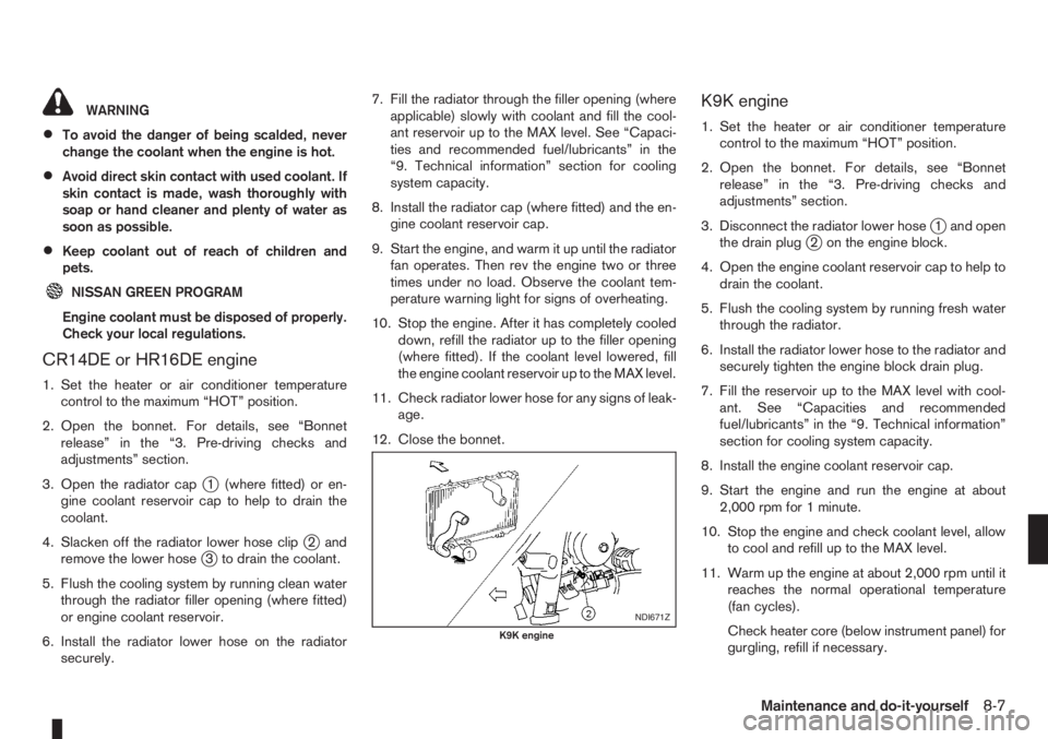
3. Open the radiator cap
j1 (where fitted) or en-
gine coolant reservoir cap to help to drain the
coolant.
4. Slacken off the radiator lower hose clip
j2and
remove the lower hosej3 to drain the coolant.
5. Flush the cooling system by running clean water
through the radiator filler opening (where fitted)
or engine coolant reservoir.
6. Install the radiator lower hose on the radiator
securely.7. Fill the radiator through the filler opening (where
applicable) slowly with coolant and fill the cool-
ant reservoir up to the MAX level. See “Capaci-
ties and recommended fuel/lubricants” in the
“9. Technical information” section for cooling
system capacity.
8. Install the radiator cap (where fitted) and the en-
gine coolant reservoir cap.
9. Start the engine, and warm it up until the radiator
fan operates. Then rev the engine two or three
times under no load. Observe the coolant tem-
perature warning light for signs of overheating.
10. Stop the engine. After it has completely cooled
down, refill the radiator up to the filler opening
(where fitted). If the coolant level lowered, fill
the engine coolant reservoir up to the MAX level.
11. Check radiator lower hose for any signs of leak-
age.
12. Close the bonnet.
K9K engine
1. Set the heater or air conditioner temperature
control to the maximum “HOT” position.
2. Open the bonnet. For details, see “Bonnet
release” in the “3. Pre-driving checks and
adjustments” section.
3. Disconnect the radiator lower hose
j1 and open
the drain plugj2 on the engine block.
4. Open the engine coolant reservoir cap to help to
drain the coolant.
5. Flush the cooling system by running fresh water
through the radiator.
6. Install the radiator lower hose to the radiator and
securely tighten the engine block drain plug.
7. Fill the reservoir up to the MAX level with cool-
ant. See “Capacities and recommended
fuel/lubricants” in the “9. Technical information”
section for cooling system capacity.
8. Install the engine coolant reservoir cap.
9. Start the engine and run the engine at about
2,000 rpm for 1 minute.
10. Stop the engine and check coolant level, allow
to cool and refill up to the MAX level.
11. Warm up the engine at about 2,000 rpm until it
reaches the normal operational temperature
(fan cycles).
Check heater core (below instrument panel) for
gurgling, refill if necessary.
NDI671Z
K9K engine
Maintenance and do-it-yourself8-7