wheel NISSAN NOTE 2012 User Guide
[x] Cancel search | Manufacturer: NISSAN, Model Year: 2012, Model line: NOTE, Model: NISSAN NOTE 2012Pages: 235, PDF Size: 2.29 MB
Page 53 of 235
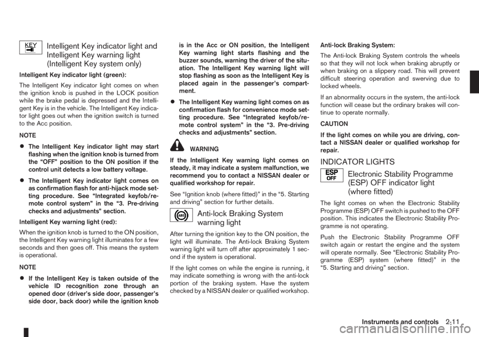
Intelligent Key indicator light and
Intelligent Key warning light
(Intelligent Key system only)
Intelligent Key indicator light (green):
The Intelligent Key indicator light comes on when
the ignition knob is pushed in the LOCK position
while the brake pedal is depressed and the Intelli-
gent Key is in the vehicle. The Intelligent Key indica-
tor light goes out when the ignition switch is turned
to the Acc position.
NOTE
•The Intelligent Key indicator light may start
flashing when the ignition knob is turned from
the “OFF” position to the ON position if the
control unit detects a low battery voltage.
•The Intelligent Key indicator light comes on
as confirmation flash for anti-hijack mode set-
ting procedure. See “Integrated keyfob/re-
mote control system” in the “3. Pre-driving
checks and adjustments” section.
Intelligent Key warning light (red):
When the ignition knob is turned to the ON position,
the Intelligent Key warning light illuminates for a few
seconds and then goes off. This means the system
is operational.
NOTE
•If the Intelligent Key is taken outside of the
vehicle ID recognition zone through an
opened door (driver’s side door, passenger’s
side door, back door) while the ignition knobis in the Acc or ON position, the Intelligent
Key warning light starts flashing and the
buzzer sounds, warning the driver of the situ-
ation. The Intelligent Key warning light will
stop flashing as soon as the Intelligent Key is
placed again in the passenger’s compart-
ment.
•The Intelligent Key warning light comes on as
confirmation flash for convenience mode set-
ting procedure. See “Integrated keyfob/re-
mote control system” in the “3. Pre-driving
checks and adjustments” section.
WARNING
If the Intelligent Key warning light comes on
steady, it may indicate a system malfunction, we
recommend you to contact a NISSAN dealer or
qualified workshop for repair.
See “Ignition knob (where fitted)” in the “5. Starting
and driving” section for further details.
Anti-lock Braking System
warning light
After turning the ignition key to the ON position, the
light will illuminate. The Anti-lock Braking System
warning light will turn off after approximately 1 sec-
ond if the system is operational.
If the light comes on while the engine is running, it
may indicate something is wrong with the anti-lock
portion of the braking system. Have the system
checked by a NISSAN dealer or qualified workshop.Anti-lock Braking System:
The Anti-lock Braking System controls the wheels
so that they will not lock when braking abruptly or
when braking on a slippery road. This will prevent
difficult steering operation and swerving due to
locked wheels.
If an abnormality occurs in the system, the anti-lock
function will cease but the ordinary brakes will con-
tinue to operate normally.
CAUTION
If the light comes on while you are driving, con-
tact a NISSAN dealer or qualified workshop for
repair.
INDICATOR LIGHTS
Electronic Stability Programme
(ESP) OFF indicator light
(where fitted)
The light comes on when the Electronic Stability
Programme (ESP) OFF switch is pushed to the OFF
position. This indicates the Electronic Stability Pro-
gramme is not operating.
Push the Electronic Stability Programme OFF
switch again or restart the engine and the system
will operate normally. See “Electronic Stability Pro-
gramme (ESP) system (where fitted)” in the
“5. Starting and driving” section.
Instruments and controls2-11
Page 54 of 235
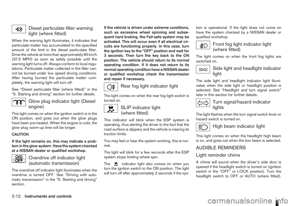
Diesel particulate filter warning
light (where fitted)
When the warning light illuminates, it indicates that
particulate matter has accumulated to the specified
amount of the limit in the diesel particulate filter.
Drive the vehicle at more than approximately 60 km/h
(37.5 MPH) as soon as safely possible until the
warning light turns off. Always conform to local regu-
lations. Particulate matter collected in the filter can-
not be burned under low speed driving conditions.
After having burned the particulate matter com-
pletely, the warning light will turn off.
See “Diesel particulate filter (where fitted)” in the
“5. Starting and driving” section for further details.
Glow plug indicator light (Diesel
engine)
This light comes on when the ignition switch is in the
ON position, and goes out when the glow plugs
have been pre-heated. When the engine is cold, the
glow plug warm-up time will be longer.
CAUTION
If the light remains on, this may indicate a prob-
lem in the glow system. Have the system checked
at a NISSAN dealer or qualified workshop.
Overdrive off indicator light
(automatic transmission)
The overdrive off indicator light illuminates when the
overdrive is turned OFF. See “Driving with auto-
matic transmission” in the “5. Starting and driving”
section.If the vehicle is driven under extreme conditions,
such as excessive wheel spinning and subse-
quent hard braking, the Fail-safe system may be
activated. This will occur even if all electrical cir-
cuits are functioning properly. In this case, turn
the ignition key to the “OFF” position and wait for
3 seconds. Then turn the key back to the ON
position. The vehicle should return to its normal
operating condition. If it does not return to its
normal operating condition have a NISSAN dealer
or qualified workshop check the transmission
and repair if necessary.
Rear fog light indicator light
The light comes on when the rear fog light switch is
turned on.
SLIP indicator light
(where fitted)
This indicator will blink when the ESP system is
operating, thus alerting the driver to the fact that the
road surface is slippery and the vehicle is nearing its
traction limits.
You may feel or hear the system working, this is nor-
mal.
The light will blink for a few seconds after the ESP
system stops limiting wheel spin.
The
indicator light also comes on when you
turn the ignition switch to the ON position. The light
will turn off after approximately 2 seconds if the sys-tem is operational. If the light does not come on
have the system checked by a NISSAN dealer or
qualified workshop.
Front fog light indicator light
(where fitted)
The light comes on when the front fog lights are
switched on.
Side light and headlight indicator
light
The side light and headlight indicator light illumi-
nates when the side light or headlight position is
selected. See “Headlight and turn signal switch”
later in this section for further details.
Turn signal/hazard indicator
lights
The light flashes when the turn signal switch lever or
hazard switch is turned on.
High beam indicator light
This light comes on when the headlight high beam
is on, and goes out when the low beam is selected.
AUDIBLE REMINDERS
Light reminder chime
A chime will sound when the driver’s side door is
opened if the headlight switch is turned on (ignition
switch in the “OFF” or LOCK position). Turn the
headlight switch to OFF or AUTO (where fitted),
2-12Instruments and controls
Page 60 of 235
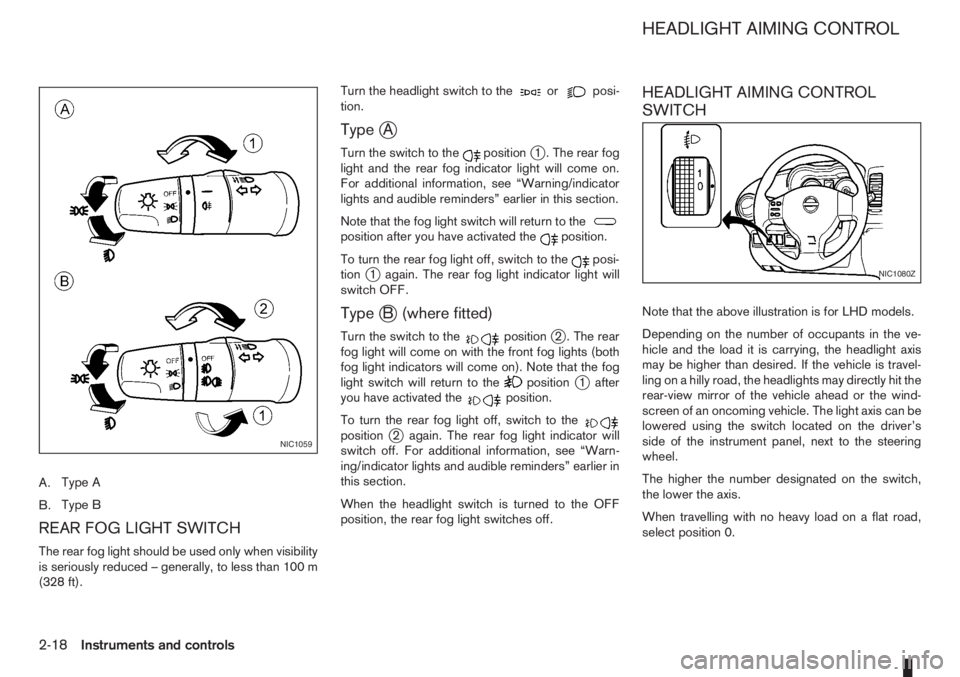
A.Type A
B.Type B
REAR FOG LIGHT SWITCH
The rear fog light should be used only when visibility
is seriously reduced – generally, to less than 100 m
(328 ft).Turn the headlight switch to the
orposi-
tion.
TypejA
Turn the switch to thepositionj1 . The rear fog
light and the rear fog indicator light will come on.
For additional information, see “Warning/indicator
lights and audible reminders” earlier in this section.
Note that the fog light switch will return to the
position after you have activated theposition.
To turn the rear fog light off, switch to the
posi-
tionj1 again. The rear fog light indicator light will
switch OFF.
TypejB (where fitted)
Turn the switch to thepositionj2 . The rear
fog light will come on with the front fog lights (both
fog light indicators will come on). Note that the fog
light switch will return to the
positionj1 after
you have activated theposition.
To turn the rear fog light off, switch to the
positionj2 again. The rear fog light indicator will
switch off. For additional information, see “Warn-
ing/indicator lights and audible reminders” earlier in
this section.
When the headlight switch is turned to the OFF
position, the rear fog light switches off.
HEADLIGHT AIMING CONTROL
SWITCH
Note that the above illustration is for LHD models.
Depending on the number of occupants in the ve-
hicle and the load it is carrying, the headlight axis
may be higher than desired. If the vehicle is travel-
ling on a hilly road, the headlights may directly hit the
rear-view mirror of the vehicle ahead or the wind-
screen of an oncoming vehicle. The light axis can be
lowered using the switch located on the driver’s
side of the instrument panel, next to the steering
wheel.
The higher the number designated on the switch,
the lower the axis.
When travelling with no heavy load on a flat road,
select position 0.
NIC1059
NIC1080Z
HEADLIGHT AIMING CONTROL
2-18Instruments and controls
Page 61 of 235
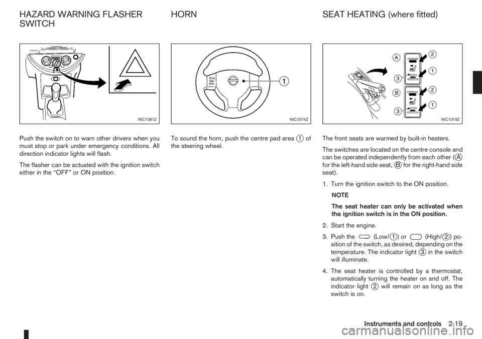
Push the switch on to warn other drivers when you
must stop or park under emergency conditions. All
direction indicator lights will flash.
The flasher can be actuated with the ignition switch
either in the “OFF” or ON position.To sound the horn, push the centre pad areaj1of
the steering wheel.The front seats are warmed by built-in heaters.
The switches are located on the centre console and
can be operated independently from each other (
jA
for the left-hand side seat,jB for the right-hand side
seat).
1. Turn the ignition switch to the ON position.
NOTE
The seat heater can only be activated when
the ignition switch is in the ON position.
2. Start the engine.
3. Push the
(Low/j1)or(High/j2)po-
sition of the switch, as desired, depending on the
temperature. The indicator light
j3 in the switch
will illuminate.
4. The seat heater is controlled by a thermostat,
automatically turning the heater on and off. The
indicator light
j2 will remain on as long as the
switch is on.
NIC1081ZNIC1074ZNIC1319Z
HAZARD WARNING FLASHER
SWITCHHORN SEAT HEATING (where fitted)
Instruments and controls2-19
Page 71 of 235
3Pre-driving checks and adjustmentsPre-driving checks and adjustments
Keys ........................................................................ 3-2
Integrated keyfob/remote control system .................. 3-3
Using the remote keyless entry system ................ 3-3
Locking the doors ............................................... 3-3
Unlocking the doors – convenience mode ........... 3-4
Unlocking the doors – anti-hijack mode ............... 3-4
Switching from convenience mode to
anti-hijack mode.................................................. 3-4
Keyfob operation failure ...................................... 3-4
Intelligent Key system (where fitted) ......................... 3-5
Locking/unlocking .............................................. 3-5
Starting the engine with the Intelligent Key .......... 3-6
Door locks ............................................................... 3-6
Super Lock System (Right-hand drive models) .... 3-6
Vehicle dead battery – left-hand side door
handle ................................................................ 3-7
Locking with power door lock switch .................. 3-7Child safety rear door lock .................................. 3-8
Back door lock ................................................... 3-8
Security system ....................................................... 3-9
NISSAN Anti-Theft System (NATS)..................... 3-9
Bonnet release ........................................................ 3-10
Fuel filler lid ............................................................. 3-11
Fuel filler lid opener lever .................................... 3-11
Fuel filler cap ...................................................... 3-11
Handbrake lever ...................................................... 3-11
Tilting steering wheel ............................................... 3-12
Mirrors..................................................................... 3-12
Inside rear-view mirror ........................................ 3-12
Outside rear-view mirrors.................................... 3-12
Vanity mirror ....................................................... 3-13
Rear parcel shelf...................................................... 3-14
Rear parcel shelf removal.................................... 3-14
Rear parcel shelf installation................................ 3-14
Page 82 of 235
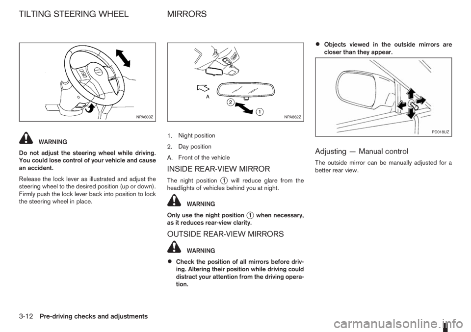
WARNING
Do not adjust the steering wheel while driving.
You could lose control of your vehicle and cause
an accident.
Release the lock lever as illustrated and adjust the
steering wheel to the desired position (up or down).
Firmly push the lock lever back into position to lock
the steering wheel in place.1.Night position
2.Day position
A.Front of the vehicle
INSIDE REAR-VIEW MIRROR
The night positionj1 will reduce glare from the
headlights of vehicles behind you at night.
WARNING
Only use the night position
j1 when necessary,
as it reduces rear-view clarity.
OUTSIDE REAR-VIEW MIRRORS
WARNING
•Check the position of all mirrors before driv-
ing. Altering their position while driving could
distract your attention from the driving opera-
tion.
•Objects viewed in the outside mirrors are
closer than they appear.
Adjusting — Manual control
The outside mirror can be manually adjusted for a
better rear view.
NPA600ZNPA862Z
PD018UZ
TILTING STEERING WHEEL MIRRORS
3-12Pre-driving checks and adjustments
Page 85 of 235
4Heater and air conditioner, and audio systemHeater and air conditioner, and audio system
Vents ....................................................................... 4-2
Side vents .......................................................... 4-2
Centre vents ....................................................... 4-2
Heater and air conditioner operation ........................ 4-2
Manual air conditioner......................................... 4-3
Automatic air conditioner (where fitted) ............... 4-8
Audio system ........................................................... 4-10
Audio operation precautions ............................... 4-10
Antenna .............................................................. 4-16
LW-MW-FM radio with CD player (where fitted) ...... 4-16
Anti-theft system ................................................. 4-16
Audio main operation .......................................... 4-17
Radio operation .................................................. 4-19
User set up menu ............................................... 4-21
Compact disc (CD) player operation ................... 4-22
FM AM radio with CD player (where fitted) .............. 4-23
Anti-theft system ................................................. 4-23
Audio main operation .......................................... 4-24
Radio operation .................................................. 4-25SETUP button .................................................... 4-26
Compact Disc (CD) operation ............................ 4-27
AUX socket ........................................................ 4-29
USB Memory operation ...................................... 4-29
iPod® player operation ....................................... 4-30
Bluetooth® operation.......................................... 4-31
Bluetooth® mobile phone feature ........................ 4-33
AM-FM radio with CD player and navigation
(where fitted) ........................................................... 4-34
Audio jack socket (AUX) (where fitted) ..................... 4-34
Mobile phone integration (where fitted) .................... 4-34
Bluetooth® mobile phone feature ........................ 4-34
Hands-free telephone control .............................. 4-36
Steering wheel switches (where fitted) ................ 4-38
Steering wheel switches for audio control (where
fitted) ....................................................................... 4-38
Main operation .................................................... 4-38
Car phone or CB radio ............................................ 4-39
Page 119 of 235
Bluetooth®is a wireless radio communication stan-
dard. This system offers a hands-free facility for your
mobile telephone to enhance driving comfort.
In order to use your mobile phone with the Blue-
tooth
®of the audio system, the mobile phone must
first be setup. For details, see “BLUETOOTH®
settings” later in this section or “BLUETOOTH®
settings” earlier in this section. Once it has been
setup, the hands-free mode is automatically acti-
vated on the registered mobile phone (via Blue-
tooth
®) when it comes into range.
A notification message appears on the audio display
when the phone is connected, when an incoming
call is being received, as well as when a call is initi-
ated.
When a call is active, the audio system, microphone
(located in the ceiling in front of the rear view mir-
ror), and steering wheel switches enable hands-free
communication.
If the audio system is in use at the time, the radio,
CD, or AUX source mode will be muted and will stay
muted until the active call has ended.
The Bluetooth
®system may be not be able to con-
nect with your mobile phone for the following rea-
sons:
•The mobile phone is too far away from the ve-
hicle.
•The Bluetooth®mode on your mobile phone has
not been activated.
•Your mobile phone has not been paired with the
Bluetooth®system of the audio unit.
•The mobile phone does not support Bluetooth®
technology (BT Core v2.0).
NOTE
•For models with NISSAN Connect (Audio with
Navigation system) see the separately pro-
vided Owner’s Manual.
•For details, see your mobile phone’s Owner’s
Manual.
•For assistance with your mobile phone inte-
gration, please visit your local NISSAN dealer.
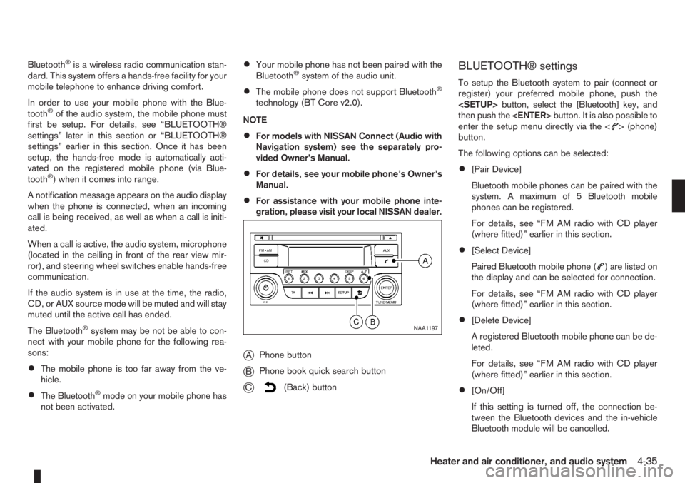
jAPhone button
jBPhone book quick search button
jC(Back) button
BLUETOOTH® settings
To setup the Bluetooth system to pair (connect or
register) your preferred mobile phone, push the
then push the
enter the setup menu directly via the <
> (phone)
button.
The following options can be selected:
•[Pair Device]
Bluetooth mobile phones can be paired with the
system. A maximum of 5 Bluetooth mobile
phones can be registered.
For details, see “FM AM radio with CD player
(where fitted)” earlier in this section.
•[Select Device]
Paired Bluetooth mobile phone (
) are listed on
the display and can be selected for connection.
For details, see “FM AM radio with CD player
(where fitted)” earlier in this section.
•[Delete Device]
A registered Bluetooth mobile phone can be de-
leted.
For details, see “FM AM radio with CD player
(where fitted)” earlier in this section.
•[On/Off]
If this setting is turned off, the connection be-
tween the Bluetooth devices and the in-vehicle
Bluetooth module will be cancelled.
NAA1197
Heater and air conditioner, and audio system4-35
Page 120 of 235
For details, see “FM AM radio with CD player
(where fitted)” earlier in this section.
When successfully paired, a notification message
will be displayed. During the connection the follow-
ing status icons will be displayed (top left of dis-
play): Signal strength (
), Battery status (), and
Bluetooth ().
*: If the low battery message comes on, the Blue-
tooth® device must be recharged soon.
HANDS-FREE TELEPHONE
CONTROL
The hands-free mode can be operated using the
telephone<>button on the audio system, or
(where fitted) on the steering wheel.
Initiating a call
A call can be initiated using one of the following
methods:
– Redial
– Phone book
– Manual dialling
– Missed calls
– Dialled calls
– Received callsRedial:
To redial or call the last number dialled, press<
>
for more than 2 seconds.
Making a call from the phone book:
Once the Bluetooth
®connection has been made,
between the registered mobile phone and the audio
system, phone book data will be transferred auto-
matically to the audio system. The transfer may take
a while before completion.
NOTE
Phone book data will be erased when:
•Switching to another registered mobile
phone.
•Mobile phone is disconnected.
•The registered mobile phone is deleted from
the audio system.
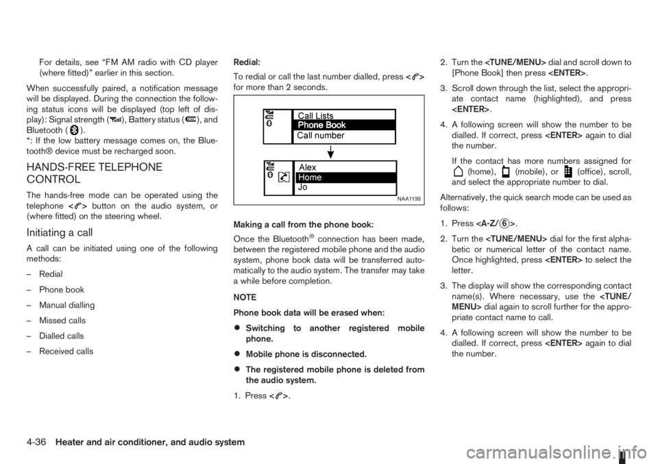
1. Press<
>.2. Turn the
[Phone Book] then press
3. Scroll down through the list, select the appropri-
ate contact name (highlighted), and press
4. A following screen will show the number to be
dialled. If correct, press
the number.
If the contact has more numbers assigned for
(home),(mobile), or(office), scroll,
and select the appropriate number to dial.
Alternatively, the quick search mode can be used as
follows:
1. Press
2. Turn the
betic or numerical letter of the contact name.
Once highlighted, press
letter.
3. The display will show the corresponding contact
name(s). Where necessary, use the
priate contact name to call.
4. A following screen will show the number to be
dialled. If correct, press
the number.
NAA1199
4-36Heater and air conditioner, and audio system
Page 122 of 235
![NISSAN NOTE 2012 User Guide •[#123] — Use this item to enter numbers during
a call. For example, if directed by an automated
phone system to dial an extension number the
system will send the tone associated with the
selected NISSAN NOTE 2012 User Guide •[#123] — Use this item to enter numbers during
a call. For example, if directed by an automated
phone system to dial an extension number the
system will send the tone associated with the
selected](/img/5/56792/w960_56792-121.png)
•[#123] — Use this item to enter numbers during
a call. For example, if directed by an automated
phone system to dial an extension number the
system will send the tone associated with the
selected number.
•[] — Use this item (the transfer handset com-
mand) to transfer the call from the audio system
to your mobile phone.
To transfer the call back to hands-free via the
audio system select [
].
STEERING WHEEL SWITCHES
(where fitted)
j
1Telephone button
j2Volume control buttons
The hands-free mode can be operated using the
steering wheel switches.
Volume control buttons
The volume control buttons allow you to adjust the
volume of the speakers by pressing the<+>or<
—>button.
Telephone button
The phone <> button allows you to:
•Accept an incoming call by pressing<>once.
•Reject an incoming call by pressing<>for
more than 2 seconds during the incoming call.
•End an active call by pressing the<>button
once.
•Redial the last outgoing call by pressing the<>
button for more than 2 seconds.
MAIN OPERATION
A.Source button
B.Volume control buttons
C.
(INFO) button
D.Scrolling switch
A.
(INFO) button
B.Volume control buttons
NAA1020Z
NAA898Z
Type A
NAA1010Z
Type B
STEERING WHEEL SWITCHES
FOR AUDIO CONTROL
(where fitted)
4-38Heater and air conditioner, and audio system