trailer NISSAN PATHFINDER 2021 Owners Manual
[x] Cancel search | Manufacturer: NISSAN, Model Year: 2021, Model line: PATHFINDER, Model: NISSAN PATHFINDER 2021Pages: 482, PDF Size: 5.33 MB
Page 215 of 482
∙ Do not fill a portable fuel container inthe vehicle or trailer. Static electricity
can cause an explosion of flammable
liquid, vapor or gas in any vehicle or
trailer. To reduce the risk of serious
injury or death when filling portable
fuel containers:
– Always place the container on the ground when filling.
– Do not use electronic devices when filling.
– Keep the pump nozzle in contact with the container while you are
filling it.
– Use only approved portable fuel containers for flammable liquid.
Page 323 of 482
∙ The system may not detect the ve-hicle in front of you in certain road or
weather conditions. To avoid acci-
dents, never use the ICC system under
the following conditions:
– On roads where the traffic is heavy or there are sharp curves
– On slippery road surfaces such as on ice or snow, etc.
– During bad weather (rain, fog, snow, etc.)
– When rain, snow or dirt adhere to the bumper around the distance
sensor
– On steep downhill roads (the ve- hicle may go beyond the set ve-
hicle speed and frequent braking
may result in overheating the
brakes)
– On repeated uphill and downhill roads
– When traffic conditions make it dif- ficult to keep a proper distance be-
tween vehicles because of fre-
quent acceleration or deceleration – Interference by other radar
sources
∙ Do not use the ICC system if you are towing a trailer. The system may not
detect a vehicle ahead.
∙ In some road or traffic conditions, a vehicle or object can unexpectedly
come into the sensor detection zone
and cause automatic braking. Always
stay alert and avoid using the ICC sys-
tem where not recommended in this
warning section.
The radar sensor will not detect the follow-
ing objects: ∙ Stationary and slow moving vehicles
∙ Pedestrians or objects in the roadway
∙ Oncoming vehicles in the same lane
∙ Motorcycles traveling offset in the travel lane
The following are some conditions in which
the sensor cannot properly detect a ve-
hicle ahead and the system may not oper-
ate properly: ∙ When snow or road spray from traveling vehicles reduces the sensor’s detection. ∙ When excessively heavy baggage is
loaded in the rear seat or cargo area of
your vehicle.
The ICC system is designed to automati-
cally check the sensor’s operation within
the limitations of the system.
The detection zone of the ICC sensor is
limited. A vehicle ahead must be in the de-
tection zone for the vehicle-to-vehicle dis-
tance detection mode to maintain the se-
lected distance from the vehicle ahead.
A vehicle ahead may move outside of the
detection zone due to its position within
the same lane of travel. Motorcycles may
not be detected in the same lane ahead if
they are traveling offset from the centerline
of the lane. A vehicle that is entering the
lane ahead may not be detected until the
vehicle has completely moved into the
lane.
If this occurs, the ICC system may warn
you by blinking the system indicator and
sounding the chime. The driver may
have to manually control the proper dis-
tance away from vehicle traveling ahead.
Starting and driving5-53
Page 418 of 482
∙ Tire tread of the TEMPORARY USEONLY spare tire will wear at a faster
rate than the standard tire. Replace
the spare tire as soon as the tread
wear indicators appear.
∙ Do not use the spare tire on other vehicles.
∙ Do not use more than one spare tire at the same time.
∙ Do not tow a trailer when the TEMPO- RARY USE ONLY spare tire is installed.
Page 439 of 482
Oil which may contain foreign matter or
has been previously used should not be
used.
Oil viscosity
The engine oil viscosity or thickness
changes with temperature. Because of
this, it is important to select the engine oil
viscosity based on the temperatures at
which the vehicle will be operated before
the next oil change. Choosing an oil viscos-
ity other than that recommended could
cause serious engine damage.
Selecting the correct oil filter
Your new NISSAN vehicle is equipped with a
high-quality Genuine NISSAN oil filter. When
replacing, use a Genuine NISSAN oil filter or
its equivalent for the reason described in
“Change intervals.”
Change intervals
The oil and oil filter change intervals for
your engine are based on the use of the
specified quality oils and filters. Using en-
gine oil and filters that are not of the speci-
fied quality, or exceeding recommended oil
and filter change intervals could reduce
engine life. Damage to the engine caused
by improper maintenance or use of incor-rect oil and filter quality and/or viscosity is
not covered by the NISSAN New Vehicle
Limited Warranty.
Your engine was filled with a high-quality
engine oil when it was built. You do not have
to change the oil before the first recom-
mended change interval. Oil and filter
change intervals depend upon how you
use your vehicle.
Operation under the following conditions
may require more frequent oil and filter
changes:
∙ repeated short distance driving at cold outside temperatures
∙ driving in dusty conditions
∙ extensive idling
∙ towing a trailer
∙ stop and go commuting
For additional information, refer to the
“Maintenance and schedules” section of
this manual.
AIR CONDITIONER SYSTEM
REFRIGERANT AND OIL
RECOMMENDATIONS
The air conditioner system in your
NISSAN vehicle must be charged with the
refrigerant HFC-134a (R-134a) and the oil,
NISSAN A/C system oil Type DH-PS or the
exact equivalents.
Page 445 of 482
WARNING
∙ It is extremely dangerous to ride in a cargo area inside a ve-
hicle. In a collision, people riding
in these areas are more likely to
be seriously injured or killed.
∙ Do not allow people to ride in any area of your vehicle that is
not equipped with seats and
seat belts.
∙ Be sure everyone in your vehicle is in a seat and using a seat belt
properly.
TERMS
It is important to familiarize yourself
with the following terms before
loading your vehicle:
∙ Curb Weight (actual weight of your vehicle) - vehicle weight in-
cluding: standard and optional
equipment, fluids, emergency
tools, and spare tire assembly.
This weight does notinclude
passengers and cargo. ∙ GVW (Gross Vehicle Weight) - curb
weight plus the combined weight
of passengers and cargo.
∙ GVWR (Gross Vehicle Weight Rat- ing) - maximum total combined
weight of the unloaded vehicle,
passengers, luggage, hitch, trailer
tongue load and any other op-
tional equipment. This informa-
tion is located on the
F.M.V.S.S./C.M.V.S.S. certification
label.
∙ GAWR (Gross Axle Weight Rating) - maximum weight (load) limit
specified for the front or rear axle.
This information is located on the
F.M.V.S.S./C.M.V.S.S. certification
label.
∙ GCWR (Gross Combined Weight rating) - The maximum total
weight rating of the vehicle, pas-
sengers, cargo, and trailer. ∙ Vehicle Capacity Weight, Load
limit, Total load capacity - maxi-
mum total weight limit specified
of the load (passengers and
cargo) for the vehicle. This is the
maximum combined weight of
occupants and cargo that can be
loaded into the vehicle. If the ve-
hicle is used to tow a trailer, the
trailer tongue weight must be in-
cluded as part of the cargo load.
This information is located on the
Tire and Loading Information la-
bel.
∙ Cargo capacity - permissible weight of cargo, the subtracted
weight of occupants from the
load limit.
VEHICLE LOADING INFORMATION
Technical and consumer information10-13
Page 449 of 482
WARNING
Overloading or improper loading of a
trailer and its cargo can adversely affect
vehicle handling, braking and perfor-
mance and may lead to accidents.
Page 450 of 482
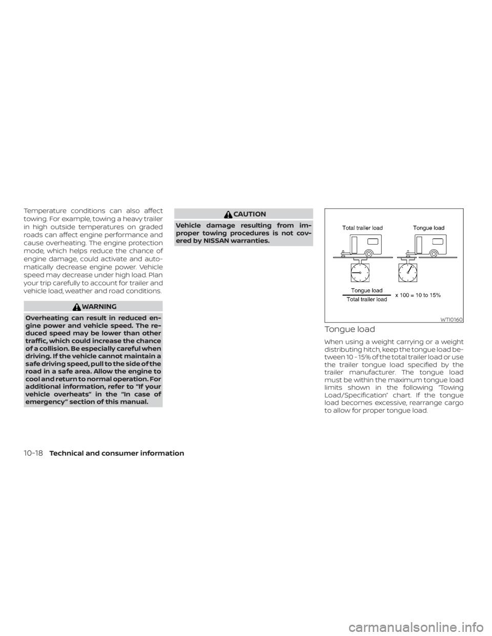
Temperature conditions can also affect
towing. For example, towing a heavy trailer
in high outside temperatures on graded
roads can affect engine performance and
cause overheating. The engine protection
mode, which helps reduce the chance of
engine damage, could activate and auto-
matically decrease engine power. Vehicle
speed may decrease under high load. Plan
your trip carefully to account for trailer and
vehicle load, weather and road conditions.
Page 452 of 482
Also weigh the front and rear axles on the
scale to make sure the Front Gross Axle
Weight and Rear Gross Axle Weight are not
more than Front Gross Axle Weight and
Rear Gross Axle Weight on the
F.M.V.S.S./C.M.V.S.S. certification label. The
cargo in the trailer and vehicle may need to
be moved or removed to meet the speci-
fied ratings.
Example:∙ Gross Vehicle Weight (GVW) as weighed on a scale - including passengers, cargo
and hitch - 6,350 lbs. (2,880 kg).
∙ Gross Vehicle Weight Rating (GVWR) from F.M.V.S.S./C.M.V.S.S. certification la-
bel - 7,250 lbs. (3,289 kg).
∙ Gross Combined Weight Rating (GCWR) from “Towing Load/Specification" chart
- 15,100 lbs. (6,849 kg).
∙ Maximum Trailer towing capacity from “Towing Load/Specification" chart -
9,100 lbs. (4,128 kg).
Page 454 of 482
WARNING
Trailer hitch components have specific
weight ratings. Your vehicle may be ca-
pable of towing a trailer heavier than the
weight rating of the hitch components.
Never exceed the weight rating of the
hitch components. Doing so can cause se-
rious personal injury or property damage.
Hitch ball
Choose a hitch ball of the proper size and
weight rating for your trailer:∙ The required hitch ball size is stamped on most trailer couplers. Most hitch
balls also have the size printed on the
top of the ball.
∙ Choose the proper class hitch ball based on the trailer weight.
∙ The diameter of the threaded shank of the hitch ball must be matched to the
ball mount hole diameter. The hitch ball
shank should be no more than 1/16”
smaller than the hole in the ball mount.
∙ The threaded shank of the hitch ball must be long enough to be properly
secured to the ball mount. There should
be at least 2 threads showing beyond
the lock washer and nut.
Ball mount
The hitch ball is attached to the ball mount
and the ball mount is inserted into the
hitch receiver. Choose a proper class ball
mount based on the trailer weight. Addi-
tionally, the ball mount should be chosen to
keep the trailer tongue level with the
ground.
Weight carrying hitches
A weight carrying or “dead weight” ball
mount is one that is designed to carry the
whole amount of tongue weight and gross
weight directly on the ball mount and on
the receiver.
Weight distribution hitch
This type of hitch is also called a “load-
leveling” or “equalizing” hitch. A set of bars
attach to the ball mount and to the trailer
to distribute the tongue weight (hitch
weight) of your trailer. Many vehicles can’t
carry the full tongue weight of a given
trailer, and need some of the tongue
weight transferred through the frame and
pushing down on the front wheels. This
gives stability to the tow vehicle. A weight-distributing hitch system (Class
IV) is recommended if you plan to tow trail-
ers with a maximum weight over 5,000 lbs.
(2,268 kg). Check with the trailer and towing
equipment manufacturers to determine if
they recommend the use of a weight-
distributing hitch system.
NOTE:
A weight-distributing hitch system may
affect the operation of trailer surge
brakes. If you are considering use of a
weight-distributing hitch system with a
surge brake-equipped trailer, check with
the surge brake, hitch or trailer manufac-
turer to determine if and how this can be
done.
Follow the instructions provided by the
manufacturer for installing and using the
weight-distributing hitch system.
General set-up instructions are as follows:
1. Park unloaded vehicle on a level sur- face. With the ignition on and the doors
closed, allow the vehicle to stand for
several minutes so that it can level.
2. Measure the height of a reference point on the front and rear bumpers at the
center of the vehicle.
10-22Technical and consumer information
Page 455 of 482
3. Attach the trailer to the vehicle and ad-just the hitch equalizers so that the
front bumper height is within 0 -
.5 inches (0 – 13 mm) of the reference
height measured in step 2. The rear
bumper should be no higher than the
reference height measured in step 2.