load NISSAN PATHFINDER 2022 Owner´s Manual
[x] Cancel search | Manufacturer: NISSAN, Model Year: 2022, Model line: PATHFINDER, Model: NISSAN PATHFINDER 2022Pages: 647, PDF Size: 8.48 MB
Page 125 of 647
For additional information, see “Hill descent
control switch” (P. 2-89) or “Hill descent con-
trol system” (P. 5-181).
Low tire pressure warning
light (if so equipped)
Your vehicle is equipped with a Tire Pres-
sure Monitoring System (TPMS) that moni-
tors the tire pressure of all tires except the
spare.
The low tire pressure warning light warns
of low tire pressure or indicates that the
TPMS is not functioning properly.
Af ter the ignition switch is placed in the ON
position, this light illuminates for about 1
second and turns off.
Low tire pressure warning
If the vehicle is being driven with low tire
pressure, the warning light will illumi-
nate. A “Tire Pressure Low - Add Air”
warning also appears in the vehicle in-
formation display.
When the low tire pressure warning light
illuminates, you should stop and adjust
the tire pressure of all four tires to the
recommended COLD tire pressure shown
on the Tire and Loading Information la-
bel located in the driver's door opening.The low tire pressure warning light does
not automatically turn off when the tire
pressure is adjusted. Af ter the tire is in-
flated to the recommended pressure,
the vehicle must be driven at speeds
above 16 mph (25 km/h) to activate the
TPMS and turn off the low tire pressure
warning light. Use a tire pressure gauge
to check the tire pressure.
The “Tire Pressure Low - Add Air” warning
appears each time the ignition switch is
placed in the ON position as long as the low
tire pressure warning light remains
illuminated.
For additional information, see “Vehicle in-
formation display–7 inch (18 cm) Type A”
(P. 2-22) or “Vehicle information display—12.3
inch (31 cm) Type B” (P. 2-45), “Tire Pressure
Monitoring System (TPMS)” (P. 5-5) or (P. 6-3).
TPMS malfunction
If the TPMS is not functioning properly, the
low tire pressure warning light will flash for
approximately 1 minute when the ignition
switch is placed in the ON position. The
light will remain on af ter 1 minute. Have the
system checked. It is recommended that
you visit a NISSAN dealer for this service.
The "Tire Pressure Low — Add Air" warning
does not appear if the low tire pressurewarning light illuminates to indicate a
TPMS malfunction.
For additional information, see “Tire Pres-
sure Monitoring System (TPMS)” (P. 5-5) and
“Tire pressure” (P. 8-29).
WARNING
• Radio waves could adversely affect
electric medical equipment. Those
who use a pacemaker should contact
the electric medical equipment
manufacturer for the possible influ-
ences before use.
• If the light does not illuminate with
the ignition switch placed in the ON
position, have the vehicle checked as
soon as possible. It is recommended
that you visit a NISSAN dealer for this
service.
2-18Instruments and controls
Page 126 of 647
•If the light illuminates while driving,
avoid sudden steering maneuvers or
abrupt braking, reduce vehicle
speed, pull off the road to a safe loca-
tion and stop the vehicle as soon as
possible. Driving with under-inflated
tires may permanently damage the
tires and increase the likelihood of
tire failure. Serious vehicle damage
could occur and may lead to an acci-
dent and could result in serious per-
sonal injury or death. Check the tire
pressure for all four tires. Adjust the
tire pressure to the recommended
COLD tire pressure shown on the Tire
and Loading Information label lo-
cated in the driver’s door opening to
turn the low tire pressure warning
light off. If the light still illuminates
while driving af ter adjusting the tire
pressure, a tire may be flat or the
TPMS may be malfunctioning. If you
have a flat tire, replace it with a spare
tire as soon as possible. If no tire is
flat and all tires are properly inflated,
have the vehicle checked. It is recom-
mended that you visit a NISSAN
dealer for this service. •
When using a wheel without the
TPMS such as the spare tire, the TPMS
will not function and the low tire
pressure warning light will flash for
approximately 1 minute. The light will
remain on af ter 1 minute. Have your
tires replaced and/or TPMS system
reset as soon as possible. It is recom-
mended that you visit a NISSAN
dealer for these services.
• Replacing tires with those not origi-
nally specified by NISSAN could af-
fect the proper operation of the
TPMS.
CAUTION
• The TPMS is not a substitute for the
regular tire pressure check. Be sure
to check the tire pressure regularly.
• If the vehicle is being driven at
speeds of less than 16 mph (25 km/h),
the TPMS may not operate correctly.
• Be sure to install the specified size of
tires to the four wheels correctly.
Malfunction Indicator Light
(MIL) (if so equipped)
If this indicator light comes on steady or
blinks while the engine is running, it may
indicate a potential emission control
malfunction.
The MIL may also come on steady if the
vehicle runs out of fuel. Check to make sure
that the vehicle has at least 3 gallons (11.4
liters) of fuel in the fuel tank.
Operation
The MIL will come on in one of two ways:
• MIL on steady — An emission control sys- tem malfunction has been detected.
Have the vehicle inspected. It is recom-
mended that you visit a NISSAN dealer for
this service. You do not need to have your
vehicle towed to the dealer.
• MIL blinking — An engine misfire has been detected which may damage the emis-
sion control system. To reduce or avoid
emission control system damage:
do not drive at speeds above 45 mph (72
km/h).
avoid hard acceleration or deceleration.
avoid steep uphill grades.
if possible, reduce the amount of cargo be-
ing hauled or towed.
Instruments and controls2-19
Page 148 of 647
Timer Alert — Have a
break?
This indicator appears when the set time is
reached. The time can be set up to six
hours. For additional information, see
“Driver Assistance” (P. 2-28).
Tire Pressure Low - Add Air
This warning appears when the low tire
pressure warning light in the meter illumi-
nates and low tire pressure is detected. The
warning appears each time the ignition
switch is placed in the ON position as long
as the low tire pressure warning light re-
mains illuminated. If this warning appears,
stop the vehicle and adjust the tire pres-
sures of all four tires to the recommended
COLD tire pressure shown on the Tire and
Loading Information label. For additional
information, see “Low tire pressure warning
light” (P. 2-18) and “Tire Pressure Monitoring
System (TPMS)” (P. 5-5).
TPMS Error: See Owner’s Manual
This warning appears when there is an er-
ror with your TPMS. If this warning appears,
have the system checked. It is recom-
mended that you visit a NISSAN dealer for
this service.
Transmission Shif t Position
indicator
This indicator shows the transmission shif t
position.
When parked apply parking
brake
This message appears when a malfunc-
tion occurs in the electric shif t control sys-
tem below 6 mph (10 km/h).
Have the system checked. It is recom-
mended that you visit a NISSAN dealer for
this service.
AWD Error: See Owner’s Manual
This warning appears when the 4-Wheel
Drive (4WD) system is not functioning prop-
erly while the engine is running. Reduce
vehicle speed and have your vehicle
checked by a NISSAN dealer as soon as
possible. For additional information, see
“Intelligent 4x4 (I-4x4)” (P. 5-171).
AWD High Temp. Stop Vehicle
This warning appears when the oil tem-
perature of the powertrain parts will in-
crease due to the difference in rotation be-
tween the front and rear wheels is large
(wheel slip), such as when driving the ve-
hicle on rough roads, through sand or mud,
or freeing a stuck vehicle. If this warning isdisplayed, stop the vehicle with the engine
idling, as soon as it is safe to do so. In these
cases, the 4WD changes to 2WD to protect
the powertrain parts. Then if the warning
turns off, you can continue 4WD driving.
Tire Size Incorrect See Owner’s
Manual
This warning may appear if there is a large
difference between the diameters of the
front and rear wheels. Pull off the road in a
safe area, with the engine idling. Check that
all the tire sizes, brand, construction and
tread patterns are the same, that the tire
pressure is correct and that the tires are
not excessively worn. If you have any prob-
lems, please change tires or adjust to the
correct tire pressure. Do not select the
SNOW or SAND or MUD/RUT (if so equipped)
mode with the Drive Mode Selector and do
not drive fast. For additional information,
see “Intelligent 4x4 (I-4x4)” (P. 5-171).
Automatic Emergency
Braking (AEB) with
Pedestrian Detection
emergency warning
indicator
This indicator appears along, with an au-
dible warning, when the system detects
the possibility of a forward collision.
Instruments and controls2-41
Page 173 of 647
Seat belt indicator and
chime
The light and chime remind you to fasten
the driver and front passenger seat belts.
The 2nd and 3rd row seats may also be
equipped with a seat belt indicator.
For additional information, see “Seat belts”
(P. 1-20).
Shipping Mode On Push Storage Fuse
This warning may appear if the extended
storage switch is not pushed in. When this
warning appears, push in the extended
storage switch to turn off the warning. For
additional information, see “Extended stor-
age switch” (P. 2-100).
Side light and headlight
indicator (green)
The side indicator and headlight indicator
appears when the side light or headlights
are on (not including the Daytime Running
Lights (DRL) system or signature lights). If
the headlight switch is in the AUTO posi-
tion, the side indicator and headlight indi-
cator will appear when the headlights turn
on. For additional information, see “Head-
light and turn signal switch” (P. 2-78).
Steep Slope Apply foot
brake
This warning appears, and sounds buzzer if
the “Caution Steep slope” warning has ap-
peared over about 3 minutes. Then the
parking brake will automatically be applied
and the brake force of the automatic brake
hold will be released, and the vehicle may
move or roll away unexpectedly. Apply the
foot brake to stop the vehicle from moving.
For additional information, see “Automatic
brake hold” (P. 5-25).
Timer Alert — Have a
break?
This indicator appears when the set time is
reached. The time can be set up to six
hours. For additional information, see
“Driver Assistance” (P. 2-28).
Tire Pressure Low - Add Air
This warning appears when the low tire
pressure warning light in the meter illumi-
nates and low tire pressure is detected. The
warning appears each time the ignition
switch is placed in the ON position as long
as the low tire pressure warning light re-
mains illuminated. If this warning appears,
stop the vehicle and adjust the tire pres-sures of all four tires to the recommended
COLD tire pressure shown on the Tire and
Loading Information label. For additional
information, see “Low tire pressure warning
light” (P. 2-18) and “Tire Pressure Monitoring
System (TPMS)” (P. 5-5).
TPMS Error: See Owner’s Manual
This warning appears when there is an
error with your TPMS. If this warning ap-
pears, have the system checked. It is rec-
ommended that you visit a NISSAN dealer
for this service.
Transmission Shif t Position
indicator
This indicator shows the transmission shif t
position.
Turn signal/hazard
indicators (green)
The appropriate indicator flashes when the
turn signal switch is activated.
Both indicators flash when the hazard
switch is turned on.
When parked apply parking
brake
This message appears when a malfunc-
tion occurs in the electric shif t control sys-
tem below 6 mph (10 km/h).
2-66Instruments and controls
Page 196 of 647
NOTE:
• Once activated, your heated steeringwheel will automatically turn on and
off to maintain a temperature above
68°F (20°C).
• When the temperature of the steering wheel is above 122°F (50°C) and the
heated steering wheel switch is turned
on, the system will not heat the steer-
ing wheel. This is not a malfunction.
WARNING
• Never rely solely on the hill descent
control system to control vehicle
speed when driving on steep down-
hill grades. Always drive carefully
when using the hill descent control
system and decelerate the vehicle
speed by depressing the brake pedal
if necessary. Be especially careful
when driving on frozen, muddy or ex-
tremely steep downhill roads. Failure
to control vehicle speed may result in
a loss of control of the vehicle and
possible serious injury or death. •
The hill descent control may not con-
trol the vehicle speed on a hill under
all load or road conditions. Always be
prepared to depress the brake pedal
to control vehicle speed. Failure to do
so may result in a collision or serious
personal injury.
CAUTION
When the hill descent control system
operates continuously for a long time,
the temperature of the brake pads may
increase and the hill descent control
system may be temporarily disabled
(the indicator light will blink). If the indi-
cator light does not come on continu-
ously af ter blinking, stop using the
system.
The hill descent control system is designed
to reduce driver workload when going
down steep hills. The hill descent control
system helps to control vehicle speed so
the driver can concentrate on steering the
vehicle.
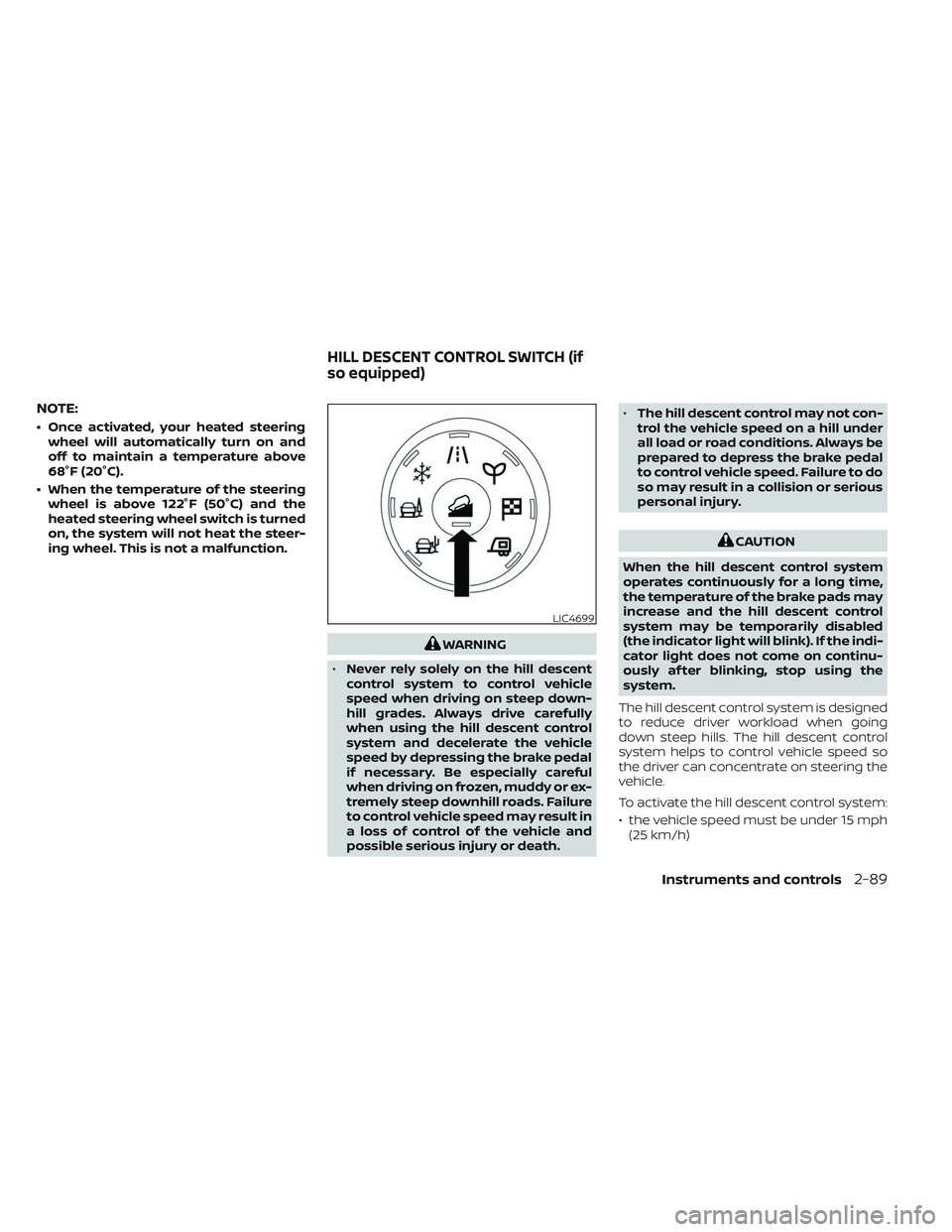
To activate the hill descent control system:
• the vehicle speed must be under 15 mph (25 km/h)
LIC4699
HILL DESCENT CONTROL SWITCH (if
so equipped)
Instruments and controls2-89
Page 209 of 647
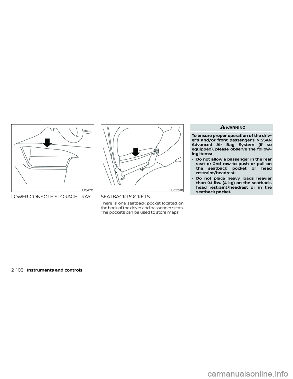
LOWER CONSOLE STORAGE TRAY SEATBACK POCKETS
There is one seatback pocket located on
the back of the driver and passenger seats.
The pockets can be used to store maps.
WARNING
To ensure proper operation of the driv-
er’s and/or front passenger’s NISSAN
Advanced Air Bag System (if so
equipped), please observe the follow-
ing items:
• Do not allow a passenger in the rear
seat or 2nd row to push or pull on
the seatback pocket or head
restraint/headrest.
• Do not place heavy loads heavier
than 9.1 lbs. (4 kg) on the seatback,
head restraint/headrest or in the
seatback pocket.
LIC4711LIC2618
2-102Instruments and controls
Page 216 of 647
LUGGAGE HOOKS
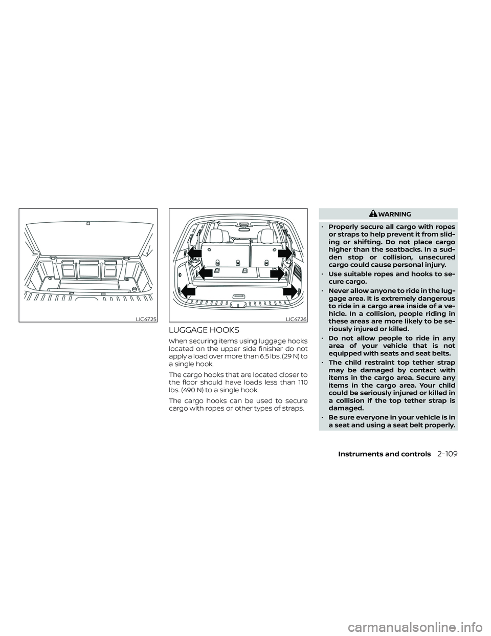
When securing items using luggage hooks
located on the upper side finisher do not
apply a load over more than 6.5 lbs. (29 N) to
a single hook.
The cargo hooks that are located closer to
the floor should have loads less than 110
lbs. (490 N) to a single hook.
The cargo hooks can be used to secure
cargo with ropes or other types of straps.
WARNING
• Properly secure all cargo with ropes
or straps to help prevent it from slid-
ing or shif ting. Do not place cargo
higher than the seatbacks. In a sud-
den stop or collision, unsecured
cargo could cause personal injury.
• Use suitable ropes and hooks to se-
cure cargo.
• Never allow anyone to ride in the lug-
gage area. It is extremely dangerous
to ride in a cargo area inside of a ve-
hicle. In a collision, people riding in
these areas are more likely to be se-
riously injured or killed.
• Do not allow people to ride in any
area of your vehicle that is not
equipped with seats and seat belts.
• The child restraint top tether strap
may be damaged by contact with
items in the cargo area. Secure any
items in the cargo area. Your child
could be seriously injured or killed in
a collision if the top tether strap is
damaged.
• Be sure everyone in your vehicle is in
a seat and using a seat belt properly.
LIC4725LIC4726
Instruments and controls2-109
Page 217 of 647
ROOF RACK (if so equipped)
WARNING
• Always install the crossbars onto the
roof side rails before loading cargo of
any kind. Loading cargo directly onto
the roof side rails or the vehicle’s roof
may cause vehicle damage.
• Roof rack cross bars should be evenly
distributed.
• Do not exceed maximum roof rack
crossbars load capacity and always
distribute the load uniformly. •
Heavy loading of the crossbars has
the potential to affect the vehicle
stability and handling during sudden
or unusual handling maneuvers.
• Properly secure all cargo with ropes
or straps to help prevent it from slid-
ing or shif ting. In a sudden stop or
collision, unsecured cargo could
cause personal injury.
• Drive extra carefully when the vehicle
is loaded at or near the cargo carry-
ing capacity, especially if the signifi-
cant portion of that load is carried on
the crossbars.CAUTION
• Use care when placing or removing
items from the roof rack. If you can-
not comfortably lif t the items onto
the roof rack from the ground, use a
ladder or a stool.
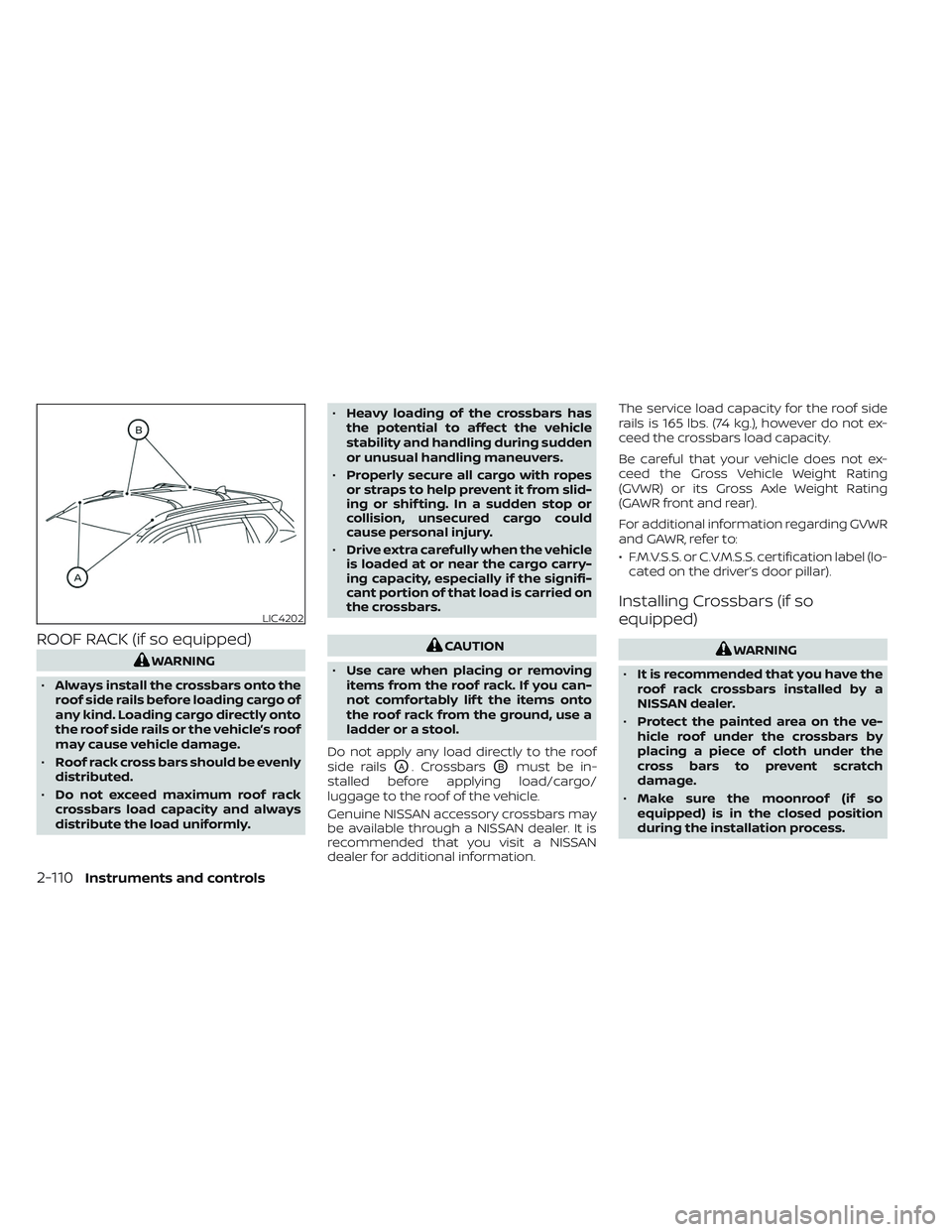
Do not apply any load directly to the roof
side rails
OA. CrossbarsOBmust be in-
stalled before applying load/cargo/
luggage to the roof of the vehicle.
Genuine NISSAN accessory crossbars may
be available through a NISSAN dealer. It is
recommended that you visit a NISSAN
dealer for additional information. The service load capacity for the roof side
rails is 165 lbs. (74 kg.), however do not ex-
ceed the crossbars load capacity.
Be careful that your vehicle does not ex-
ceed the Gross Vehicle Weight Rating
(GVWR) or its Gross Axle Weight Rating
(GAWR front and rear).
For additional information regarding GVWR
and GAWR, refer to:
• F.M.V.S.S. or C.V.M.S.S. certification label (lo-
cated on the driver’s door pillar).
Installing Crossbars (if so
equipped)
WARNING
• It is recommended that you have the
roof rack crossbars installed by a
NISSAN dealer.
• Protect the painted area on the ve-
hicle roof under the crossbars by
placing a piece of cloth under the
cross bars to prevent scratch
damage.
• Make sure the moonroof (if so
equipped) is in the closed position
during the installation process.
LIC4202
2-110Instruments and controls
Page 220 of 647
Depending on the environment or driv-
ing conditions, the auto-reverse func-
tion may be activated if an impact or
load similar to something being caught
in the window occurs.
WARNING
There are some small distances imme-
diately before the closed position
which cannot be detected. Make sure
that all passengers have their hands,
etc., inside the vehicle before closing
the window.
If the vehicle's battery is disconnected, re-
placed, or jump started, the power window
auto-reverse function may not operate
properly. If this occurs, please contact the
dealer to re-initialize the power window
auto-reverse system.
If the control unit detects something
caught in a window equipped with auto-
matic operation, as it is closing, the window
will be immediately lowered.
When power window switch does
not operate
If the power window automatic function
(closing only) does not operate properly,
perform the following procedure to initial-
ize the power window system:
1.
Place the ignition switch in the ON position.
2. Open the window more than half way by operating the power window switch.
3. Pull the power window switch and hold it to close the window, and then hold the
switch more than 3 seconds af ter the
window is closed.
4. Release the power window switch. Op- erate the window by the automatic
function to confirm the initialization is
complete. The power window automati-
cally opens or closes depending on if
the automatic down or up function is
selected.
5. Perform steps 2 through 4 above for other windows.
If the power window function does not op-
erate properly af ter performing the above
procedure have the system checked and
repaired. It is recommended that you visit a
NISSAN dealer for this service.
REAR DOOR SUNSHADE (if so
equipped)
The rear door sunshade is located within
the rear doors at the base of the window.
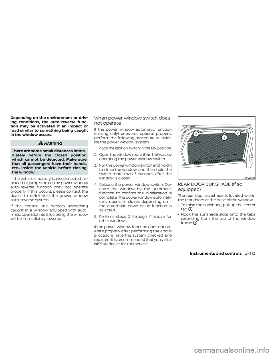
• To raise the sunshade, pull up the center tab
O1.
• Hook the sunshade slots onto the tabs extending from the top of the window
frame
O2.
LIC4169
Instruments and controls2-113
Page 222 of 647
first. When the switch is pushed again, the
moonroof will open fully.)
When the moonroof switch is pushed to
the CLOSE position
O4, the moonroof will
automatically close. When the sunshade
switch is pushed to the CLOSE position
O2,
the sunshade will close. (If the sunshade
starts to close from the position between
full and half open, the sunshade will stop
half. When the switch is pushed again, the
sunshade will close fully. However, if the
moonroof is open or tilted up, the sun-
shade will not close beyond half.)
To stop the sunshade or moonroof during
the operation, push the moonroof switch
to either of the OPEN
O1,O3, CLOSEO2,O4
or UPO5position.
Tilting the moonroof
To tilt up the moonroof, push the moonroof
switch to the UP position
O5. To tilt down
the moonroof, push the switch to the
CLOSE position
O4.
Comfort mode
This is the position used when driving with
the moonroof open. When driving with the
moonroof fully open, wind noise may be
very loud. Use the comfort mode position
when driving.
Auto-reverse function
WARNING
There are some small distances imme-
diately before the closed position
which cannot be detected. Make sure
that all passengers have their hands,
etc., inside the vehicle before closing
the moonroof and sunshade.
The auto-reverse function enables the
moonroof and sunshade to automatically
reverse when something is caught in the
moonroof and sunshade as it is closing.
When the control unit detects an obstacle,
the moonroof and sunshade will open
immediately.
Depending on the environment or driving
conditions, the auto-reverse function may
activate if an impact or load similar to
something being caught in the moonroof
and sunshade occurs.
If the auto-reverse function activates con-
secutively or the battery is discharged, the
moonroof and sunshade may not close
properly. In this case, push and hold the
switch to the CLOSE position
O4to close
the moonroof.
If the moonroof switch does not
operate
If the moonroof and sunshade do not op-
erate properly, perform the following pro-
cedure to initialize the operation system.
1. If the moonroof and sunshade are open, close them fully by repeatedly pushing
the moonroof switch to the CLOSE
O2
andO4position.
2. Push and hold the moonroof switch to the CLOSE
O4position for 10 seconds.
3. Af ter the moonroof and sunshade move slightly to the closed position and
then move back a little, release the
moonroof switch.
4. Push and hold the moonroof switch to the CLOSE
O4position, and the glass
and shade will move.
5. Release the moonroof switch. Then the moonroof and sunshade will fully open
and then fully close.
6. Check if the moonroof switch operates normally.
Instruments and controls2-115