automatic engine start NISSAN PATHFINDER 2022 Owner´s Manual
[x] Cancel search | Manufacturer: NISSAN, Model Year: 2022, Model line: PATHFINDER, Model: NISSAN PATHFINDER 2022Pages: 647, PDF Size: 8.48 MB
Page 501 of 647
•When the fan speed control is in any
position other than “OFF,” (0) while the
air flow control is in the front defogger
position.
• When the front defroster switch is on.
• When the rear window defroster switch
is on.
• When the temperature inside the ve-
hicle is lower than approximately 20°C
(68°F), unless the Air Conditioning ECO
customize option is selected, and the
ECO driving mode is on.
• When the temperature inside the ve-
hicle is higher than approximately 30°C
(86°F), unless the Air Conditioning ECO
customize option is selected, and the
ECO driving mode is on. (When the air
conditioner is off, the Idling Stop Sys-
tem will operate.)
• When the fan speed of the air condi-
tioner is set to the maximum speed,
unless the Air Conditioning ECO cus-
tomize option is selected, and the ECO
driving mode is on.
• When the Idling Stop OFF switch is
turned on.
• When the power consumption is large.
• When the vehicle is traveling at alti-
tudes higher than 6,562 f t (2,000 m). •
When the accelerator pedal is
depressed.
• When the shif t lever is in the R (Reverse)
position.
• When the brake pedal is not firmly
depressed.
• When stopping the vehicle on steep
sloping roads.
NOTE:
The engine will not restart even if the
brake pedal is released while the Idling
Stop System is activated under the fol-
lowing conditions: (The engine may re-
start by the other engine restart condi-
tions.)
• When the shif t position is in the P (Park)
position.
NOTE:
It may take some time until the Idling
Stop System activates under the follow-
ing conditions:
• When the battery is discharged.
• When the outside temperature is low or
high.
•
When the battery is replaced or the bat-
tery terminal is disconnected for ex-
tended periods and then reconnected.
NOTE:
When the Idling Stop System indicator
light illuminates, the engine starts run-
ning automatically under at least one of
the following conditions:
• The brake pedal is released with the
shif t lever in the D (Drive) or N (Neutral)
position.
• The shif t position is placed in the D
(Drive) or R (Reverse) position from the
N (Neutral) or P (Park) position.
• The driver’s seat belt is unfastened, or
the driver’s door is open.
• The battery voltage becomes low (due
to electrical load from other vehicle
systems like headlights, heaters, etc.,
or auxiliary devices connected to the
12 volt socket inside the vehicle).
• The vehicle speed is above about 1 mph
(2 km/h).
• When the rear window defroster is
operated.
• When the temperature inside the ve-
hicle is lower than approximately 68°F
(20°C), unless the Air Conditioning ECO
customize option is selected, and the
ECO driving mode is on.
5-190Starting and driving
Page 502 of 647
•When the temperature inside the ve-
hicle is higher than approximately 86°F
(30°C), unless the Air Conditioning ECO
customize option is selected, and the
ECO driving mode is on. (When the air
conditioner is off, the Idling Stop Sys-
tem will operate.)
• When the front defroster is turned on.
• When more than 3 minutes have
elapsed since the Idling Stop System
was active.
• When the accelerator pedal is
depressed.
• When the steering wheel is operated.
(The steering wheel operation may be-
come heavy, but this is not a
malfunction.)
• When the battery capacity is low.
• When the power consumption is high.
• When the shif t lever is placed in the R
(Reverse) position.
• When the Idling Stop OFF switch is
pushed.
• When the negative pressure of the
brake system is not sufficiently applied
by depressing the brake pedal several
times.NOTE:
The following condition will prevent the
Idling Stop System from automatically
restarting the engine. Starting the en-
gine with the ignition switch operation is
then necessary:
• The hood is open.
Use this system while waiting at a stop
light, etc. When the vehicle is stopped for
long periods of time, turn off the engine.
When the engine is stopped by the Idling
Stop System, heating, cooling and dehu-
midif ying functions will be deactivated. To
avoid the air conditioning functions from
being deactivated, turn off the Idling Stop
System by pushing the Idling Stop OFF
switch.
RETROGRADE MOVEMENT
CONTROL FUNCTION
This system is designed to reduce the ret-
rograde movement that occurs while the
driver’s foot changes from depressing the
brake pedal to the accelerator pedal when
moving the vehicle while the Idling Stop
System is active on a hilly road.
IDLING STOP SYSTEM DISPLAY
The status of the Idling Stop System can be
checked in the vehicle information display.
Starting and driving5-191
Page 503 of 647
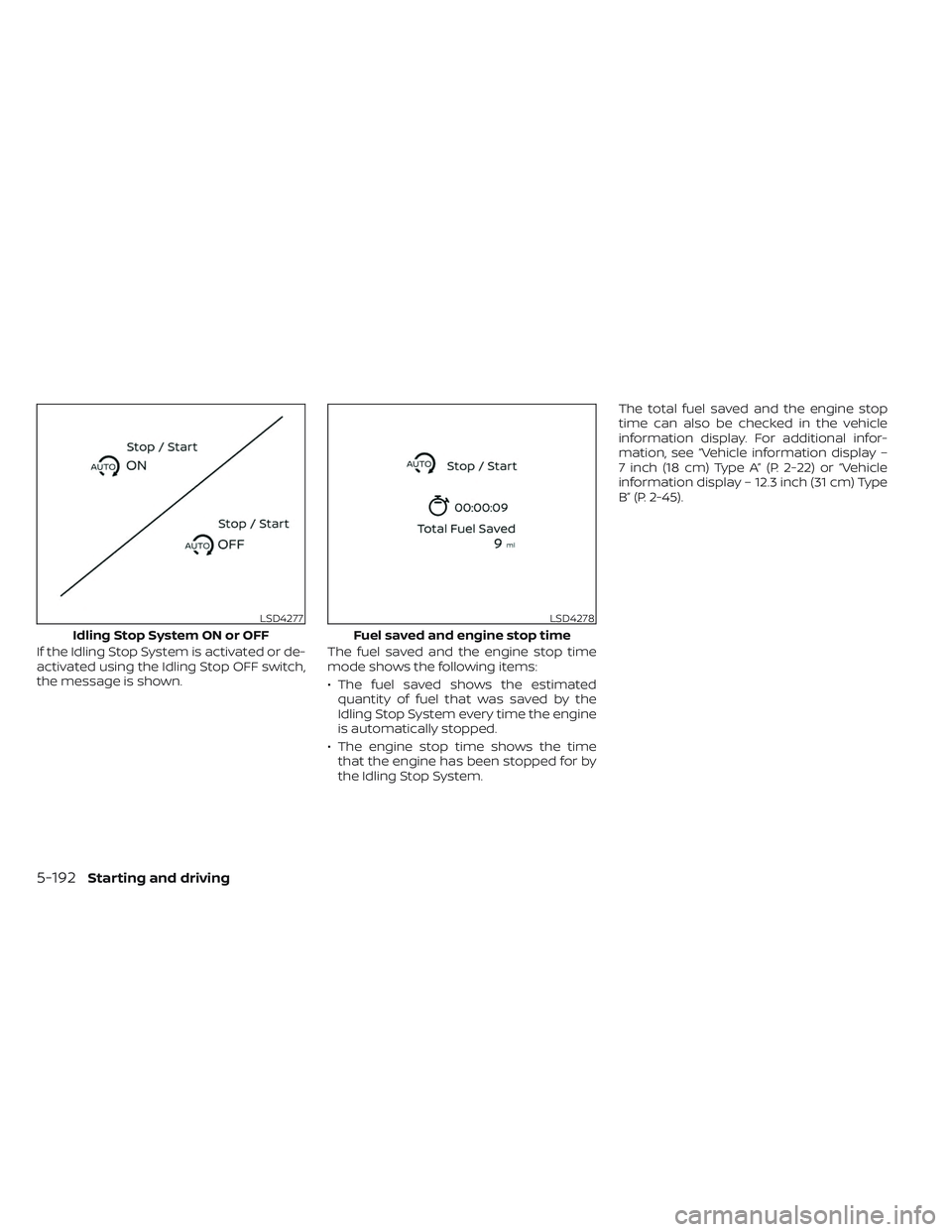
If the Idling Stop System is activated or de-
activated using the Idling Stop OFF switch,
the message is shown.The fuel saved and the engine stop time
mode shows the following items:
• The fuel saved shows the estimated
quantity of fuel that was saved by the
Idling Stop System every time the engine
is automatically stopped.
• The engine stop time shows the time that the engine has been stopped for by
the Idling Stop System. The total fuel saved and the engine stop
time can also be checked in the vehicle
information display. For additional infor-
mation, see “Vehicle information display –
7 inch (18 cm) Type A” (P. 2-22) or “Vehicle
information display – 12.3 inch (31 cm) Type
B” (P. 2-45).
LSD4277
Idling Stop System ON or OFF
LSD4278
Fuel saved and engine stop time
5-192Starting and driving
Page 504 of 647
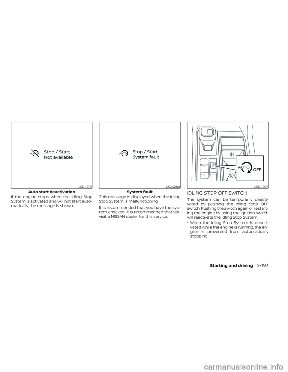
If the engine stops when the Idling Stop
System is activated and will not start auto-
matically, the message is shown.This message is displayed when the Idling
Stop System is malfunctioning.
It is recommended that you have the sys-
tem checked. It is recommended that you
visit a NISSAN dealer for this service.IDLING STOP OFF SWITCH
The system can be temporarily deacti-
vated by pushing the Idling Stop OFF
switch. Pushing the switch again or restart-
ing the engine by using the ignition switch
will reactivate the Idling Stop System.
• When the Idling Stop System is deacti-
vated while the engine is running, the en-
gine is prevented from automatically
stopping.
LSD4279
Auto start deactivation
LSD4280
System fault
LSD4207
Starting and driving5-193
Page 519 of 647
•Whenever working on or near a bat-
tery, always wear suitable eye pro-
tectors (for example, goggles or in-
dustrial safety spectacles) and
remove rings, metal bands, or any
other jewelry. Do not lean over the
battery when jump starting.
• Do not attempt to jump start a frozen
battery. It could explode and cause
serious injury.
• Your vehicle has an automatic engine
cooling fan. It could come on at any
time. Keep hands and other objects
away from it.
WARNING
Always follow the instructions below.
Failure to do so could result in damage
to the charging system and cause per-
sonal injury.
1. If the booster battery is in another ve- hicle, position the two vehicles to bring
their batteries near each other.
Do not allow the two vehicles to touch. 2. Apply the parking brake. Push the park
button to shif t to the P (Park) position.
Switch off all unnecessary electrical sys-
tems (lights, heater, air conditioner, etc.).
3. Place the ignition switch to the LOCK or OFF position.
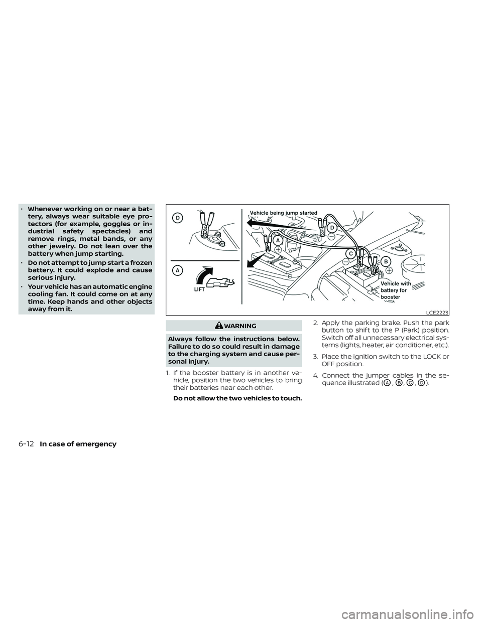
4. Connect the jumper cables in the se- quence illustrated (
OA,OB,OC,OD).
LCE2223
6-12In case of emergency
Page 520 of 647
CAUTION
• Always connect positive (+) to posi-
tive (+) and negative (−) to body
ground (for example, strut mounting
bolt, engine lif t bracket, etc.) — not to
the battery.
• Make sure the jumper cables do not
touch moving parts in the engine
compartment and that the cable
clamps do not contact any other
metal.
5. Start the engine of the booster vehicle and let it run for a few minutes.
6. Keep the engine speed of the booster vehicle at about 2,000 rpm and start the
engine of the vehicle being jump
started.
CAUTION
Do not keep the starter motor engaged
for more than 10 seconds. If the engine
does not start right away, place the ig-
nition switch in the OFF position and
wait 3 to 4 seconds before trying again.
7. Af ter starting the engine, carefully dis- connect the negative cable and then the
positive cable.
CAUTION
Automatic transmission models can-
not be push-started. Attempting to do
so may cause transmission damage.WARNING
• Do not continue to drive if your ve-
hicle overheats. Doing so could cause
engine damage or a vehicle fire.
• To avoid the danger of being scalded,
never remove the radiator or coolant
reservoir cap while the engine is still
hot. When the radiator or coolant res-
ervoir cap is removed, pressurized
hot water will spurt out, possibly
causing serious injury.
• Do not open the hood if steam is
coming out.
If your vehicle is overheating (indicated by
an extremely high temperature gauge
reading and the Low Oil Pressure: See
Owner’s Manual warning message ap-
pears in the vehicle information display), or
if you feel a lack of engine power, detect
abnormal noise, etc. take the following
steps:
1. Move the vehicle safely off the road, ap- ply the parking brake.
2. Push the park button to shif t to the P (Park) position.
Do not stop the engine.
PUSH STARTING IF YOUR VEHICLE OVERHEATS
In case of emergency6-13
Page 534 of 647
8 Do-it-yourself
Maintenance precautions.......................8-2
Engine compartment check locations ...........8-4
Engine cooling system ..........................8-5
Checking engine coolant level ................8-6
Changing engine coolant ....................8-6
Engine oil .......................................8-7
Checking engine oil level .....................8-7
Changing engine oil and oil filter ..............8-7
Automatic Transmission Fluid (ATF) ..............8-11
Brake fluid ...................................... 8-12
Windshield-washer fluid ........................8-12
Windshield-washer fluid reservoir ...........8-12
Battery......................................... 8-14
Jump starting ............................... 8-15
Variable voltage control system
(if so equipped) ................................. 8-16
Drive belt ....................................... 8-16
Spark plugs .................................... 8-17
Replacing spark plugs ....................... 8-17
Air cleaner ..................................... 8-18In-cabin microfilter
.......................... 8-18
Windshield wiper blades ........................8-19
Cleaning .................................... 8-19
Replacing ................................... 8-19
Brakes ......................................... 8-21
Fuses .......................................... 8-21
Engine compartment .......................8-22
Passenger compartment ...................8-23
Battery replacement ........................... 8-25
NISSAN Intelligent Key® ......................8-25
Lights .......................................... 8-27
Headlights .................................. 8-27
Fog lights (if so equipped) ...................8-27
Exterior and interior lights ...................8-27
Wheels and tires ............................... 8-29
Tire pressure ................................ 8-29
Tire labeling ................................. 8-34
Types of tires ................................
8-36
Tir
e chains .................................. 8-37
Changing wheels and tires ..................8-38
Page 544 of 647
CAUTION
Be sure to remove any old gasket ma-
terial remaining on the sealing surface
of the engine. Failure to do so could
lead to an oil leak and engine damage.
• The dipstick must be inserted in
place to prevent oil spillage from the
dipstick hole when filling the engine
with oil.
6. Coat the gasket on the new filter with clean engine oil.
7. Screw in the oil filter clockwise until a slight resistance is felt, then tighten addi-
tionally more than 2/3 turn.
Oil filter tightening torque: 15.0 to 21.0 N·m (11 to 15 f t-lb)
8. Clean and re-install the drain plug with a new washer. Securely tighten the drain
plug with a wrench. Do not use exces-
sive force.
Drain plug tightening torque: 29.4 to 39.2 N·m (22 to 29 f t-lb)
9. Refill the engine with the recommended oil through the oil filler opening, and in-
stall the oil filler cap securely. For additional information about drain and
refill capacity, see “Recommended fluids/
lubricants and capacities” (P. 10-2). The
drain and refill capacity depends on the oil
temperature and drain time. Use these
specifications for reference only. Always
use the dipstick to determine the proper
amount of oil in the engine.
10. Start the engine and check for leakage
around the drain plug and the oil filter.
Correct as required. Turn the engine off
and wait more than 15 minutes. Check
the oil level with the dipstick. Add en-
gine oil if necessary.
Af ter the operation
1. Reinstall engine protectors in reverse or-der of removal.
2. Lower the vehicle carefully to the ground.
3. Reset oil and oil filter maintenance re- minder. For additional information, see
“Vehicle information display 7 inch (18
cm) Type A” (P. 2-22) or “Vehicle informa-
tion display 12.3 inch (31 cm) Type B”
(P. 2-45).
• Dispose of waste oil and filter properly.
• Check your local regulations. When checking or replacement is required,
it is recommended that you visit a NISSAN
dealer for this service.
CAUTION
• NISSAN recommends using Genuine
NISSAN Matic R ATF. Do not mix with
other fluids.
• Do not use CVT fluid or manual trans-
mission fluid in this transmission.
Damage caused by the use of fluids
other than as recommended is not
covered under NISSAN’s New Vehicle
Limited Warranty outlined in your
Warranty Information Booklet.
• Using fluids that are not equivalent
to Genuine NISSAN Matic R ATF may
also damage the transmission. Dam-
age caused by the use of fluids other
than as recommended is not covered
under NISSAN’s New Vehicle Limited
Warranty outlined in your Warranty
Information Booklet.
The specified automatic transmission fluid
is also described on caution labels located
in the engine compartment.
AUTOMATIC TRANSMISSION FLUID
(ATF)
Do-it-yourself8-11
Page 636 of 647
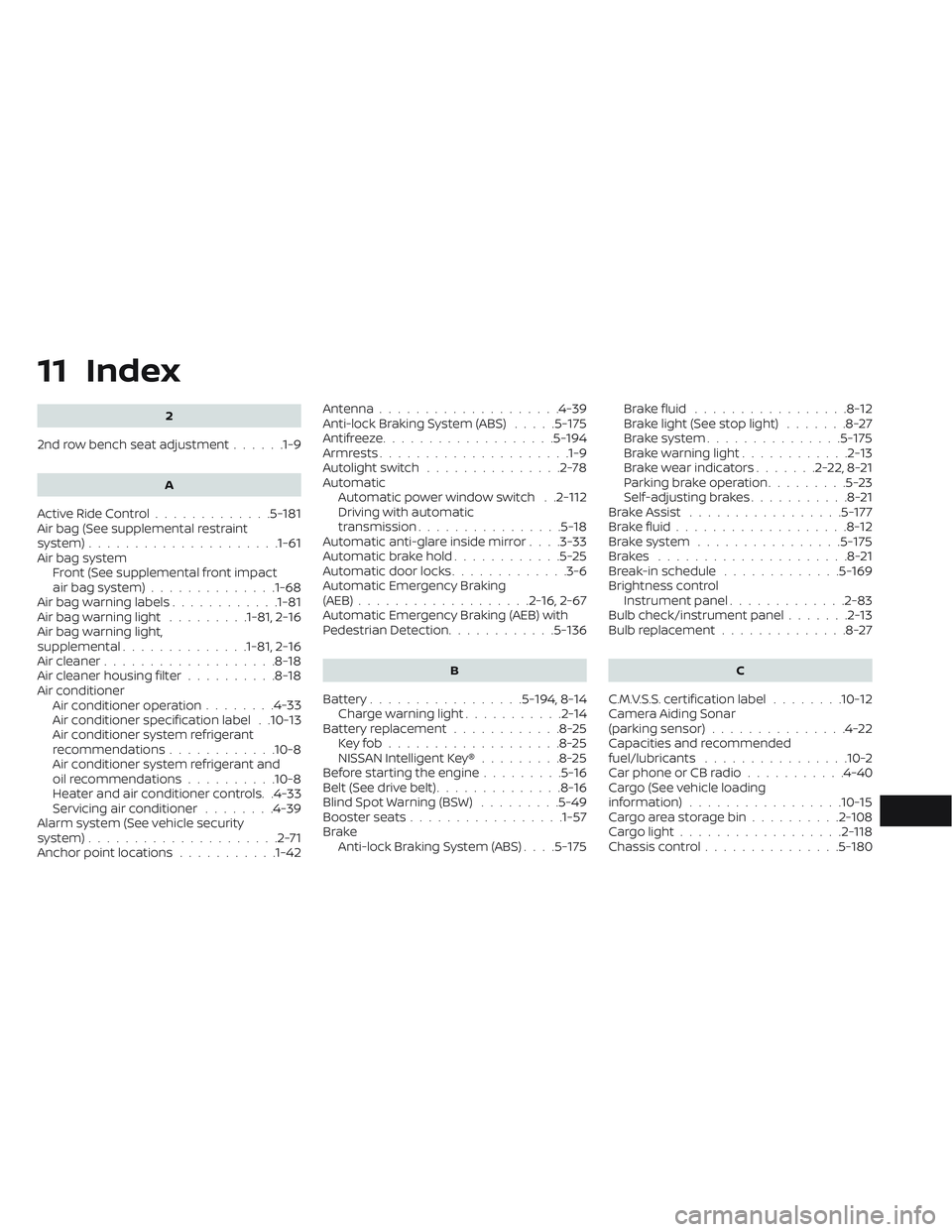
11 Index
2
2nd row bench seat adjustment......1-9
A
Active Ride Control.............5-181Air bag (See supplemental restraint
system).....................1-61Air bag system
Front (See supplemental front impact
air bag system)
..............1-68Air bag warning labels............1-81Air bag warning light.........1-81, 2-16Air bag warning light,
supplemental..............1-81, 2-16Air cleaner...................8-18Air cleaner housing filter..........8-18Air conditionerAir conditioner operation........4-33Air conditioner specification label. .10-13Air conditioner system refrigerant
recommendations............10-8Air conditioner system refrigerant and
oil recommendations..........10-8Heater and air conditioner controls. .4-33Servicing air conditioner........4-39Alarm system (See vehicle security
system).....................2-71Anchor point locations...........1-42
Antenna................... .4-39Anti-lock Braking System (ABS).....5-175Antifreeze...................5-194Armrests.................... .1-9Autolight switch...............2-78Automatic
Automatic power window switch. .2-112Driving with automatic
transmission................5-18Automatic anti-glare inside mirror. . . .3-33Automatic brake hold............5-25Automatic door locks.............3-6Automatic Emergency Braking
(AEB)...................2-16, 2-67Automatic Emergency Braking (AEB) with
Pedestrian Detection............5-136
B
Battery.................5-194, 8-14Charge warning light...........2-14Battery replacement............8-25Key fob...................8-25NISSAN Intelligent Key®.........8-25Before starting the engine.........5-16Belt (See drive belt)..............8-16Blind Spot Warning (BSW).........5-49Booster seats.................1-57Brake
Anti-lock Braking System (ABS). . . .5-175
Brake fluid.................8-12Brake light (See stop light).......8-27Brake system...............5-175Brake warning light............2-13Brake wear indicators.......2-22,8-21Parking brake operation.........5-23Self-adjusting brakes...........8-21Brake Assist.................5-177Brake fluid...................8-12Brake system................5-175Brakes.....................8-21Break-in schedule.............5-169Brightness controlInstrument panel.............2-83Bulb check/instrument panel.......2-13Bulb replacement..............8-27
C
C.M.V.S.S. certification label........10-12Camera Aiding Sonar
(parking sensor)...............4-22Capacities and recommended
fuel/lubricants................10-2Car phone or CB radio...........4-40Cargo (See vehicle loading
information)................ .10-15Cargo area storage bin..........2-108Cargo light..................2-118Chassis control...............5-180
Page 637 of 647
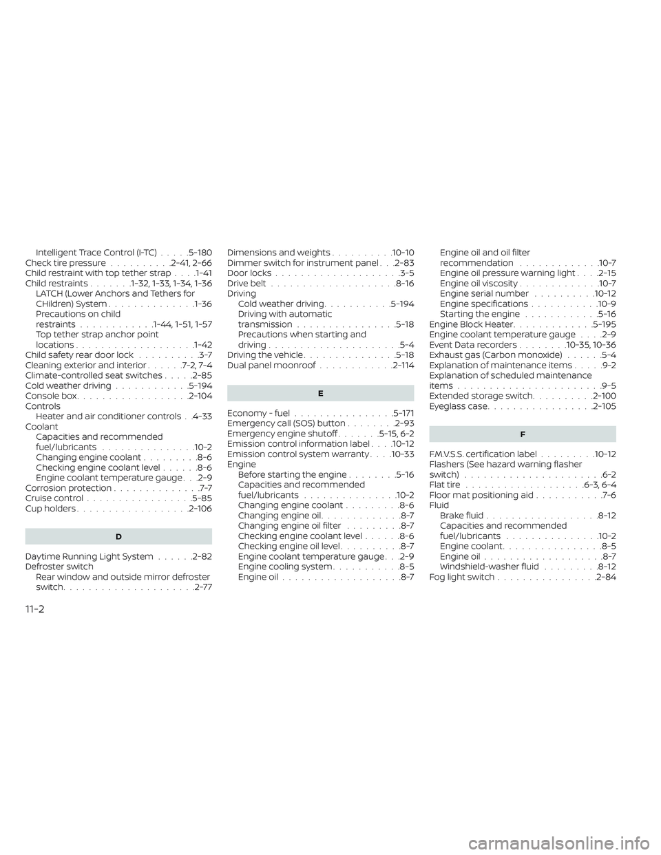
Intelligent Trace Control (I-TC).....5-180Check tire pressure..........2-41, 2-66Child restraint with top tether strap. . . .1-41Child restraints.......1-32, 1-33, 1-34, 1-36LATCH (Lower Anchors and Tethers for
CHildren) System..............1-36Precautions on child
restraints............1-44, 1-51, 1-57Top tether strap anchor point
locations...................1-42Child safety rear door lock..........3-7Cleaning exterior and interior......7-2,7-4Climate-controlled seat switches.....2-85Cold weather driving............5-194Console box..................2-104Controls
Heater and air conditioner controls. .4-33CoolantCapacities and recommended
fuel/lubricants
...............10-2Changing engine coolant.........8-6Checking engine coolant level......8-6Engine coolant temperature gauge. . .2-9Corrosion protection..............7-7Cruise control................ .5-85Cup holders..................2-106
D
Daytime Running Light System......2-82Defroster switch
Rear window and outside mirror defroster
switch
.....................2-77
Dimensions and weights..........10-10Dimmer switch for instrument panel. . .2-83Door locks................... .3-5Drive belt....................8-16Driving
Cold weather driving...........5-194Driving with automatic
transmission................5-18Precautions when starting and
driving.................... .5-4Driving the vehicle...............5-18Dual panel moonroof............2-114
E
Economy - fuel................5-171Emergency call (SOS) button........2-93Emergency engine shutoff.......5-15,6-2Emission control information label. . . .10-12Emission control system warranty. . . .10-33Engine
Before starting the engine........5-16Capacities and recommended
fuel/lubricants...............10-2Changing engine coolant.........8-6Changing engine oil.............8-7Changing engine oil filter.........8-7Checking engine coolant level......8-6Checking engine oil level..........8-7Engine coolant temperature gauge. . .2-9Engine cooling system...........8-5Engine oil...................8-7
Engine oil and oil filter
recommendation.............10-7Engine oil pressure warning light. . . .2-15Engine oil viscosity.............10-7Engine serial number..........10-12Engine specifications...........10-9Starting the engine............5-16Engine Block Heater.............5-195Engine coolant temperature gauge. . . .2-9Event Data recorders........10-35, 10-36Exhaust gas (Carbon monoxide)......5-4Explanation of maintenance items.....9-2Explanation of scheduled maintenance
items...................... .9-5Extended storage switch..........2-100Eyeglass case.................2-105
F
F.M.V.S.S. certification label.........10-12Flashers (See hazard warning flasher
switch)......................6-2Flat tire...................6-3, 6-4Floor mat positioning aid...........7-6Fluid
Brake fluid..................8-12Capacities and recommended
fuel/lubricants...............10-2Engine coolant................8-5Engine oil...................8-7Windshield-washer fluid.........8-12Fog light switch................2-84
11-2