oil temperature NISSAN PATHFINDER 2022 Owner´s Manual
[x] Cancel search | Manufacturer: NISSAN, Model Year: 2022, Model line: PATHFINDER, Model: NISSAN PATHFINDER 2022Pages: 647, PDF Size: 8.48 MB
Page 108 of 647
2 Instruments and controls
Instrument panel................................2-4
Meters and gauges .............................2-6
Speedometer and odometer .................2-6
Tachometer ..................................2-8
Engine coolant temperature gauge ..........2-9
Fuel gauge .................................. 2-10
Distance To Empty (DTE) ....................2-10
Warning lights, indicator lights and audible
reminders ...................................... 2-12
Checking lights .............................. 2-13
Warning/Indicator lights (red) ...............2-13
Warning/Indicator lights (yellow) ............2-16
Warning/Indicator lights (other) .............2-21
Audible reminders ........................... 2-22
Vehicle information display 7 inch (18 cm)
Type A (if so equipped) ......................... 2-22
How to use the vehicle information
display ...................................... 2-23
Startup display .............................. 2-23
Trip computer ............................... 2-24
Oil control system (if so equipped) ...........2-27
Settings ..................................... 2-28
Vehicle information display warnings
and indicators ............................... 2-37
Vehicle information display 12.3 inch (31 cm)
Type B (if so equipped) ......................... 2-45How to use the vehicle information
display
...................................... 2-46
Startup display .............................. 2-46
Trip computer ...............................2-47
Changing the meter screen view ............2-50
Oil control system (if so equipped) ...........2-51
Settings ..................................... 2-52
Vehicle information display warnings
and indicators ............................... 2-61
Security systems ............................... 2-71
Vehicle security system .....................2-71
NISSAN Vehicle Immobilizer System .........2-72
Wiper and washer switch .......................2-73
Switch operation ............................ 2-73
Rain-sensing auto wiper system
(if so equipped) .............................. 2-75
Rear switch operation .......................2-76
R
ear window and outside mirror
(if so equipped) defroster switch ...............2-77
Headlight and turn signal switch ...............2-78
Headlight control switch ....................2-78
LED Daytime Running Lights (DRL)
system ...................................... 2-82
Instrument brightness control ..............2-83
Turn signal switch ........................... 2-83
Fog light switch (if so equipped) .............2-84
Page 146 of 647
Low Fuel
This warning appears when the fuel level in
the fuel tank is getting low. Refuel as soon
as it is convenient, preferably before the
fuel gauge reaches 0 (Empty).There will be
a small reserve of fuel in the tank when
the fuel gauge needle reaches 0 (Empty).
Low Oil Pressure: See
Owner’s Manual
This warning appears in the message area
of the vehicle information display if low oil
pressure is detected. This gauge is not de-
signed to indicate low oil level. The low oil
pressure warning is not designed to indi-
cate a low oil level. Use the dipstick to
check the oil level. For additional informa-
tion, see “Engine oil” (P. 8-7).
Low Outside Temperature
This warning appears if the outside tem-
perature is below 37°F (3°C). The tempera-
ture can be changed to display in Celsius or
Fahrenheit. For additional information, see
“Driver Assistance” (P. 2-28).
Low Washer Fluid
This warning appears when the windshield-
washer fluid is at a low level. Add windshield-
washer fluid as necessary. For additional
information, see “Windshield-washer fluid”
(P. 8-12).
Parking Sensor Error: See Owner’s
Manual
This warning appears when there is an er-
ror with the system. For additional informa-
tion, see “Front and rear sonar system”
(P. 5-183).
Power will turn off to save the battery
This message appears in the vehicle infor-
mation display af ter a period of time if the
ignition switch is in the ON position and if
the vehicle is in P (Park). For additional infor-
mation, see “Push-button ignition switch
positions” (P. 5-14).
Power turned off to save the battery
This message appears af ter the ignition
switch is automatically turned off. For addi-
tional information, see “Push-button igni-
tion switch positions” (P. 5-14).
Press Brake Pedal
This warning appears in the following situ-
ations:
• The driver tries to release the electronic parking brake manually without depress-
ing the brake pedal.
• The vehicle is stopped on a steep hill and there is a possibility of moving backward,
even if the electronic parking brake is
applied.
• This warning appears if the vehicle moves while the automatic brake hold is
activated.
Press brake to operate
switch
This warning appears if the automatic
brake hold switch is pushed without de-
pressing the brake pedal while the auto-
matic brake hold function is activated. De-
press the brake pedal and push the switch
to deactivate the automatic brake hold
function.
For additional information, see “Automatic
brake hold” (P. 5-25).
Instruments and controls2-39
Page 206 of 647
WARNING
• Never put metallic materials be-
tween the wireless charger and a
smartphone.
• Those who use a pacemaker or other
medical equipment should contact
the electric medical equipment
manufacturer for the possible influ-
ences before use.
• Never put cloth over the smartphone
during charging process.
• Never charge a smartphone when it
is wet.
• Never put metallic materials or small
goods such as a cigarette lighter, In-
telligent Key or memory drive.
CAUTION
• Do not put an RFID/NFC/credit card
between the wireless charger and a
smartphone. This could cause data
corruption in the card.
• Do not use the wireless charger with
dust accumulated or dirt on the pad.
• Do not hit the surface of the wireless
charger. •
Do not spill liquid (water, drinks, etc.)
on the charging pad.
• Do not use grease, oil or alcohol for
cleaning charging pad.
WIRELESS CHARGER INDICATOR
The indicator(1)willil luminate in orange
when the charging process is started.
When the charging has completed, the in-
dicator illuminates in green.
If a malfunction occurs or the charging
process has stopped, the indicator will
blink in orange for 8 seconds then turn off.
WIRELESS CHARGER OPERATION
To use the wireless charger, it is necessary
to seat the smartphone well within the
charging pad. To maximize charging per-
formance, ensure the smartphone is fully
seated on the center of the charging pad
over the "Qi" logo
OA. Because the location
of the power receiver may vary depending
on the smartphone, you will need to try and
find the area that suits your smartphone.
Because some smartphone cases or ac-
cessories may adversely affect charging,
remove them before wireless charging.
Turn off the vibration function of the smart-
phone before wireless charging.
NOTE:
• Only a Qi compatible smartphone can
be used.
• The smartphone may be warmed dur-
ing charging process and the charging
may stop by the protection function of
the wireless charger. This is not a mal-
function. If this occurs, restart charging
af ter the smartphone cooled down.
The indicator will blink in orange then
turn off.
• The wireless charging process may be
stopped by the status of the smart-
phone (battery temperature, etc.).
• If a radio noise interference occurs dur-
ing charging process, put the smart-
phone onto the center (“Qi” logo) posi-
tion of the wireless charger.
• The wireless charging process will stop
during process of searching the Intelli-
gent Key.
• The wireless charging process will not
be started when a USB (Universal Serial
Bus) cable is connected to the smart-
phone. The indicator may illuminate in
orange or blink if the smartphone is
put on the wireless charger with a USB
cable connected. However, charging is
not performed.
Instruments and controls2-99
Page 481 of 647
Follow these easy-to-use Fuel Efficient
Driving Tips to help you achieve the most
fuel economy from your vehicle.
1.Use Smooth Accelerator and Brake
Pedal Application
• Avoid rapid starts and stops.
• Use smooth, gentle accelerator and brake application whenever possible.
• Maintain constant speed while com- muting and coast whenever possible.
2. Maintain Constant Speed
• Look ahead to try and anticipate and minimize stops.
• Synchronizing your speed with traffic lights allows you to reduce your num-
ber of stops.
• Maintaining a steady speed can mini- mize red light stops and improve fuel
efficiency.
3. Use Air Conditioning (A/C) at Higher
Vehicle Speeds
• Below 40 mph (64 km/h), it is more efficient to open windows to cool the
vehicle due to reduced engine load.
• Above 40 mph (64 km/h), it is more efficient to use A/C to cool the vehicle
due to increased aerodynamic drag. • Recirculating the cool air in the cabin
when the A/C is on reduces cooling
load.
4. Drive at Economical Speeds and
Distances
• Observing the speed limit and not ex- ceeding 60 mph (97 km/h) (where le-
gally allowed) can improve fuel effi-
ciency due to reduced aerodynamic
drag.
• Maintaining a safe following distance behind other vehicles reduces unnec-
essary braking.
• Safely monitoring traffic to anticipate changes in speed permits reduced
braking and smooth acceleration
changes.
• Select a gear range suitable to road conditions.
5. Use Cruise Control
• Using cruise control during highway driving helps maintain a steady speed.
• Cruise control is particularly effective in providing fuel savings when driving
on flat terrains.
6. Plan for the Shortest Route
• Utilize a map or navigation system to determine the best route to save time. 7.
Avoid Idling
• Shutting off your engine when safe for stops exceeding 30–60 seconds saves
fuel and reduces emissions.
8. Buy an Automated Pass for Toll Roads
• Automated passes permit drivers to use special lanes to maintain cruising
speed through the toll and avoid stop-
ping and starting.
9. Winter Warm Up
• Limit idling time to minimize impact to fuel economy.
• Vehicles typically need no more than 30 seconds of idling at start-up to ef-
fectively circulate the engine oil before
driving.
• Your vehicle will reach its ideal operat- ing temperature more quickly while
driving versus idling.
10. Keeping your Vehicle Cool
• Park your vehicle in a covered parking area or in the shade whenever
possible.
• When entering a hot vehicle, opening the windows will help to reduce the
inside temperature faster, resulting in
reduced demand on your A/C system.
FUEL EFFICIENT DRIVING TIPS
5-170Starting and driving
Page 482 of 647
• Keep your engine tuned up.
• Follow the recommended scheduledmaintenance.
• Keep the tires inflated to the correct pres- sure. Low tire pressure increases tire
wear and lowers fuel economy.
• Keep the wheels in correct alignment. Im- proper alignment increases tire wear and
lowers fuel economy.
•
Use the recommended viscosity engine
oil. For additional information, see “Engine
oil and oil filter recommendations” (P. 8-10).
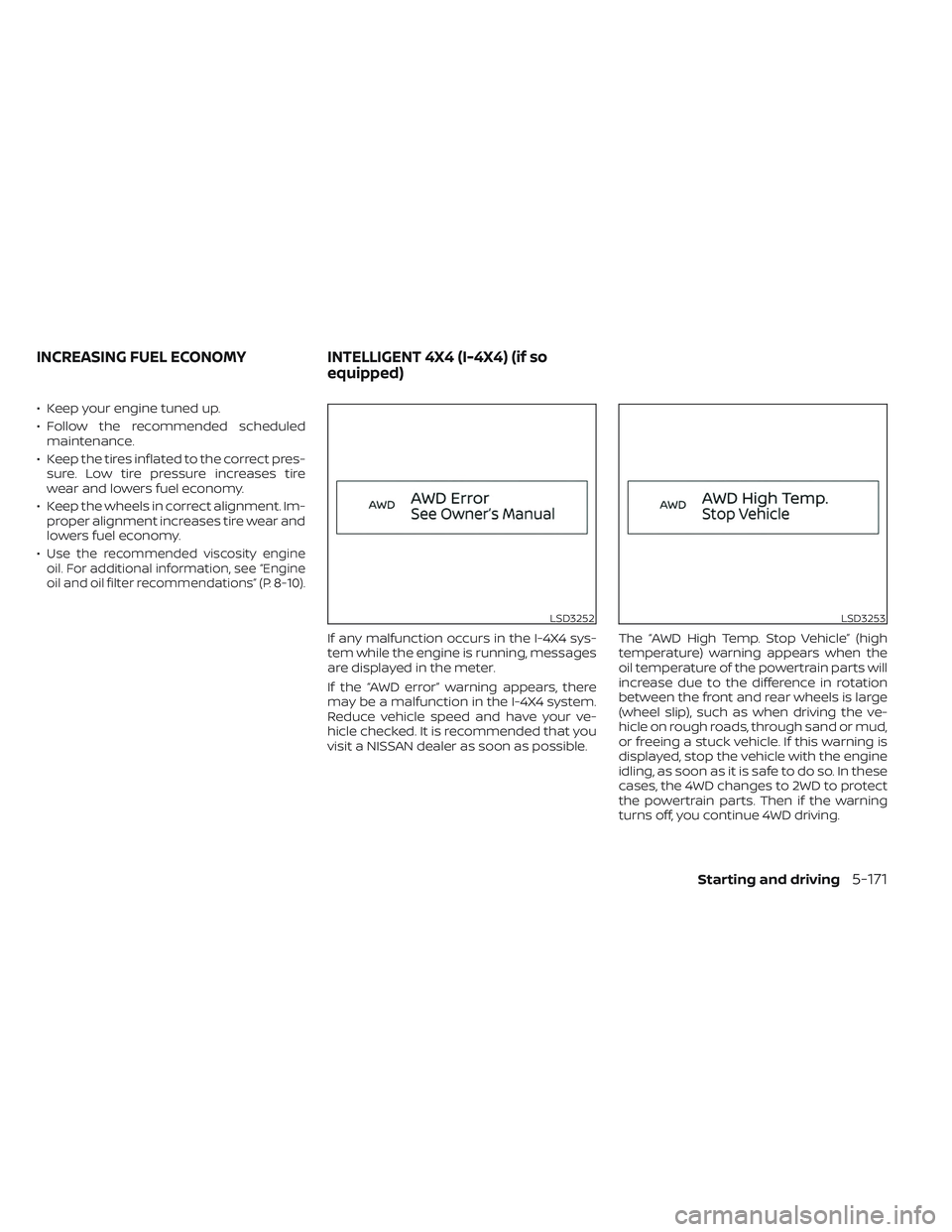
If any malfunction occurs in the I-4X4 sys-
tem while the engine is running, messages
are displayed in the meter.
If the “AWD error” warning appears, there
may be a malfunction in the I-4X4 system.
Reduce vehicle speed and have your ve-
hicle checked. It is recommended that you
visit a NISSAN dealer as soon as possible. The “AWD High Temp. Stop Vehicle” (high
temperature) warning appears when the
oil temperature of the powertrain parts will
increase due to the difference in rotation
between the front and rear wheels is large
(wheel slip), such as when driving the ve-
hicle on rough roads, through sand or mud,
or freeing a stuck vehicle. If this warning is
displayed, stop the vehicle with the engine
idling, as soon as it is safe to do so. In these
cases, the 4WD changes to 2WD to protect
the powertrain parts. Then if the warning
turns off, you continue 4WD driving.
LSD3252LSD3253
INCREASING FUEL ECONOMY
INTELLIGENT 4X4 (I-4X4) (if so
equipped)
Starting and driving5-171
Page 520 of 647
CAUTION
• Always connect positive (+) to posi-
tive (+) and negative (−) to body
ground (for example, strut mounting
bolt, engine lif t bracket, etc.) — not to
the battery.
• Make sure the jumper cables do not
touch moving parts in the engine
compartment and that the cable
clamps do not contact any other
metal.
5. Start the engine of the booster vehicle and let it run for a few minutes.
6. Keep the engine speed of the booster vehicle at about 2,000 rpm and start the
engine of the vehicle being jump
started.
CAUTION
Do not keep the starter motor engaged
for more than 10 seconds. If the engine
does not start right away, place the ig-
nition switch in the OFF position and
wait 3 to 4 seconds before trying again.
7. Af ter starting the engine, carefully dis- connect the negative cable and then the
positive cable.
CAUTION
Automatic transmission models can-
not be push-started. Attempting to do
so may cause transmission damage.WARNING
• Do not continue to drive if your ve-
hicle overheats. Doing so could cause
engine damage or a vehicle fire.
• To avoid the danger of being scalded,
never remove the radiator or coolant
reservoir cap while the engine is still
hot. When the radiator or coolant res-
ervoir cap is removed, pressurized
hot water will spurt out, possibly
causing serious injury.
• Do not open the hood if steam is
coming out.
If your vehicle is overheating (indicated by
an extremely high temperature gauge
reading and the Low Oil Pressure: See
Owner’s Manual warning message ap-
pears in the vehicle information display), or
if you feel a lack of engine power, detect
abnormal noise, etc. take the following
steps:
1. Move the vehicle safely off the road, ap- ply the parking brake.
2. Push the park button to shif t to the P (Park) position.
Do not stop the engine.
PUSH STARTING IF YOUR VEHICLE OVERHEATS
In case of emergency6-13
Page 528 of 647
WAXING
Regular waxing protects the paint surface
and helps retain new vehicle appearance.
Polishing is recommended to remove
built-up wax residue and to avoid a weath-
ered appearance before re-applying wax.
A NISSAN dealer can assist you in choosing
the proper product.
• Wax your vehicle only af ter a thoroughwashing. Follow the instructions supplied
with the wax.
• Do not use a wax containing any abra- sives, cutting compounds or cleaners
that may damage the vehicle finish.
Machine compounding or aggressive pol-
ishing on a base coat/clear coat paint fin-
ish may dull the finish or leave swirl marks.
REMOVING SPOTS
Remove tar and oil spots, industrial dust,
insects, and tree sap as quickly as possible
from the surface of the paint to avoid last-
ing damage or staining. Special cleaning
products are available at a NISSAN dealer
or any automotive accessory store. It is
recommended that you visit a NISSAN
dealer for these products.
UNDERBODY
In areas where road salt is used in winter, it
is necessary to clean the underbody regu-
larly in order to prevent dirt and salt from
building up and causing the acceleration of
corrosion on the underbody and suspen-
sion. Before the winter period and again in
the spring, the underseal must be checked
and, if necessary, re-treated.
GLASS
Use glass cleaner to remove smoke and
dust film from the glass surfaces. It is nor-
mal for glass to become coated with a film
af ter the vehicle is parked in the hot sun.
Glass cleaner and a sof t cloth will easily
remove this film.
CAUTION
When cleaning the inside of the win-
dows, do not use sharp-edged tools,
abrasive cleaners or chlorine-based
disinfectant cleaners. They could dam-
age the electrical conductors, radio an-
tenna elements or rear window de-
froster elements.
ALUMINUM ALLOY WHEELS
Wash the wheels regularly with a sponge
dampened in a mild soap solution, espe-
cially during winter months in areas where
road salt is used. If not removed, road salt
can discolor the wheels.
CAUTION
Follow the directions below to avoid
staining or discoloring the wheels:
• Do not use a cleaner that uses strong
acid or alkali contents to clean the
wheels.
• Do not apply wheel cleaners to the
wheels when they are hot. The wheel
temperature should be the same as
ambient temperature.
• Rinse the wheel to completely re-
move the cleaner within 15 minutes
af ter the cleaner is applied.
CHROME PARTS
Clean all chrome parts regularly with a
non-abrasive chrome polish to maintain
the finish.
Appearance and care7-3
Page 540 of 647
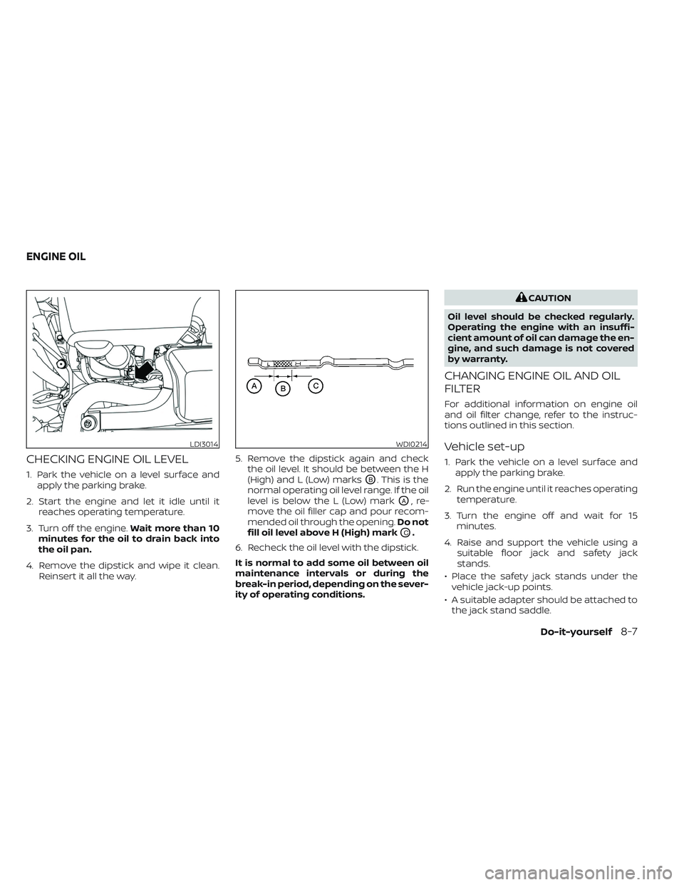
CHECKING ENGINE OIL LEVEL
1. Park the vehicle on a level surface andapply the parking brake.
2. Start the engine and let it idle until it reaches operating temperature.
3. Turn off the engine. Wait more than 10
minutes for the oil to drain back into
the oil pan.
4. Remove the dipstick and wipe it clean. Reinsert it all the way. 5. Remove the dipstick again and check
the oil level. It should be between the H
(High) and L (Low) marksOB. This is the
normal operating oil level range. If the oil
level is below the L (Low) mark
OA,re-
move the oil filler cap and pour recom-
mended oil through the opening. Do not
fill oil level above H (High) mark
OC.
6. Recheck the oil level with the dipstick.
It is normal to add some oil between oil
maintenance intervals or during the
break-in period, depending on the sever-
ity of operating conditions.
CAUTION
Oil level should be checked regularly.
Operating the engine with an insuffi-
cient amount of oil can damage the en-
gine, and such damage is not covered
by warranty.
CHANGING ENGINE OIL AND OIL
FILTER
For additional information on engine oil
and oil filter change, refer to the instruc-
tions outlined in this section.
Vehicle set-up
1. Park the vehicle on a level surface and apply the parking brake.
2. Run the engine until it reaches operating temperature.
3. Turn the engine off and wait for 15 minutes.
4. Raise and support the vehicle using a suitable floor jack and safety jack
stands.
• Place the safety jack stands under the vehicle jack-up points.
• A suitable adapter should be attached to the jack stand saddle.
LDI3014WDI0214
ENGINE OIL
Do-it-yourself8-7
Page 544 of 647
CAUTION
Be sure to remove any old gasket ma-
terial remaining on the sealing surface
of the engine. Failure to do so could
lead to an oil leak and engine damage.
• The dipstick must be inserted in
place to prevent oil spillage from the
dipstick hole when filling the engine
with oil.
6. Coat the gasket on the new filter with clean engine oil.
7. Screw in the oil filter clockwise until a slight resistance is felt, then tighten addi-
tionally more than 2/3 turn.
Oil filter tightening torque: 15.0 to 21.0 N·m (11 to 15 f t-lb)
8. Clean and re-install the drain plug with a new washer. Securely tighten the drain
plug with a wrench. Do not use exces-
sive force.
Drain plug tightening torque: 29.4 to 39.2 N·m (22 to 29 f t-lb)
9. Refill the engine with the recommended oil through the oil filler opening, and in-
stall the oil filler cap securely. For additional information about drain and
refill capacity, see “Recommended fluids/
lubricants and capacities” (P. 10-2). The
drain and refill capacity depends on the oil
temperature and drain time. Use these
specifications for reference only. Always
use the dipstick to determine the proper
amount of oil in the engine.
10. Start the engine and check for leakage
around the drain plug and the oil filter.
Correct as required. Turn the engine off
and wait more than 15 minutes. Check
the oil level with the dipstick. Add en-
gine oil if necessary.
Af ter the operation
1. Reinstall engine protectors in reverse or-der of removal.
2. Lower the vehicle carefully to the ground.
3. Reset oil and oil filter maintenance re- minder. For additional information, see
“Vehicle information display 7 inch (18
cm) Type A” (P. 2-22) or “Vehicle informa-
tion display 12.3 inch (31 cm) Type B”
(P. 2-45).
• Dispose of waste oil and filter properly.
• Check your local regulations. When checking or replacement is required,
it is recommended that you visit a NISSAN
dealer for this service.
CAUTION
• NISSAN recommends using Genuine
NISSAN Matic R ATF. Do not mix with
other fluids.
• Do not use CVT fluid or manual trans-
mission fluid in this transmission.
Damage caused by the use of fluids
other than as recommended is not
covered under NISSAN’s New Vehicle
Limited Warranty outlined in your
Warranty Information Booklet.
• Using fluids that are not equivalent
to Genuine NISSAN Matic R ATF may
also damage the transmission. Dam-
age caused by the use of fluids other
than as recommended is not covered
under NISSAN’s New Vehicle Limited
Warranty outlined in your Warranty
Information Booklet.
The specified automatic transmission fluid
is also described on caution labels located
in the engine compartment.
AUTOMATIC TRANSMISSION FLUID
(ATF)
Do-it-yourself8-11
Page 582 of 647
Steering gear and linkage, axle and sus-
pension parts, drive shaf t boots:Check
for damage, looseness, and leakage of oil
or grease. Under severe driving conditions,
inspect more frequently.
Tire rotation: Rotate tires at the specified
interval shown in the maintenance sched-
ule. When rotating tires, check for damage
and uneven wear. Replace if necessary.
Transmission fluid/oil, differential oil
and transfer case oil: Visually inspect for
signs of leakage at specified intervals. To help ensure smooth, safe and economi-
cal driving, NISSAN provides two mainte-
nance schedules that may be used, de-
pending upon the conditions in which you
usually drive. These schedules contain
both distance and time intervals, up to
120,000 miles (192,000 km)/144 months. For
most people, the odometer reading will in-
dicate when service is needed. However, if
you drive very little, your vehicle should be
serviced at the regular time intervals
shown in the schedule.
Af ter 120,000 miles (192,000 km)/144
months, continue maintenance at the
same mileage/time intervals.
ADDITIONAL MAINTENANCE ITEMS
FOR SEVERE OPERATING
CONDITIONS
Additional maintenance items for severe
operating conditions
should be per-
formed on vehicles that are driven under
especially demanding conditions. Addi-
tional maintenance items should be per-
formed if you primarily operate your vehicle
under the following conditions:
• Repeated short trips of less than 5 miles (8 km). • Repeated short trips of less than 10 miles
(16 km) with outside temperatures re-
maining below freezing.
• Operating in hot weather in stop-and-go “rush hour” traffic.
• Extensive idling and/or low speed driving for long distances, such as police, taxi or
door-to-door delivery use.
• Driving in dusty conditions.
• Driving on rough, muddy or salt spread roads.
• Towing a trailer, using a camper or using a car-top carrier.
If your vehicle is mainly operated under the
severe conditions, follow the severe use
maintenance intervals shown in the main-
tenance schedule.OIL CONTROL SYSTEM
Your vehicle is equipped with oil control
system. It calculates engine oil and filter
change intervals based on driving condi-
tions. Driving in the following severe condi-
tions will shorten the engine oil and filter
change interval.
MAINTENANCE SCHEDULES
Maintenance and schedules9-7