ECO mode NISSAN PATROL 2000 Electronic User Guide
[x] Cancel search | Manufacturer: NISSAN, Model Year: 2000, Model line: PATROL, Model: NISSAN PATROL 2000Pages: 1033, PDF Size: 30.71 MB
Page 66 of 1033
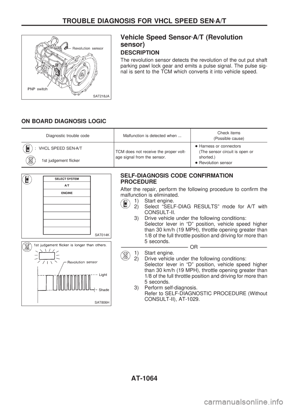
Vehicle Speed SensorzA/T (Revolution
sensor)
DESCRIPTION
The revolution sensor detects the revolution of the out put shaft
parking pawl lock gear and emits a pulse signal. The pulse sig-
nal is sent to the TCM which converts it into vehicle speed.
ON BOARD DIAGNOSIS LOGIC
Diagnostic trouble code Malfunction is detected when ...Check items
(Possible cause)
: VHCL SPEED SENzA/T
TCM does not receive the proper volt-
age signal from the sensor.+Harness or connectors
(The sensor circuit is open or
shorted.)
+Revolution sensor
: 1st judgement flicker
SELF-DIAGNOSIS CODE CONFIRMATION
PROCEDURE
After the repair, perform the following procedure to confirm the
malfunction is eliminated.
1) Start engine.
2) Select ªSELF-DIAG RESULTSº mode for A/T with
CONSULT-II.
3) Drive vehicle under the following conditions:
Selector lever in ªDº position, vehicle speed higher
than 30 km/h (19 MPH), throttle opening greater than
1/8 of the full throttle position and driving for more than
5 seconds.
-------------------------------------------------------------------------------------------------------------------------------------------------------------------------------------------------------------------------------------------------OR-------------------------------------------------------------------------------------------------------------------------------------------------------------------------------------------------------------------------------------------------
1) Start engine.
2) Drive vehicle under the following conditions:
Selector lever in ªDº position, vehicle speed higher
than 30 km/h (19 MPH), throttle opening greater than
1/8 of the full throttle position and driving for more than
5 seconds.
3) Perform self-diagnosis.
Refer to SELF-DIAGNOSTIC PROCEDURE (Without
CONSULT-II), AT-1029.
SAT218JA
SAT014K
SAT806H
TROUBLE DIAGNOSIS FOR VHCL SPEED SENzA/T
AT-1064
Page 70 of 1033
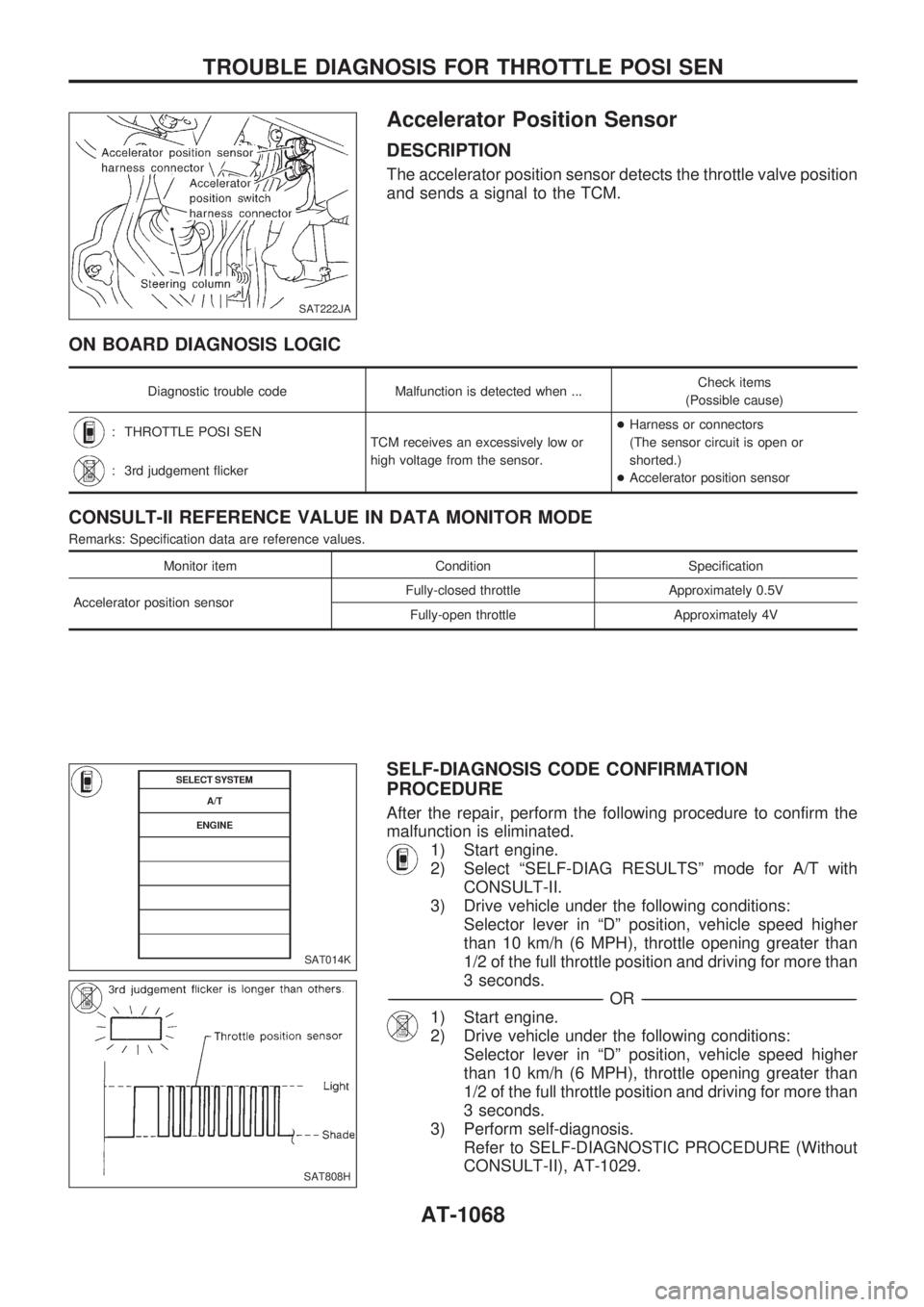
Accelerator Position Sensor
DESCRIPTION
The accelerator position sensor detects the throttle valve position
and sends a signal to the TCM.
ON BOARD DIAGNOSIS LOGIC
Diagnostic trouble code Malfunction is detected when ...Check items
(Possible cause)
: THROTTLE POSI SEN
TCM receives an excessively low or
high voltage from the sensor.+Harness or connectors
(The sensor circuit is open or
shorted.)
+Accelerator position sensor
: 3rd judgement flicker
CONSULT-II REFERENCE VALUE IN DATA MONITOR MODE
Remarks: Specification data are reference values.
Monitor item Condition Specification
Accelerator position sensorFully-closed throttle Approximately 0.5V
Fully-open throttle Approximately 4V
SELF-DIAGNOSIS CODE CONFIRMATION
PROCEDURE
After the repair, perform the following procedure to confirm the
malfunction is eliminated.
1) Start engine.
2) Select ªSELF-DIAG RESULTSº mode for A/T with
CONSULT-II.
3) Drive vehicle under the following conditions:
Selector lever in ªDº position, vehicle speed higher
than 10 km/h (6 MPH), throttle opening greater than
1/2 of the full throttle position and driving for more than
3 seconds.
-------------------------------------------------------------------------------------------------------------------------------------------------------------------------------------------------------------------------------------------------OR-------------------------------------------------------------------------------------------------------------------------------------------------------------------------------------------------------------------------------------------------
1) Start engine.
2) Drive vehicle under the following conditions:
Selector lever in ªDº position, vehicle speed higher
than 10 km/h (6 MPH), throttle opening greater than
1/2 of the full throttle position and driving for more than
3 seconds.
3) Perform self-diagnosis.
Refer to SELF-DIAGNOSTIC PROCEDURE (Without
CONSULT-II), AT-1029.
SAT222JA
SAT014K
SAT808H
TROUBLE DIAGNOSIS FOR THROTTLE POSI SEN
AT-1068
Page 84 of 1033
Engine Speed Signal
DESCRIPTION
The engine speed signal is sent from the ECM to the TCM.
ON BOARD DIAGNOSIS LOGIC
Diagnostic trouble code Malfunction is detected when ...Check items
(Possible cause)
:
ENGINE SPEED SIG
TCM does not receive the proper volt-
age signal from ECM.+Harness or connectors
(The sensor circuit is open or
shorted.)
:
9th judgement flicker
SELF-DIAGNOSIS CODE CONFIRMATION
PROCEDURE
After the repair, perform the following procedure to confirm the
malfunction is eliminated.
1) Start engine.
2) Select ªSELF-DIAG RESULTSº mode for A/T with
CONSULT-II.
3) Drive vehicle under the following conditions:
Selector lever in ªDº position, vehicle speed higher
than 10 km/h (6 MPH), throttle opening greater than
1/8 of the full throttle position and driving for more than
10 seconds.
-------------------------------------------------------------------------------------------------------------------------------------------------------------------------------------------------------------------------------------------------OR-------------------------------------------------------------------------------------------------------------------------------------------------------------------------------------------------------------------------------------------------
1) Start engine.
2) Drive vehicle under the following conditions:
Selector lever in ªDº position, vehicle speed higher
than 10 km/h (6 MPH), throttle opening greater than
1/8 of the full throttle position and driving for more than
10 seconds.
3) Perform self-diagnosis.
Refer to SELF-DIAGNOSTIC PROCEDURE (Without
CONSULT-II), AT-1029.
SAT014K
SAT823H
TROUBLE DIAGNOSIS FOR ENGINE SPEED SIG
AT-1082
Page 89 of 1033
Description
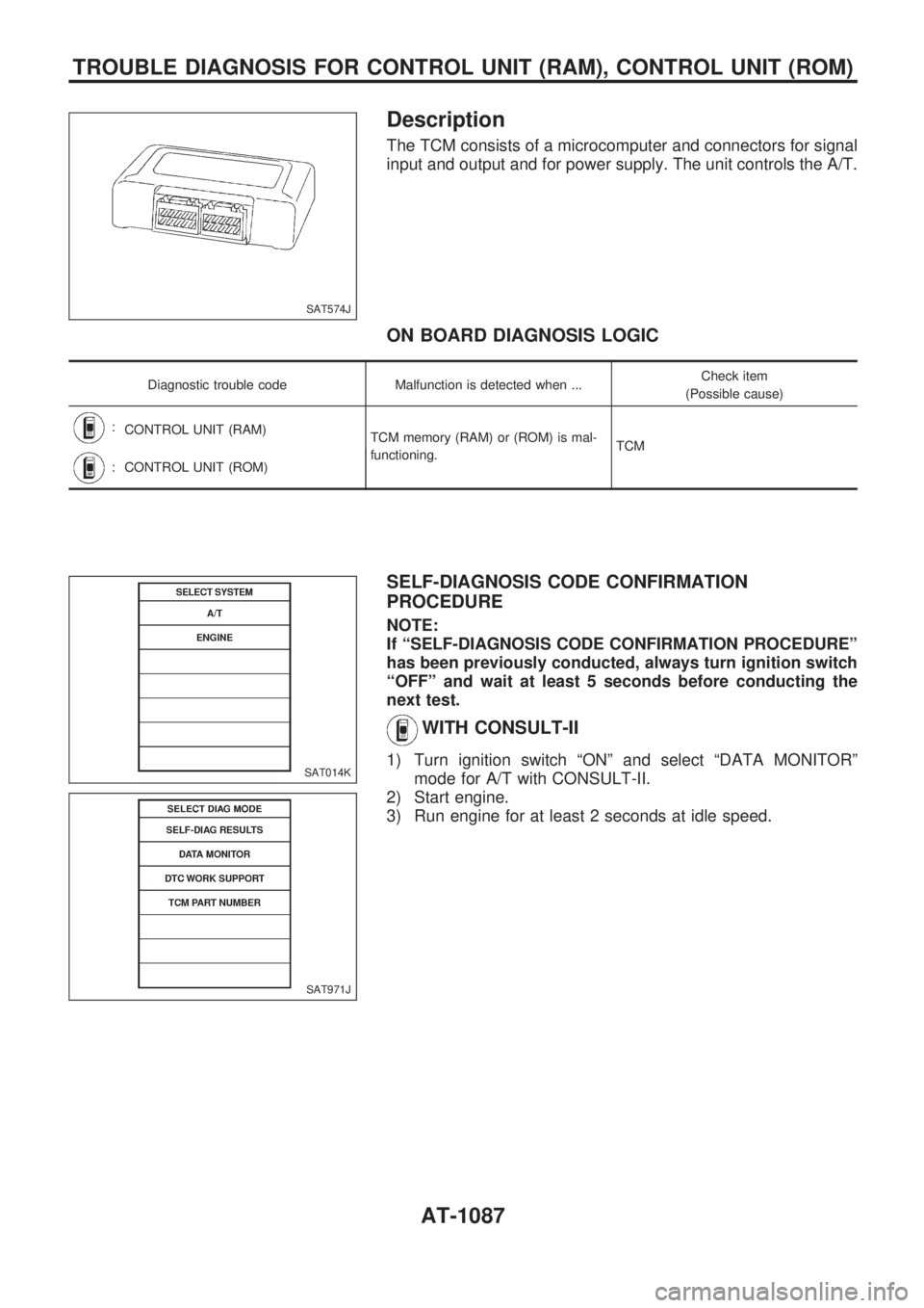
The TCM consists of a microcomputer and connectors for signal
input and output and for power supply. The unit controls the A/T.
ON BOARD DIAGNOSIS LOGIC
Diagnostic trouble code Malfunction is detected when ...Check item
(Possible cause)
:
CONTROL UNIT (RAM)
TCM memory (RAM) or (ROM) is mal-
functioning.TCM
:CONTROL UNIT (ROM)
SELF-DIAGNOSIS CODE CONFIRMATION
PROCEDURE
NOTE:
If ªSELF-DIAGNOSIS CODE CONFIRMATION PROCEDUREº
has been previously conducted, always turn ignition switch
ªOFFº and wait at least 5 seconds before conducting the
next test.
WITH CONSULT-II
1) Turn ignition switch ªONº and select ªDATA MONITORº
mode for A/T with CONSULT-II.
2) Start engine.
3) Run engine for at least 2 seconds at idle speed.
SAT574J
SAT014K
SAT971J
TROUBLE DIAGNOSIS FOR CONTROL UNIT (RAM), CONTROL UNIT (ROM)
AT-1087
Page 91 of 1033
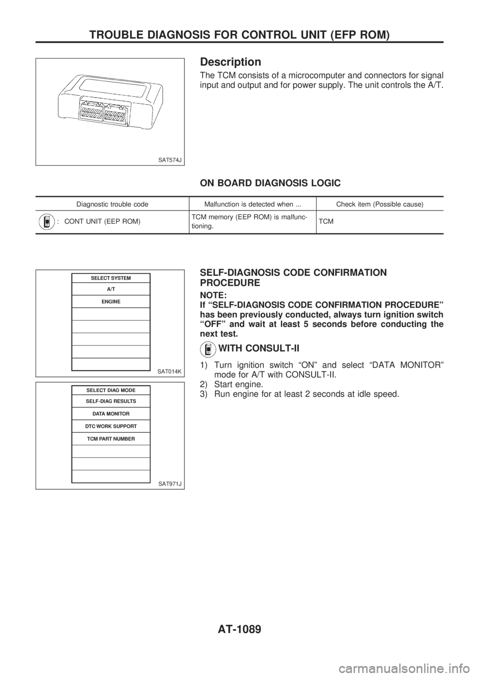
Description
The TCM consists of a microcomputer and connectors for signal
input and output and for power supply. The unit controls the A/T.
ON BOARD DIAGNOSIS LOGIC
Diagnostic trouble code Malfunction is detected when ... Check item (Possible cause)
: CONT UNIT (EEP ROM)TCM memory (EEP ROM) is malfunc-
tioning.TCM
SELF-DIAGNOSIS CODE CONFIRMATION
PROCEDURE
NOTE:
If ªSELF-DIAGNOSIS CODE CONFIRMATION PROCEDUREº
has been previously conducted, always turn ignition switch
ªOFFº and wait at least 5 seconds before conducting the
next test.
WITH CONSULT-II
1) Turn ignition switch ªONº and select ªDATA MONITORº
mode for A/T with CONSULT-II.
2) Start engine.
3) Run engine for at least 2 seconds at idle speed.
SAT574J
SAT014K
SAT971J
TROUBLE DIAGNOSIS FOR CONTROL UNIT (EFP ROM)
AT-1089
Page 92 of 1033
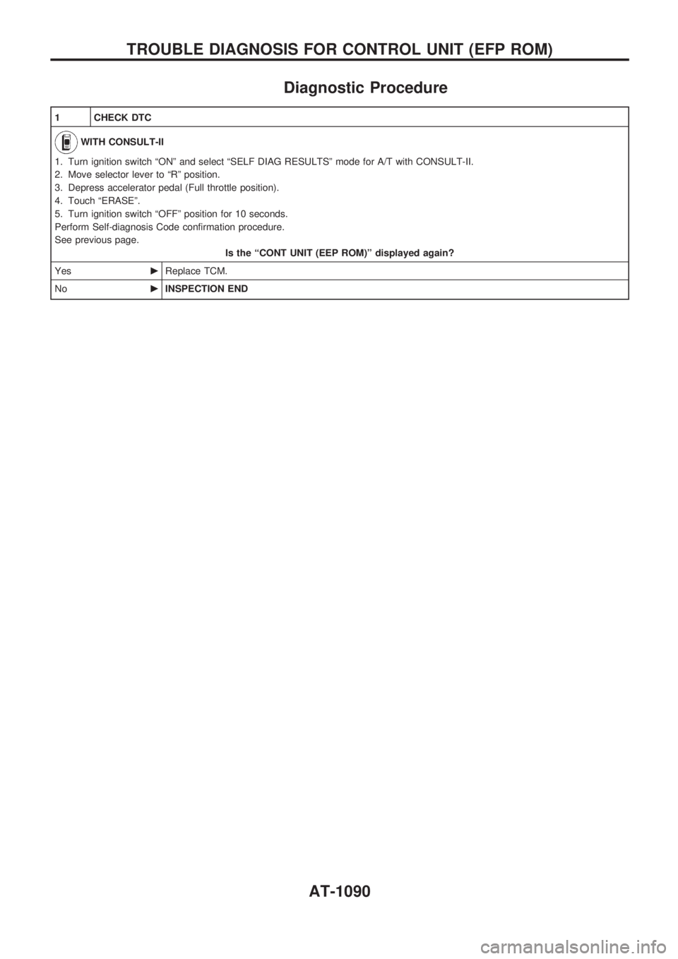
Diagnostic Procedure
1 CHECK DTC
WITH CONSULT-II
1. Turn ignition switch ªONº and select ªSELF DIAG RESULTSº mode for A/T with CONSULT-II.
2. Move selector lever to ªRº position.
3. Depress accelerator pedal (Full throttle position).
4. Touch ªERASEº.
5. Turn ignition switch ªOFFº position for 10 seconds.
Perform Self-diagnosis Code confirmation procedure.
See previous page.
Is the ªCONT UNIT (EEP ROM)º displayed again?
YescReplace TCM.
NocINSPECTION END
TROUBLE DIAGNOSIS FOR CONTROL UNIT (EFP ROM)
AT-1090
Page 208 of 1033
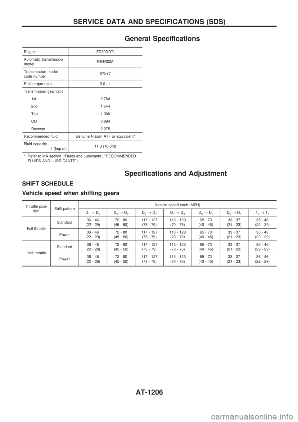
General Specifications
Engine ZD30DDTi
Automatic transmission
modelRE4R03A
Transmission model
code number57X17
Stall torque ratio 2.0 : 1
Transmission gear ratio
1st 2.784
2nd 1.544
Top 1.000
OD 0.694
Reverse 2.275
Recommended fluid Genuine Nissan ATF or equivalent*
Fluid capacity
!(Imp qt)11.8 (10-3/8)
*: Refer to MA section (ªFluids and Lubricantsº, ªRECOMMENDED
FLUIDS AND LUBRICANTSº).
Specifications and Adjustment
SHIFT SCHEDULE
Vehicle speed when shifting gears
Throttle posi-
tionShift patternVehicle speed km/h (MPH)
D
1®D2D2®D3D3®D4D4®D3D3®D2D2®D112®11
Full throttleStandard36-46
(22 - 29)72-80
(45 - 50)117 - 127
(73 - 79)113 - 123
(70 - 76)65-73
(40 - 45)33-37
(21 - 23)36-46
(22 - 29)
Power36-46
(22 - 29)72-80
(45 - 50)117 - 127
(73 - 79)113 - 123
(70 - 76)65-73
(40 - 45)33-37
(21 - 23)36-46
(22 - 29)
Half throttleStandard36-46
(22 - 29)72-80
(45 - 50)117 - 127
(73 - 79)113 - 123
(70 - 76)65-73
(40 - 45)33-37
(21 - 23)36-46
(22 - 29)
Power36-46
(22 - 29)72-80
(45 - 50)117 - 127
(73 - 79)113 - 123
(70 - 76)65-73
(40 - 45)33-37
(21 - 23)36-46
(22 - 29)
SERVICE DATA AND SPECIFICATIONS (SDS)
AT-1206
Page 220 of 1033
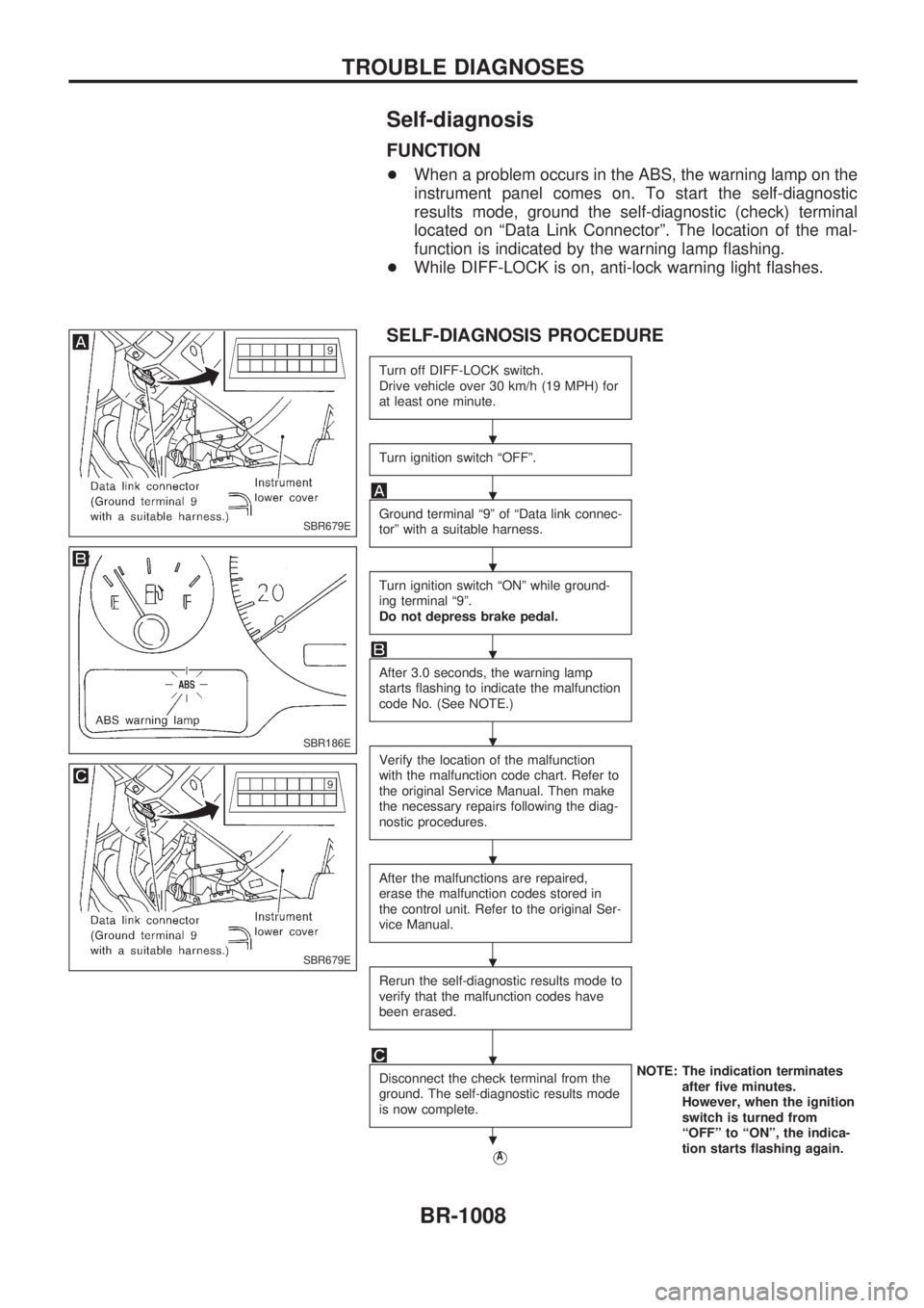
Self-diagnosis
FUNCTION
+When a problem occurs in the ABS, the warning lamp on the
instrument panel comes on. To start the self-diagnostic
results mode, ground the self-diagnostic (check) terminal
located on ªData Link Connectorº. The location of the mal-
function is indicated by the warning lamp flashing.
+While DIFF-LOCK is on, anti-lock warning light flashes.
SELF-DIAGNOSIS PROCEDURE
Turn off DIFF-LOCK switch.
Drive vehicle over 30 km/h (19 MPH) for
at least one minute.
Turn ignition switch ªOFFº.
Ground terminal ª9º of ªData link connec-
torº with a suitable harness.
Turn ignition switch ªONº while ground-
ing terminal ª9º.
Do not depress brake pedal.
After 3.0 seconds, the warning lamp
starts flashing to indicate the malfunction
code No. (See NOTE.)
Verify the location of the malfunction
with the malfunction code chart. Refer to
the original Service Manual. Then make
the necessary repairs following the diag-
nostic procedures.
After the malfunctions are repaired,
erase the malfunction codes stored in
the control unit. Refer to the original Ser-
vice Manual.
Rerun the self-diagnostic results mode to
verify that the malfunction codes have
been erased.
Disconnect the check terminal from the
ground. The self-diagnostic results mode
is now complete.NOTE: The indication terminates
after five minutes.
However, when the ignition
switch is turned from
ªOFFº to ªONº, the indica-
tion starts flashing again.
VA
SBR679E
SBR186E
SBR679E
.
.
.
.
.
.
.
.
.
TROUBLE DIAGNOSES
BR-1008
Page 222 of 1033
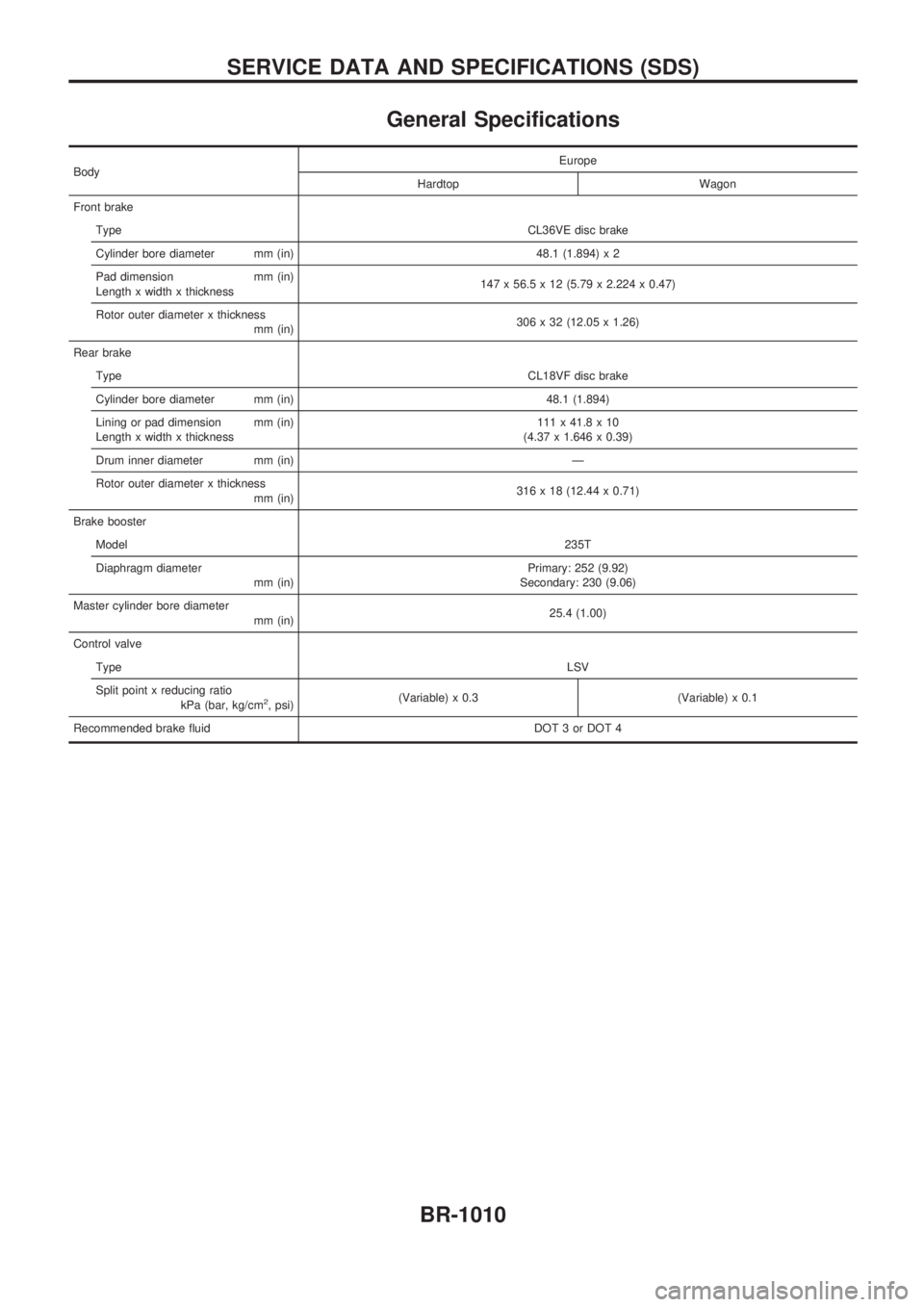
General Specifications
BodyEurope
Hardtop Wagon
Front brake
TypeCL36VE disc brake
Cylinder bore diameter mm (in) 48.1 (1.894) x 2
Pad dimension mm (in)
Length x width x thickness147 x 56.5 x 12 (5.79 x 2.224 x 0.47)
Rotor outer diameter x thickness
mm (in)306 x 32 (12.05 x 1.26)
Rear brake
TypeCL18VF disc brake
Cylinder bore diameter mm (in) 48.1 (1.894)
Lining or pad dimension mm (in)
Length x width x thickness111 x 41.8 x 10
(4.37 x 1.646 x 0.39)
Drum inner diameter mm (in) Ð
Rotor outer diameter x thickness
mm (in)316 x 18 (12.44 x 0.71)
Brake booster
Model235T
Diaphragm diameter
mm (in)Primary: 252 (9.92)
Secondary: 230 (9.06)
Master cylinder bore diameter
mm (in)25.4 (1.00)
Control valve
TypeLSV
Split point x reducing ratio
kPa (bar, kg/cm
2, psi)(Variable) x 0.3 (Variable) x 0.1
Recommended brake fluid DOT 3 or DOT 4
SERVICE DATA AND SPECIFICATIONS (SDS)
BR-1010
Page 265 of 1033
DTC and MI Detection Logic
When a malfunction is detected, the malfunction (DTC) is stored in the ECM memory.
The MI will light up each time the ECM detects malfunction. For diagnostic items causing the MI to light up,
refer to ªTROUBLE DIAGNOSIS Ð INDEXº, EC-1006.
Diagnostic Trouble Code (DTC)
HOW TO READ DTC
The DTC can be read by the following methods.
Without CONSULT-II
ECM displays the DTC by a set of four digit numbers with MI illumination in the diagnostic test mode II
(Self-diagnostic results). Example: 0102, 0407, 1004, etc.
With CONSULT-II
CONSULT-II displays the DTC in ªSELF-DIAG RESULTSº mode. Examples: ªCRANK POS SEN (TDC)º, etc.
+Output of the trouble code means that the indicated circuit has a malfunction. However, in the
Mode II it does not indicate whether the malfunction is still occurring or occurred in the past and
returned to normal.
CONSULT-II can identify them. Therefore, using CONSULT-II (if available) is recommended.
HOW TO ERASE DTC
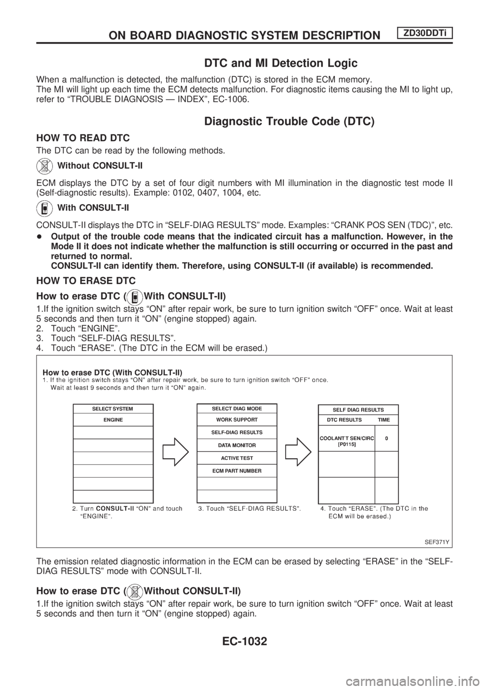
How to erase DTC (
With CONSULT-II)
1.If the ignition switch stays ªONº after repair work, be sure to turn ignition switch ªOFFº once. Wait at least
5 seconds and then turn it ªONº (engine stopped) again.
2. Touch ªENGINEº.
3. Touch ªSELF-DIAG RESULTSº.
4. Touch ªERASEº. (The DTC in the ECM will be erased.)
The emission related diagnostic information in the ECM can be erased by selecting ªERASEº in the ªSELF-
DIAG RESULTSº mode with CONSULT-II.
How to erase DTC (Without CONSULT-II)
1.If the ignition switch stays ªONº after repair work, be sure to turn ignition switch ªOFFº once. Wait at least
5 seconds and then turn it ªONº (engine stopped) again.
SEF371Y
ON BOARD DIAGNOSTIC SYSTEM DESCRIPTIONZD30DDTi
EC-1032