ignition NISSAN PATROL 2000 Electronic Repair Manual
[x] Cancel search | Manufacturer: NISSAN, Model Year: 2000, Model line: PATROL, Model: NISSAN PATROL 2000Pages: 1033, PDF Size: 30.71 MB
Page 1007 of 1033
![NISSAN PATROL 2000 Electronic Repair Manual If no malfunction is detected on ªSELF-DIAG [CURRENT]º even
though malfunction is detected by the ªAIR BAGº warning lamp,
go to DIAGNOSTIC PROCEDURE 4, page RS-1040 to diagnose
the following cases](/img/5/57367/w960_57367-1006.png "NISSAN PATROL 2000 Electronic Repair Manual If no malfunction is detected on ªSELF-DIAG [CURRENT]º even
though malfunction is detected by the ªAIR BAGº warning lamp,
go to DIAGNOSTIC PROCEDURE 4, page RS-1040 to diagnose
the following cases")
If no malfunction is detected on ªSELF-DIAG [CURRENT]º even
though malfunction is detected by the ªAIR BAGº warning lamp,
go to DIAGNOSTIC PROCEDURE 4, page RS-1040 to diagnose
the following cases:
+Self-diagnostic result ªSELF-DIAG [PAST] (previously stored
in the memory) might not be erased after repair.
+The SRS system malfunctions intermittently.
8. Touch ªPRINTº.
9. Compare diagnostic codes to the CONSULT-II DIAGNOS-
TIC CODE CHART, page RS-1036.
10. Touch ªBACKº key of CONSULT-II until SELECT SYSTEM
appears in order to return to User mode from Diagnosis
mode.
11. Turn ignition switch ªOFFº, then turn of and disconnect CON-
SULT-II and both battery cables.
12. Repair the system as outlined by the ªRepair orderº in CON-
SULT-II DIAGNOSTIC CODE CHART, that corresponds to
the self-diagnostic result. For replacement procedure of com-
ponent parts, refer to RS-1008 and ªRemoval and Installa-
tionº in RS section of Service Manual (Pub. No. SM7E-
2Y61G0 or SM7E-2Y61G1).
13. After repairing the system, go to DIAGNOSTIC PROCE-
DURE 3 for final checking, page RS-1038.
SRS701
TROUBLE DIAGNOSES Ð Supplemental Restraint System (SRS)
Self-diagnosis (Cont'd)
RS-1035
Page 1010 of 1033
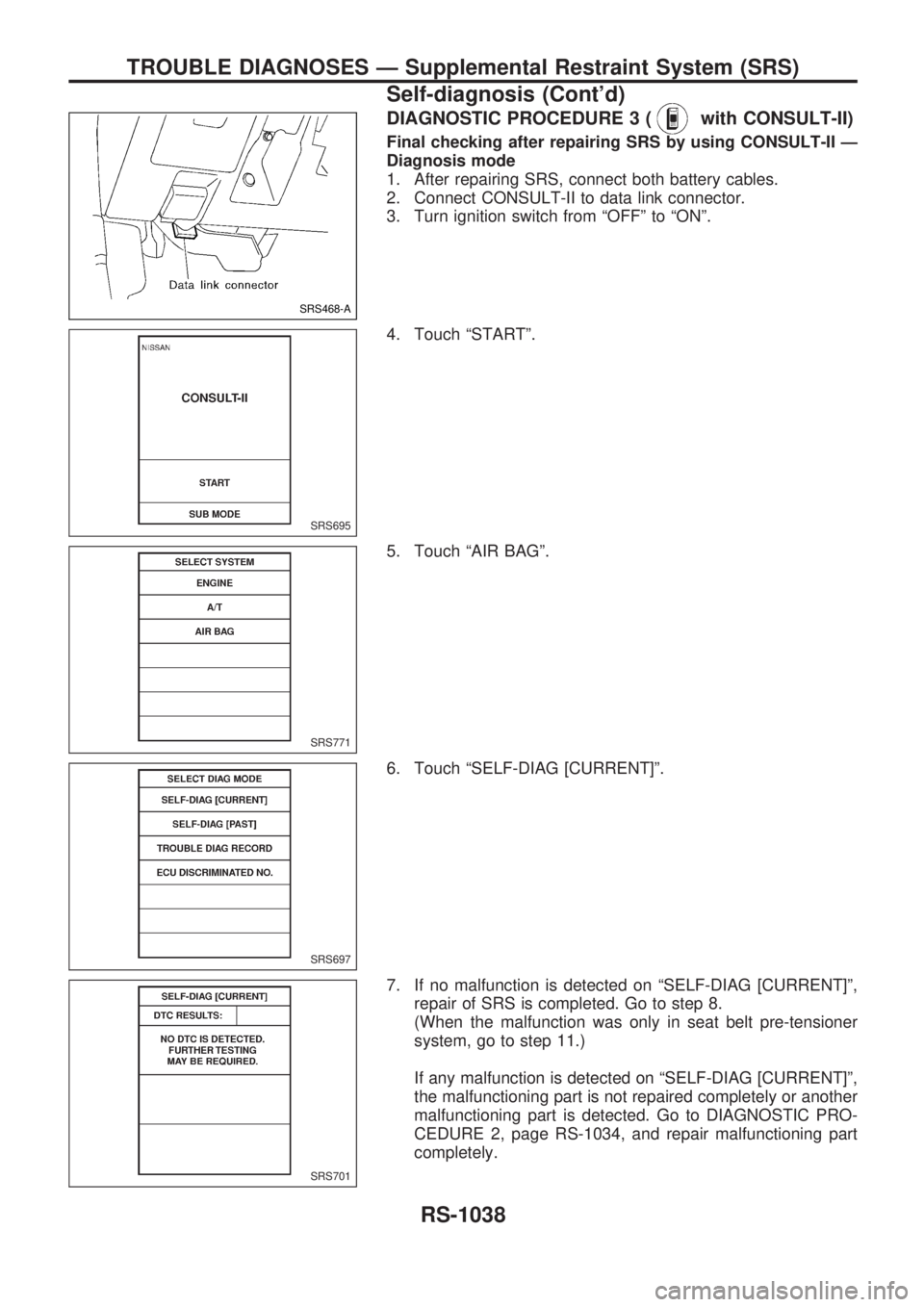
DIAGNOSTIC PROCEDURE 3 (with CONSULT-II)
Final checking after repairing SRS by using CONSULT-II Ð
Diagnosis mode
1. After repairing SRS, connect both battery cables.
2. Connect CONSULT-II to data link connector.
3. Turn ignition switch from ªOFFº to ªONº.
4. Touch ªSTARTº.
5. Touch ªAIR BAGº.
6. Touch ªSELF-DIAG [CURRENT]º.
7. If no malfunction is detected on ªSELF-DIAG [CURRENT]º,
repair of SRS is completed. Go to step 8.
(When the malfunction was only in seat belt pre-tensioner
system, go to step 11.)
If any malfunction is detected on ªSELF-DIAG [CURRENT]º,
the malfunctioning part is not repaired completely or another
malfunctioning part is detected. Go to DIAGNOSTIC PRO-
CEDURE 2, page RS-1034, and repair malfunctioning part
completely.
SRS468-A
SRS695
SRS771
SRS697
SRS701
TROUBLE DIAGNOSES Ð Supplemental Restraint System (SRS)
Self-diagnosis (Cont'd)
RS-1038
Page 1011 of 1033
![NISSAN PATROL 2000 Electronic Repair Manual 8. Touch ªERASEº.
NOTE:
Touch ªERASEº to clear the memory of the malfunction
(ªSELF-DIAG [PAST]º).
If the memory of the malfunction is ªSELF-DIAG [PAST]º is
not erased, the User mode shows the](/img/5/57367/w960_57367-1010.png "NISSAN PATROL 2000 Electronic Repair Manual 8. Touch ªERASEº.
NOTE:
Touch ªERASEº to clear the memory of the malfunction
(ªSELF-DIAG [PAST]º).
If the memory of the malfunction is ªSELF-DIAG [PAST]º is
not erased, the User mode shows the")
8. Touch ªERASEº.
NOTE:
Touch ªERASEº to clear the memory of the malfunction
(ªSELF-DIAG [PAST]º).
If the memory of the malfunction is ªSELF-DIAG [PAST]º is
not erased, the User mode shows the system malfunction by
the operation of the warning lamp even if the malfunction is
repaired completely.
9. Touch ªBACKº key of CONSULT-II to select ªSELF-DIAG
[PAST]º in the ªSELECT DIAG MODEº screen. Touch ªSELF-
DIAG [PAST]º.
10. Check that no malfunction is detected on ªSELF-DIAG
[PAST]º.
NOTE:
Past malfunction for seat belt pre-tensioner system will not
be displayed on ªSELF-DIAG [PAST]º.
11. Touch ªBACKº key of CONSULT-II until SELECT SYSTEM
appears.
12. Turn ignition switch ªOFFº, then turn off and disconnect
CONSULT-II.
13. Go to DIAGNOSTIC PROCEDURE 1, page RS-1032 to
checkSRS operation by using ªAIR BAGº warning lamp with
User mode.
SRS773
SRS697
SRS702
TROUBLE DIAGNOSES Ð Supplemental Restraint System (SRS)
Self-diagnosis (Cont'd)
RS-1039
Page 1012 of 1033
![NISSAN PATROL 2000 Electronic Repair Manual DIAGNOSTIC PROCEDURE 4 (Continued from
DIAGNOSTIC PROCEDURE 2)
Inspecting SRS malfunctioning record
Is it the first time for maintenance of
SRS?
Yes
cNo
ªSELF-DIAG [PAST]º
(which was previously
ente](/img/5/57367/w960_57367-1011.png "NISSAN PATROL 2000 Electronic Repair Manual DIAGNOSTIC PROCEDURE 4 (Continued from
DIAGNOSTIC PROCEDURE 2)
Inspecting SRS malfunctioning record
Is it the first time for maintenance of
SRS?
Yes
cNo
ªSELF-DIAG [PAST]º
(which was previously
ente")
DIAGNOSTIC PROCEDURE 4 (Continued from
DIAGNOSTIC PROCEDURE 2)
Inspecting SRS malfunctioning record
Is it the first time for maintenance of
SRS?
Yes
cNo
ªSELF-DIAG [PAST]º
(which was previously
entered) is still retained in
memory.
Go to DIAGNOSTIC PRO-
CEDURE 3 (RS-1038).
Go to DIAGNOSTIC PROCEDURE 5
(RS-1040).
DIAGNOSTIC PROCEDURE 5 (with CONSULT-II)
Inspecting SRS intermittent malfunction by using CON-
SULT-II Ð Diagnosis mode
1. Turn ignition switch ªOFFº.
2. Connect CONSULT-II to data link connector.
3. Turn ignition switch ªONº.
4. Touch ªSTARTº.
5. Touch ªAIR BAGº.
SRS468-A
SRS695
SRS771
.
TROUBLE DIAGNOSES Ð Supplemental Restraint System (SRS)
Self-diagnosis (Cont'd)
RS-1040
Page 1014 of 1033
10. Touch ªPRINTº.
11. Compare diagnostic codes to the INTERMITTENT MAL-
FUNCTION DIAGNOSTIC CODE CHART, page RS-1043.
12. Touch ªBACKº key of CONSULT-II until SELECT SYSTEM
appears.
13. Turn ignition switch ªOFFº, then turn off and disconnect
CONSULT-II and both battery cables.
14. Repair the system as outlined by the ªRepair orderº in
INTERMITTENT MALFUNCTION DIAGNOSTIC CODE
CHART, that corresponds to the self-diagnosis result. For
replacement procedure of component parts, refer to RS-1008
and ªRemoval and Installationº in RS section of Service
Manual (Pub. No. SM7E-2Y61G0 or SM7E-2Y61G1).
15. Go to DIAGNOSTIC PROCEDURE 3, page RS-1038.
TROUBLE DIAGNOSES Ð Supplemental Restraint System (SRS)
Self-diagnosis (Cont'd)
RS-1042
Page 1016 of 1033
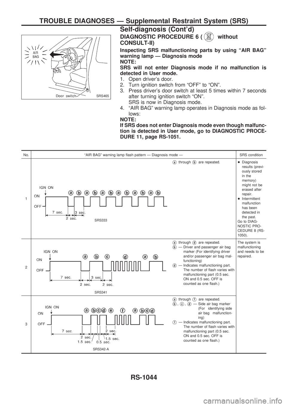
DIAGNOSTIC PROCEDURE 6 (without
CONSULT-II)
Inspecting SRS malfunctioning parts by using ªAIR BAGº
warning lamp Ð Diagnosis mode
NOTE:
SRS will not enter Diagnosis mode if no malfunction is
detected in User mode.
1. Open driver's door.
2. Turn ignition switch from ªOFFº to ªONº.
3. Press driver's door switch at least 5 times within 7 seconds
after turning ignition switch ªONº.
SRS is now in Diagnosis mode.
4. ªAIR BAGº warning lamp operates in Diagnosis mode as fol-
lows:
NOTE:
If SRS does not enter Diagnosis mode even though malfunc-
tion is detected in User mode, go to DIAGNOSTIC PROCE-
DURE 11, page RS-1051.
No. ªAIR BAGº warning lamp flash pattern Ð Diagnosis mode Ð SRS condition
1
SRS333
VathroughVbare repeated.+Diagnosis
results (previ-
ously stored
in the
memory)
might not be
erased after
repair.
+Intermittent
malfunction
has been
detected in
the past.
Go to DIAG-
NOSTIC PRO-
CEDURE 8 (RS-
1050).
2
SRS341
VathroughVdare repeated.
VbÐ Driver and passenger air bag
marker (For identifying driver
and/or passenger air bag mal-
functioning)
VdÐ Indicates malfunctioning part.
The number of flash varies with
malfunctioning part (0.5 sec.
ON and 0.5 sec. OFF is
counted as one flash.)The system is
malfunctioning
and needs to be
repaired.
3
SRS342-A
VathroughVfare repeated.
Vb,Vc,VdÐ Side air bag marker
(For identifying side
air bag malfunction-
ing)
VfÐ Indicates malfunctioning part.
The number of flash varies with
malfunctioning part (0.5 sec.
ON and 0.5 sec. OFF is
counted as one flash.)
SRS465
TROUBLE DIAGNOSES Ð Supplemental Restraint System (SRS)
Self-diagnosis (Cont'd)
RS-1044
Page 1017 of 1033
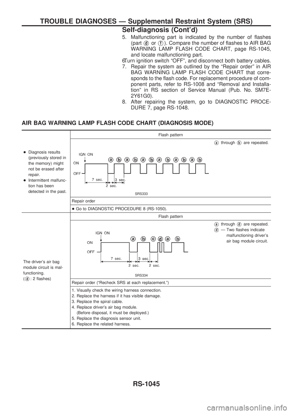
5. Malfunctioning part is indicated by the number of flashes
(part
VdorVf). Compare the number of flashes to AIR BAG
WARNING LAMP FLASH CODE CHART, page RS-1045,
and locate malfunctioning part.
6.Turn ignition switch ªOFFº, and disconnect both battery cables.
7. Repair the system as outlined by the ªRepair orderº in AIR
BAG WARNING LAMP FLASH CODE CHART that corre-
sponds to the flash code. For replacement procedure of com-
ponent parts, refer to RS-1008 and ªRemoval and Installa-
tionº in RS section of Service Manual (Pub. No. SM7E-
2Y61G0).
8. After repairing the system, go to DIAGNOSTIC PROCE-
DURE 7, page RS-1048.
AIR BAG WARNING LAMP FLASH CODE CHART (DIAGNOSIS MODE)
+Diagnosis results
(previously stored in
the memory) might
not be erased after
repair.
+Intermittent malfunc-
tion has been
detected in the past.Flash pattern
SRS333
VathroughVbare repeated.
Repair order
+Go to DIAGNOSTIC PROCEDURE 8 (RS-1050).
The driver's air bag
module circuit is mal-
functioning.
(
Vd: 2 flashes)Flash patternSRS334
VathroughVdare repeated.
VdÐ Two flashes indicate
malfunctioning driver's
air bag module circuit.
Repair order (ªRecheck SRS at each replacement.º)
1. Visually check the wiring harness connection.
2. Replace the harness if it has visible damage.
3. Replace the spiral cable.
4. Replace driver's air bag module.
(Before disposal, it must be deployed.)
5. Replace the diagnosis sensor unit.
6. Replace the related harness.
TROUBLE DIAGNOSES Ð Supplemental Restraint System (SRS)
Self-diagnosis (Cont'd)
RS-1045
Page 1020 of 1033
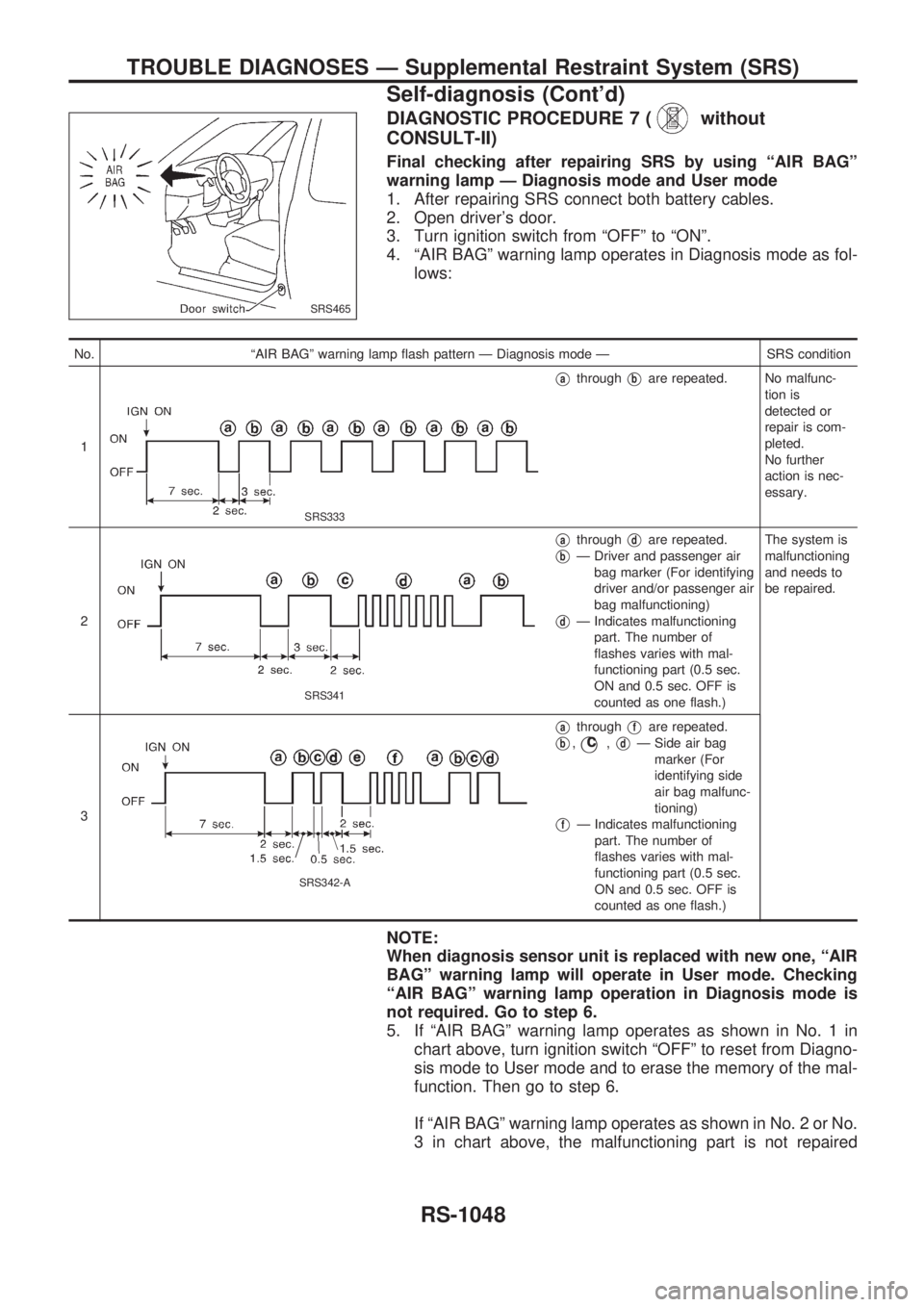
DIAGNOSTIC PROCEDURE 7 (without
CONSULT-II)
Final checking after repairing SRS by using ªAIR BAGº
warning lamp Ð Diagnosis mode and User mode
1. After repairing SRS connect both battery cables.
2. Open driver's door.
3. Turn ignition switch from ªOFFº to ªONº.
4. ªAIR BAGº warning lamp operates in Diagnosis mode as fol-
lows:
No. ªAIR BAGº warning lamp flash pattern Ð Diagnosis mode Ð SRS condition
1
SRS333
VathroughVbare repeated. No malfunc-
tion is
detected or
repair is com-
pleted.
No further
action is nec-
essary.
2
SRS341
VathroughVdare repeated.
VbÐ Driver and passenger air
bag marker (For identifying
driver and/or passenger air
bag malfunctioning)
VdÐ Indicates malfunctioning
part. The number of
flashes varies with mal-
functioning part (0.5 sec.
ON and 0.5 sec. OFF is
counted as one flash.)The system is
malfunctioning
and needs to
be repaired.
3
SRS342-A
VathroughVfare repeated.
Vb,jc,VdÐ Side air bag
marker (For
identifying side
air bag malfunc-
tioning)
VfÐ Indicates malfunctioning
part. The number of
flashes varies with mal-
functioning part (0.5 sec.
ON and 0.5 sec. OFF is
counted as one flash.)
NOTE:
When diagnosis sensor unit is replaced with new one, ªAIR
BAGº warning lamp will operate in User mode. Checking
ªAIR BAGº warning lamp operation in Diagnosis mode is
not required. Go to step 6.
5. If ªAIR BAGº warning lamp operates as shown in No. 1 in
chart above, turn ignition switch ªOFFº to reset from Diagno-
sis mode to User mode and to erase the memory of the mal-
function. Then go to step 6.
If ªAIR BAGº warning lamp operates as shown in No. 2 or No.
3 in chart above, the malfunctioning part is not repaired
SRS465
TROUBLE DIAGNOSES Ð Supplemental Restraint System (SRS)
Self-diagnosis (Cont'd)
RS-1048
Page 1021 of 1033
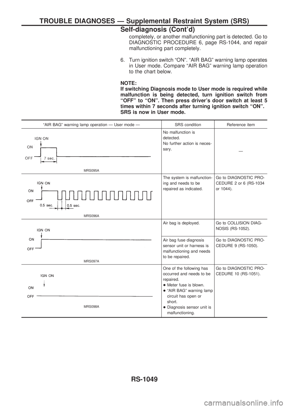
completely, or another malfunctioning part is detected. Go to
DIAGNOSTIC PROCEDURE 6, page RS-1044, and repair
malfunctioning part completely.
6. Turn ignition switch ªONº. ªAIR BAGº warning lamp operates
in User mode. Compare ªAIR BAGº warning lamp operation
to the chart below.
NOTE:
If switching Diagnosis mode to User mode is required while
malfunction is being detected, turn ignition switch from
ªOFFº to ªONº. Then press driver's door switch at least 5
times within 7 seconds after turning ignition switch ªONº.
SRS is now in User mode.
ªAIR BAGº warning lamp operation Ð User mode Ð SRS condition Reference item
MRS095A
No malfunction is
detected.
No further action is neces-
sary.
Ð
MRS096A
The system is malfunction-
ing and needs to be
repaired as indicated.Go to DIAGNOSTIC PRO-
CEDURE 2 or 6 (RS-1034
or 1044).
MRS097A
Air bag is deployed. Go to COLLISION DIAG-
NOSIS (RS-1052).
Air bag fuse diagnosis
sensor unit or harness is
malfunctioning and needs
to be repaired.Go to DIAGNOSTIC PRO-
CEDURE 9 (RS-1050).
MRS098A
One of the following has
occurred and needs to be
repaired.
+Meter fuse is blown.
+ªAIR BAGº warning lamp
circuit has open or
short.
+Diagnosis sensor unit is
malfunctioning.Go to DIAGNOSTIC PRO-
CEDURE 10 (RS-1051).
TROUBLE DIAGNOSES Ð Supplemental Restraint System (SRS)
Self-diagnosis (Cont'd)
RS-1049
Page 1023 of 1033
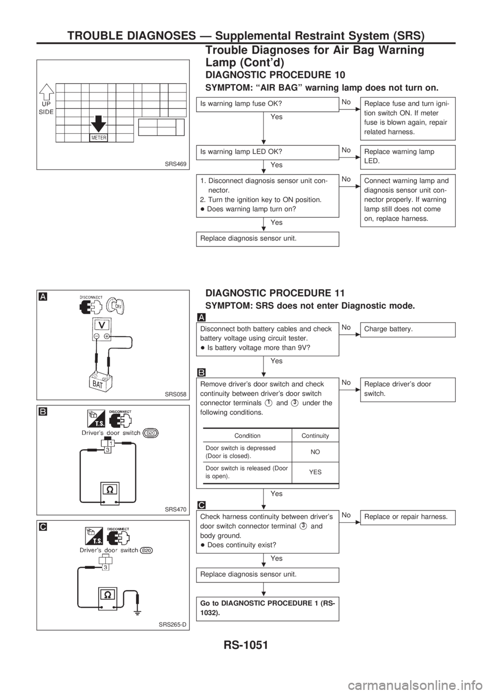
DIAGNOSTIC PROCEDURE 10
SYMPTOM: ªAIR BAGº warning lamp does not turn on.
Is warning lamp fuse OK?
YescNo
Replace fuse and turn igni-
tion switch ON. If meter
fuse is blown again, repair
related harness.
Is warning lamp LED OK?
YescNo
Replace warning lamp
LED.
1. Disconnect diagnosis sensor unit con-
nector.
2. Turn the ignition key to ON position.
+Does warning lamp turn on?
Yes
cNo
Connect warning lamp and
diagnosis sensor unit con-
nector properly. If warning
lamp still does not come
on, replace harness.
Replace diagnosis sensor unit.
DIAGNOSTIC PROCEDURE 11
SYMPTOM: SRS does not enter Diagnostic mode.
Disconnect both battery cables and check
battery voltage using circuit tester.
+Is battery voltage more than 9V?
Yes
cNo
Charge battery.
Remove driver's door switch and check
continuity between driver's door switch
connector terminals
V1andV3under the
following conditions.
Yes
cNo
Replace driver's door
switch.
Check harness continuity between driver's
door switch connector terminal
V3and
body ground.
+Does continuity exist?
Yes
cNo
Replace or repair harness.
Replace diagnosis sensor unit.
Go to DIAGNOSTIC PROCEDURE 1 (RS-
1032).
Condition Continuity
Door switch is depressed
(Door is closed).NO
Door switch is released (Door
is open).YES
SRS469
SRS058
SRS470
SRS265-D
.
.
.
.
.
.
.
TROUBLE DIAGNOSES Ð Supplemental Restraint System (SRS)
Trouble Diagnoses for Air Bag Warning
Lamp (Cont'd)
RS-1051