Harness NISSAN PATROL 2000 Electronic Repair Manual
[x] Cancel search | Manufacturer: NISSAN, Model Year: 2000, Model line: PATROL, Model: NISSAN PATROL 2000Pages: 1033, PDF Size: 30.71 MB
Page 750 of 1033
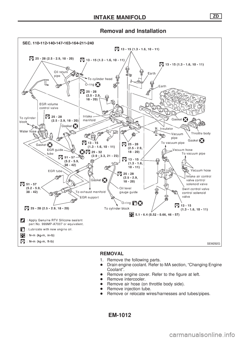
Removal and Installation
REMOVAL
1. Remove the following parts.
+Drain engine coolant. Refer to MA section, ªChanging Engine
Coolantº.
+Remove engine cover. Refer to the figure at left.
+Remove intercooler.
+Remove air hose (on throttle body side).
+Remove injection tube.
+Remove or relocate wires/harnesses and tubes/pipes.
SEM292G
INTAKE MANIFOLDZD
EM-1012
Page 752 of 1033
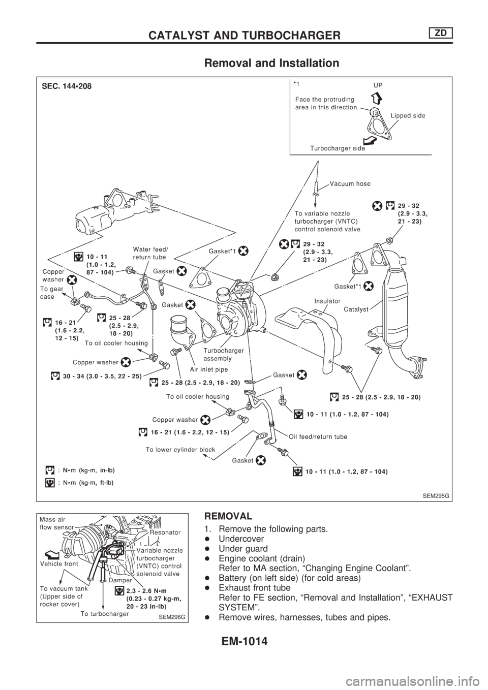
Removal and Installation
REMOVAL
1. Remove the following parts.
+Undercover
+Under guard
+Engine coolant (drain)
Refer to MA section, ªChanging Engine Coolantº.
+Battery (on left side) (for cold areas)
+Exhaust front tube
Refer to FE section, ªRemoval and Installationº, ªEXHAUST
SYSTEMº.
+Remove wires, harnesses, tubes and pipes.
SEM295G
SEM296G
CATALYST AND TURBOCHARGERZD
EM-1014
Page 758 of 1033
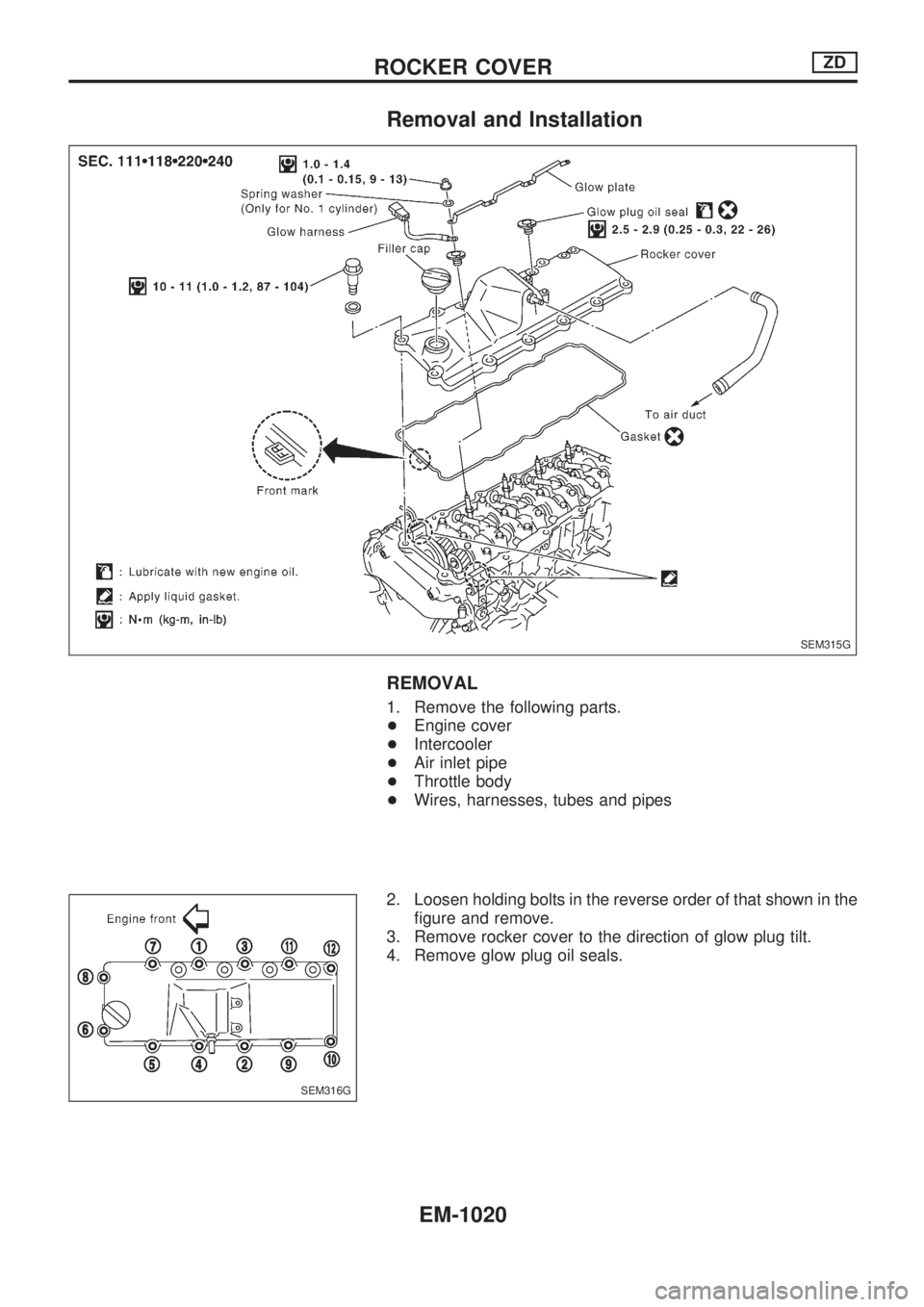
Removal and Installation
REMOVAL
1. Remove the following parts.
+Engine cover
+Intercooler
+Air inlet pipe
+Throttle body
+Wires, harnesses, tubes and pipes
2. Loosen holding bolts in the reverse order of that shown in the
figure and remove.
3. Remove rocker cover to the direction of glow plug tilt.
4. Remove glow plug oil seals.
SEM315G
SEM316G
ROCKER COVERZD
EM-1020
Page 766 of 1033
+Vacuum pipe
+Vacuum pump
2. Move the following parts.
+TDC sensor harness
+Power steering oil pump
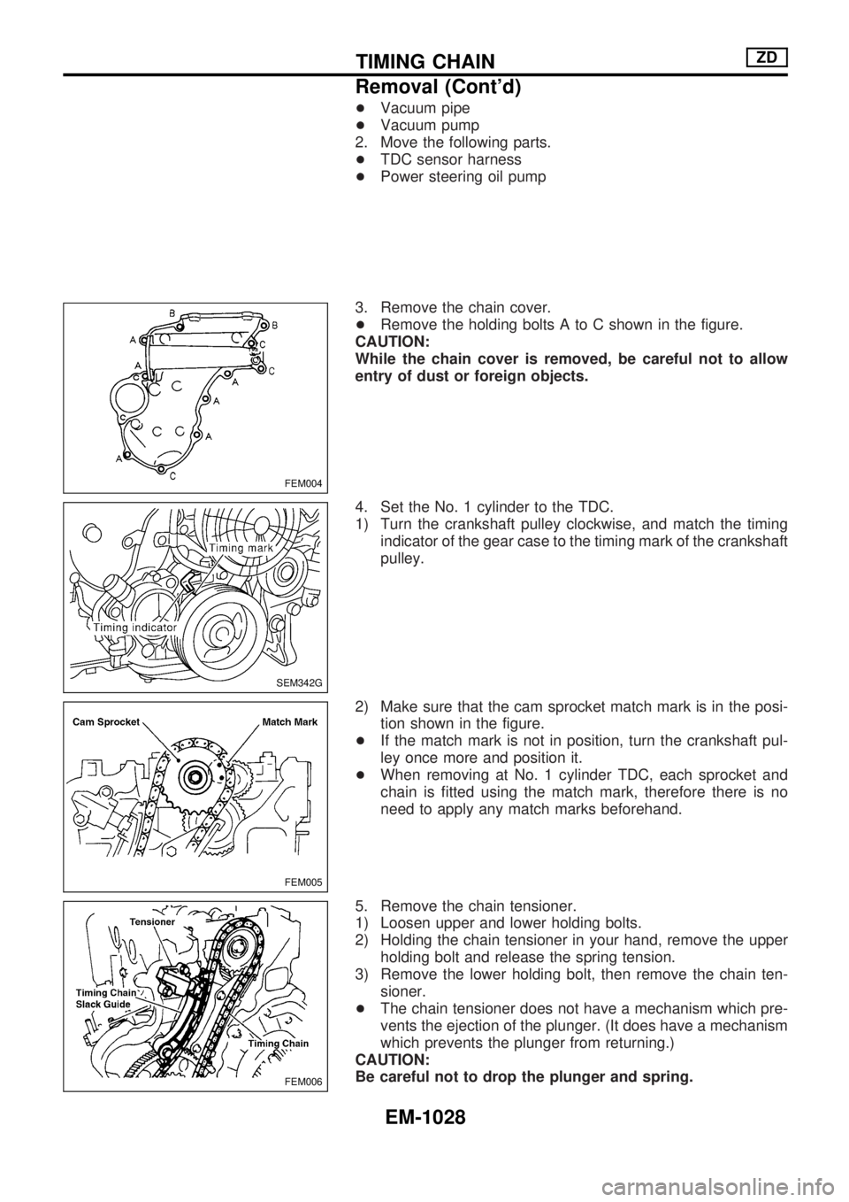
3. Remove the chain cover.
+Remove the holding bolts A to C shown in the figure.
CAUTION:
While the chain cover is removed, be careful not to allow
entry of dust or foreign objects.
4. Set the No. 1 cylinder to the TDC.
1) Turn the crankshaft pulley clockwise, and match the timing
indicator of the gear case to the timing mark of the crankshaft
pulley.
2) Make sure that the cam sprocket match mark is in the posi-
tion shown in the figure.
+If the match mark is not in position, turn the crankshaft pul-
ley once more and position it.
+When removing at No. 1 cylinder TDC, each sprocket and
chain is fitted using the match mark, therefore there is no
need to apply any match marks beforehand.
5. Remove the chain tensioner.
1) Loosen upper and lower holding bolts.
2) Holding the chain tensioner in your hand, remove the upper
holding bolt and release the spring tension.
3) Remove the lower holding bolt, then remove the chain ten-
sioner.
+The chain tensioner does not have a mechanism which pre-
vents the ejection of the plunger. (It does have a mechanism
which prevents the plunger from returning.)
CAUTION:
Be careful not to drop the plunger and spring.
FEM004
SEM342G
FEM005
FEM006
TIMING CHAINZD
Removal (Cont'd)
EM-1028
Page 768 of 1033
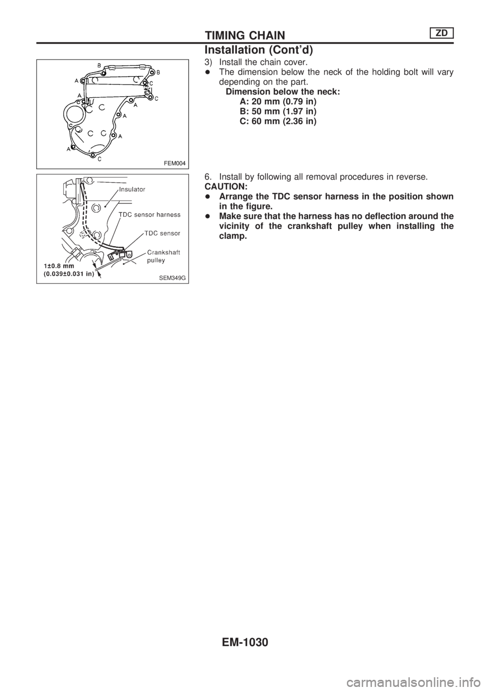
3) Install the chain cover.
+The dimension below the neck of the holding bolt will vary
depending on the part.
Dimension below the neck:
A: 20 mm (0.79 in)
B: 50 mm (1.97 in)
C: 60 mm (2.36 in)
6. Install by following all removal procedures in reverse.
CAUTION:
+Arrange the TDC sensor harness in the position shown
in the figure.
+Make sure that the harness has no deflection around the
vicinity of the crankshaft pulley when installing the
clamp.
FEM004
SEM349G
TIMING CHAINZD
Installation (Cont'd)
EM-1030
Page 787 of 1033
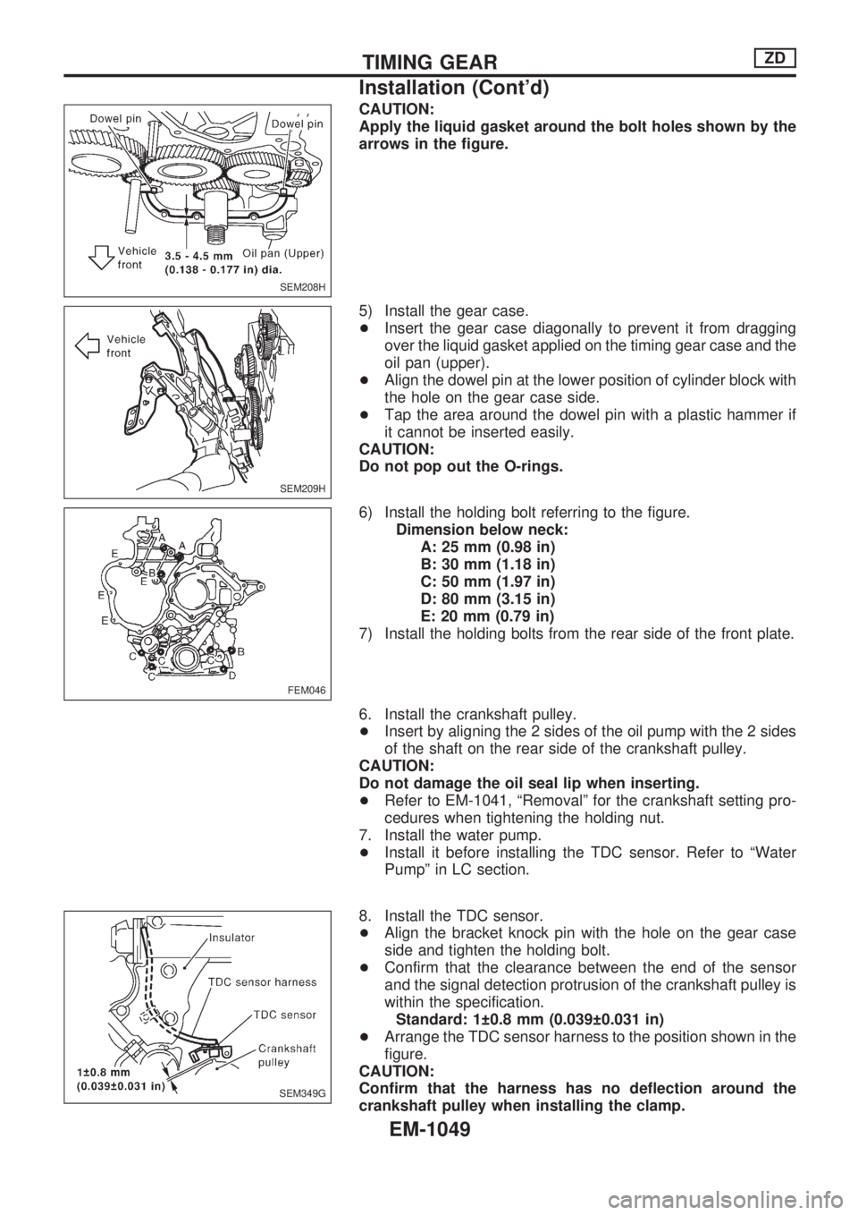
CAUTION:
Apply the liquid gasket around the bolt holes shown by the
arrows in the figure.
5) Install the gear case.
+Insert the gear case diagonally to prevent it from dragging
over the liquid gasket applied on the timing gear case and the
oil pan (upper).
+Align the dowel pin at the lower position of cylinder block with
the hole on the gear case side.
+Tap the area around the dowel pin with a plastic hammer if
it cannot be inserted easily.
CAUTION:
Do not pop out the O-rings.
6) Install the holding bolt referring to the figure.
Dimension below neck:
A: 25 mm (0.98 in)
B: 30 mm (1.18 in)
C: 50 mm (1.97 in)
D: 80 mm (3.15 in)
E: 20 mm (0.79 in)
7) Install the holding bolts from the rear side of the front plate.
6. Install the crankshaft pulley.
+Insert by aligning the 2 sides of the oil pump with the 2 sides
of the shaft on the rear side of the crankshaft pulley.
CAUTION:
Do not damage the oil seal lip when inserting.
+Refer to EM-1041, ªRemovalº for the crankshaft setting pro-
cedures when tightening the holding nut.
7. Install the water pump.
+Install it before installing the TDC sensor. Refer to ªWater
Pumpº in LC section.
8. Install the TDC sensor.
+Align the bracket knock pin with the hole on the gear case
side and tighten the holding bolt.
+Confirm that the clearance between the end of the sensor
and the signal detection protrusion of the crankshaft pulley is
within the specification.
Standard: 1 0.8 mm (0.039 0.031 in)
+Arrange the TDC sensor harness to the position shown in the
figure.
CAUTION:
Confirm that the harness has no deflection around the
crankshaft pulley when installing the clamp.
SEM208H
SEM209H
FEM046
SEM349G
TIMING GEARZD
Installation (Cont'd)
EM-1049
Page 803 of 1033
5. Disconnect harness connectors from alternator and air com-
pressor.
6. Remove alternator.
7. After removing refrigerant, remove pipes of air compressor
and inlet/outlet.
8. Disconnect heating hose, install blank cap to hose to prevent
coolant from leaking.
9. Remove heating pipe.
10. Remove heat insulator.
11. Remove catalytic converter.
Engine room (Right)
12. Remove power steering reservoir tank from bracket, and fix
it to the vehicle with a rope.
CAUTION:
Keep the reservoir tank level when fixing to prevent oil leak.
13. Remove fuel feed and return hoses.
CAUTION:
Install blank caps immediately to avoid fuel leakage.
14. Remove all harness connectors on the engine, and move
harnesses to the side of the vehicle.
Vehicle underfloor
15. Remove starter motor.
16. Detach A/T oil cooler pipes from oil pan. (A/T model)
17. Remove rear propeller shaft.
18. Remove mounting bolts to secure the engine to transmission.
1) Remove torque converter installation bolt. (A/T model)
2) Lift transmission bottom with transmission jack, and remove
rear mount members from the vehicle.
3) Lower transmission with the jack, and remove upper mount-
ing bolts securing the engine to transmission.
4) Lift transmission with the jack, and reinstall rear mount mem-
bers to the vehicle.
5) Position the jack to the front side of transmission.
6) Remove remaining mounting bolts securing the engine to
transmission.
Removal operation
19. Remove air conditioner high pressure pipes at the rear of the
engine room.
+This is due to some inconvenience in the rear slinger instal-
lation.
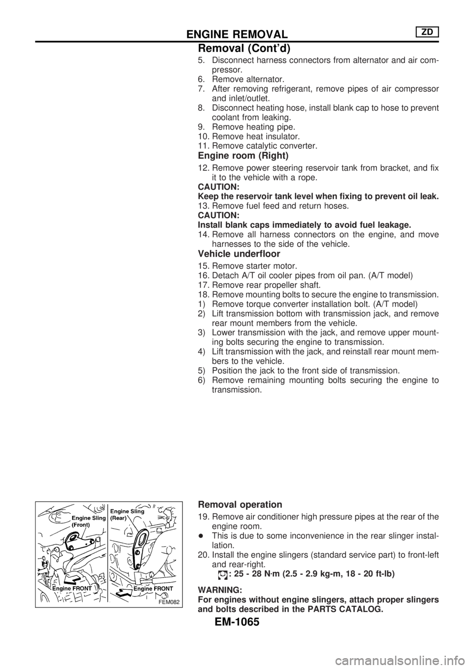
20. Install the engine slingers (standard service part) to front-left
and rear-right.
:25-28Nzm (2.5 - 2.9 kg-m, 18 - 20 ft-lb)
WARNING:
For engines without engine slingers, attach proper slingers
and bolts described in the PARTS CATALOG.
FEM082
ENGINE REMOVALZD
Removal (Cont'd)
EM-1065
Page 847 of 1033
Supplemental Restraint System (SRS) ªAIR
BAGº and ªSEAT BELT PRE-TENSIONERº
The Supplemental Restraint System such as ªAIR BAGº and ªSEAT BELT PRE-TENSIONERº used along
with a seat belt, helps to reduce the risk or severity of injury to the driver and front passenger for certain
types of collision. The SRS system composition which is available to NISSAN MODEL Y61 is as follows (The
composition varies according to the destination and optional equipment.):
+For a frontal collision
The Supplemental Restraint System consists of driver air bag module (located in the center of the
steering wheel), front passenger air bag module (located on the instrument panel on passenger side),
seat belt pre-tensioners, a diagnosis sensor unit, warning lamp, wiring harness and spiral cable.
+For a side collision
The Supplemental Restraint System consists of front side air bag module (located in the outer side of
front seat), satellite sensor, diagnosis sensor unit (one of components of air bags for a frontal collision),
wiring harness, warning lamp (one of components of air bags for a frontal collision).
Information necessary to service the system safely is included in theRS sectionof this Service Manual.
WARNING:
+To avoid rendering the SRS inoperative, which could increase the risk of personal injury or death
in the event of a collision which would result in air bag inflation, all maintenance should be per-
formed by an authorized NISSAN dealer.
+Improper maintenance, including incorrect removal and installation of the SRS, can lead to per-
sonal injury caused by unintentional activation of the system. For removal of Spiral Cable and
Air Bag Module, see the RS section.
+Do not use electrical test equipment on any circuit related to the SRS unless instructed to in this
Service Manual. Spiral cable and wiring harnesses covered with yellow insulation tape either just
before the harness connectors or for the complete harness are related to the SRS.
Precautions for Fuel
DIESEL ENGINE*:
Diesel fuel of at least 50 cetane for ZD30DDTi engine
* If two types of diesel fuel are available, use summer or win-
ter fuel properly according to the following temperature con-
ditions.
+Above þ7ÉC (20ÉF) ... Summer type diesel fuel.
+Below þ7ÉC (20ÉF) ... Winter type diesel fuel.
CAUTION:
+Do not use home heating oil, gasoline, or other alternate
fuels in your diesel engine. The use of those can cause
engine damage.
+Do not use summer fuel at temperature below þ7ÉC
(20ÉF). The cold temperature will cause wax to form in
the fuel. As a result, it may prevent the engine from run-
ning smoothly.
+Do not add gasoline or other alternate fuels to diesel
fuel.
PRECAUTIONS AND PREPARATION
GI-1002
Page 857 of 1033
Supplemental Restraint System (SRS) ªAIR
BAGº and ªSEAT BELT PRE-TENSIONERº
The Supplemental Restraint System such as ªAIR BAGº and ªSEAT BELT PRE-TENSIONERº used along
with a seat belt, helps to reduce the risk or severity of injury to the driver and front passenger for certain
types of collision. The SRS system composition which is available to NISSAN MODEL Y61 is as follows (The
composition varies according to the destination and optional equipment.):
+For a frontal collision
The Supplemental Restraint System consists of driver air bag module (located in the center of the
steering wheel), front passenger air bag module (located on the instrument panel on passenger side),
seat belt pre-tensioners, a diagnosis sensor unit, warning lamp, wiring harness and spiral cable.
+For a side collision
The Supplemental Restraint System consists of front side air bag module (located in the outer side of
front seat), satellite sensor, diagnosis sensor unit (one of components of air bags for a frontal collision),
wiring harness, warning lamp (one of components of air bags for a frontal collision).
Information necessary to service the system safely is included in theRS sectionof this Service Manual.
WARNING:
+To avoid rendering the SRS inoperative, which could increase the risk of personal injury or death
in the event of a collision which would result in air bag inflation, all maintenance should be per-
formed by an authorized NISSAN dealer.
+Improper maintenance, including incorrect removal and installation of the SRS, can lead to per-
sonal injury caused by unintentional activation of the system. For removal of Spiral Cable and
Air Bag Module, see the RS section.
+Do not use electrical test equipment on any circuit related to the SRS unless instructed to in this
Service Manual. Spiral cable and wiring harnesses covered with yellow insulation tape either just
before the harness connectors or for the complete harness are related to the SRS.
Precautions for Refrigerant Connection
A new type refrigerant connection has been introduced to all refrigerant lines except the following location.
+Expansion valve to cooling unit
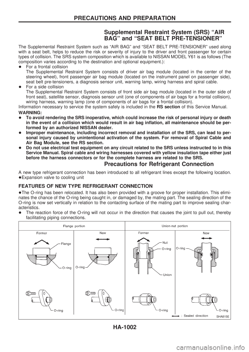
FEATURES OF NEW TYPE REFRIGERANT CONNECTION
+The O-ring has been relocated. It has also been provided with a groove for proper installation. This elimi-
nates the chance of the O-ring being caught in, or damaged by, the mating part. The sealing direction of the
O-ring is now set vertically in relation to the contacting surface of the mating part to improve sealing char-
acteristics.
+The reaction force of the O-ring will not occur in the direction that causes the joint to pull out, thereby
facilitating piping connections.
SHA815E
PRECAUTIONS AND PREPARATION
HA-1002
Page 881 of 1033
Engine coolant temperature sensor
(ECTS) .............................................. EC-1092
Engine oil filter replacement ................. MA-1013
Engine oil replacement ......................... MA-1012
Engine removal ..................................... EM-1064
Engine serial number ............................. GI-1008
F
F/FOG - Wiring diagram ........................ EL-1052
Final drive disassembly .............. PD-1004, 1005
Fluid temperature sensor (A/T) ............. AT-1081
Fluids .................................................... MA-1008
Flywheel runout .................................... EM-1095
Fog lamp, front ...................................... EL-1052
Fog lamp, rear ....................................... EL-1053
Forward clutch ....................................... AT-1167
Front axle .............................................. FA-1002
Front final drive disassembly (4WD) .... PD-1004
Front fog lamp ....................................... EL-1052
Front passenger air bag ....................... RS-1003
Front seat .............................................. BT-1006
Front washer .......................................... EL-1098
Front wiper ............................................. EL-1098
Fuel cut control (at no load & high
engine speed) ................................... EC-1021
Fuel filter replacement .......................... MA-1017
Fuel gauge ............................................. EL-1073
Fuel injection system ............................ EC-1019
Fuel line inspection ............................... MA-1018
Fuel precautions ..................................... GI-1002
Fuse block ............................................. EL-1229
Fuse ....................................................... EL-1230
Fusible link ............................................. EL-1230
G
GLOW - Wiring diagram ....................... EC-1221
Gauges .................................................. EL-1073
Glow plug .............................................. EC-1221
Glow relay ............................................. EC-1221
Grease ........................................ MA-1008, 1016
Ground distribution ................................ EL-1013
H
HEAT UP - Wiring diagram .................. EC-1242
HEATER - Wiring diagram .................... HA-1005
HLC - Wiring diagram ............................ EL-1099
HORN - Wiring diagram ........................ EL-1100
Harness layout ....................................... EL-1191
Hazard warning lamp ............................ EL-1058
Headlamp washer .................................. EL-1099
Headlamp wiper ..................................... EL-1099
Headlamp .............................................. EL-1044
Heat up switch ...................................... EC-1241
High clutch ............................................. AT-1165Horn ....................................................... EL-1100
How to erase DTC for OBD system ..... EC-1032
I
ILL - Wiring diagram .............................. EL-1061
Identification plate .................................. GI-1008
Idle speed ............................................. EC-1049
Illumination ............................................. EL-1060
Injection nozzle ..................................... EC-1023
Intake manifold ..................................... EM-1012
Interior lamp ........................................... EL-1067
Interior ................................................... BT-1004
J
Junction box (J/B) .................................. EL-1229
L
License lamp ......................................... EL-1046
Lifting points ........................................... GI-1009
Line pressure solenoid valve ................ AT-1086
Line pressure test (A/T) ........................ AT-1044
Liquid gasket application ...................... EM-1003
Location of electrical units ..................... EL-1185
Low and reverse brake ......................... AT-1171
Lubricants ............................................. MA-1008
Luggage room lamp .............................. EL-1067
M
MAFS - Wiring diagram ........................ EC-1086
MAIN - Wiring diagram ......................... EC-1077
MAJOR OVERHALL .............................. AT-1129
METER - Wiring diagram ...................... EL-1073
Maintenance (engine) ........................... MA-1011
Malfunction indicator lamp (MIL) .......... EC-1033
Manifold tightening torque (intake &
exhaust) ............................................ MA-1011
Mass air flow sensor (MAFS) ............... EC-1086
Meter ...................................................... EL-1073
Mirror, door ............................................ BT-1007
Mirror, outside ....................................... BT-1007
Model variation ....................................... GI-1005
N
NATS (Nissan Anti-theft System) .......... EL-1163
NATS - Wiring diagram ......................... EL-1166
NVH troubleshooting (EM) ................... EM-1008
ALPHABETICAL INDEX
IDX-1003