clutch NISSAN PATROL 2000 Electronic Repair Manual
[x] Cancel search | Manufacturer: NISSAN, Model Year: 2000, Model line: PATROL, Model: NISSAN PATROL 2000Pages: 1033, PDF Size: 30.71 MB
Page 1 of 1033
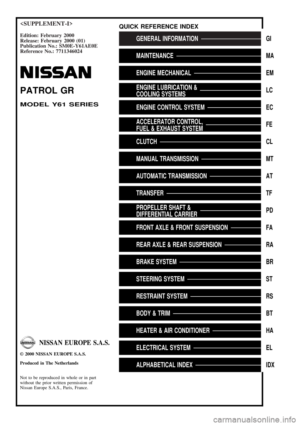
Edition: February 2000
Release: February 2000 (01)
Publication No.: SM0E-Y61AE0E
Reference No.: 7711346024GENERAL INFORMATIONGI
MAINTENANCEMA
ENGINE MECHANICALEM
ENGINE LUBRICATION &
COOLING SYSTEMSLC
ENGINE CONTROL SYSTEMEC
ACCELERATOR CONTROL,
FUEL & EXHAUST SYSTEMFE
CLUTCHCL
MANUAL TRANSMISSIONMT
AUTOMATIC TRANSMISSIONAT
TRANSFERTF
PROPELLER SHAFT &
DIFFERENTIAL CARRIERPD
FRONT AXLE & FRONT SUSPENSIONFA
REAR AXLE & REAR SUSPENSIONRA
BRAKE SYSTEMBR
STEERING SYSTEMST
RESTRAINT SYSTEMRS
BODY & TRIMBT
HEATER & AIR CONDITIONERHA
ELECTRICAL SYSTEMEL
ALPHABETICAL INDEXIDX
PATROL GR
MODEL Y61 SERIES
NISSAN EUROPE S.A.S.
2000 NISSAN EUROPE S.A.S.
Produced in The Netherlands
Not to be reproduced in whole or in part
without the prior written permission of
Nissan Europe S.A.S., Paris, France.
QUICK REFERENCE INDEX
Page 3 of 1033
AUTOMATIC TRANSMISSION
SECTION
AT
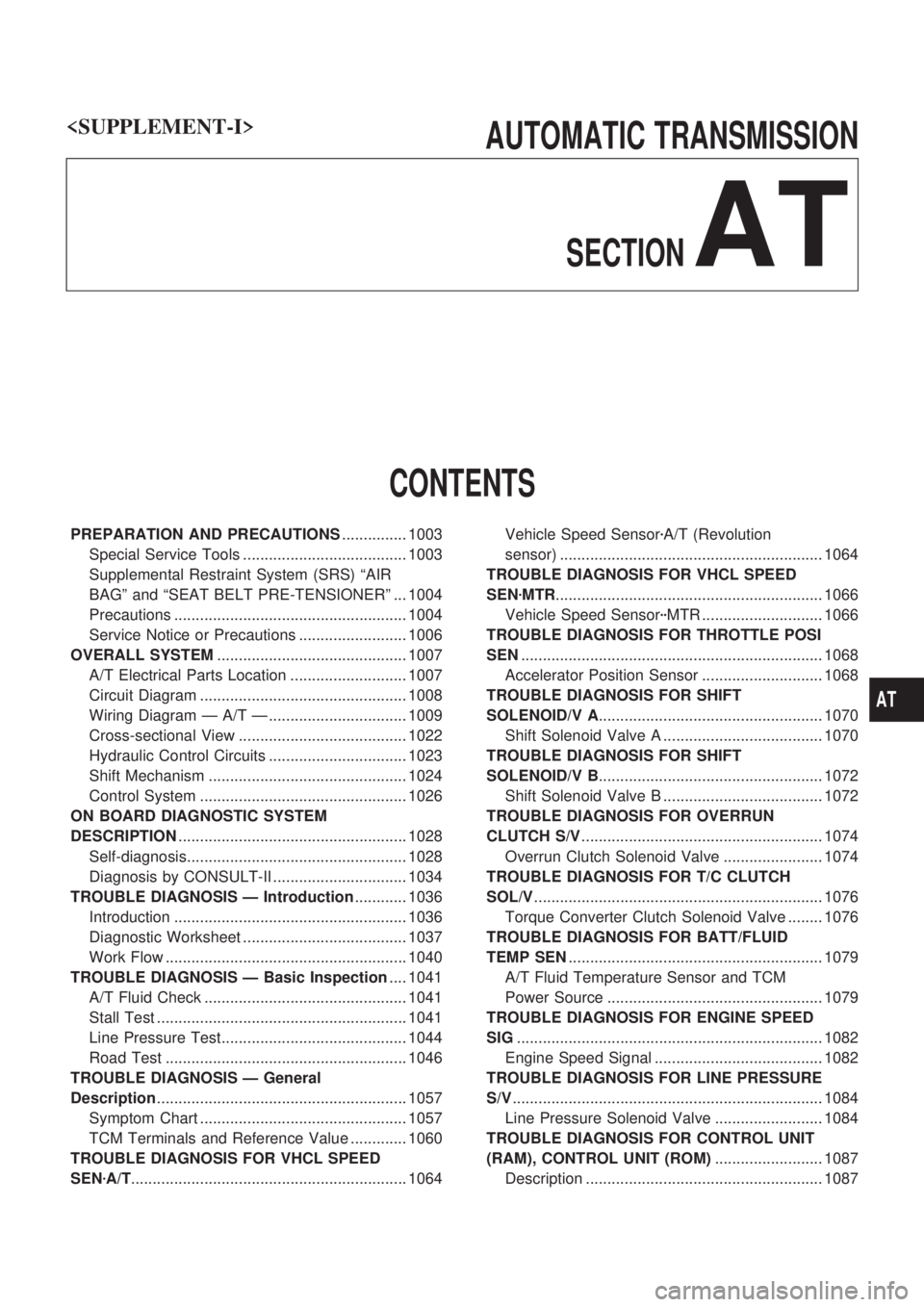
CONTENTS
PREPARATION AND PRECAUTIONS............... 1003
Special Service Tools ...................................... 1003
Supplemental Restraint System (SRS) ªAIR
BAGº and ªSEAT BELT PRE-TENSIONERº ... 1004
Precautions ...................................................... 1004
Service Notice or Precautions ......................... 1006
OVERALL SYSTEM............................................ 1007
A/T Electrical Parts Location ........................... 1007
Circuit Diagram ................................................ 1008
Wiring Diagram Ð A/T Ð ................................ 1009
Cross-sectional View ....................................... 1022
Hydraulic Control Circuits ................................ 1023
Shift Mechanism .............................................. 1024
Control System ................................................ 1026
ON BOARD DIAGNOSTIC SYSTEM
DESCRIPTION..................................................... 1028
Self-diagnosis................................................... 1028
Diagnosis by CONSULT-II ............................... 1034
TROUBLE DIAGNOSIS Ð Introduction............ 1036
Introduction ...................................................... 1036
Diagnostic Worksheet ...................................... 1037
Work Flow ........................................................ 1040
TROUBLE DIAGNOSIS Ð Basic Inspection.... 1041
A/T Fluid Check ............................................... 1041
Stall Test .......................................................... 1041
Line Pressure Test........................................... 1044
Road Test ........................................................ 1046
TROUBLE DIAGNOSIS Ð General
Description.......................................................... 1057
Symptom Chart ................................................ 1057
TCM Terminals and Reference Value ............. 1060
TROUBLE DIAGNOSIS FOR VHCL SPEED
SENzA/T................................................................ 1064Vehicle Speed SensorzA/T (Revolution
sensor) ............................................................. 1064
TROUBLE DIAGNOSIS FOR VHCL SPEED
SENzMTR.............................................................. 1066
Vehicle Speed SensorzzMTR ............................ 1066
TROUBLE DIAGNOSIS FOR THROTTLE POSI
SEN...................................................................... 1068
Accelerator Position Sensor ............................ 1068
TROUBLE DIAGNOSIS FOR SHIFT
SOLENOID/V A.................................................... 1070
Shift Solenoid Valve A ..................................... 1070
TROUBLE DIAGNOSIS FOR SHIFT
SOLENOID/V B.................................................... 1072
Shift Solenoid Valve B ..................................... 1072
TROUBLE DIAGNOSIS FOR OVERRUN
CLUTCH S/V........................................................ 1074
Overrun Clutch Solenoid Valve ....................... 1074
TROUBLE DIAGNOSIS FOR T/C CLUTCH
SOL/V................................................................... 1076
Torque Converter Clutch Solenoid Valve ........ 1076
TROUBLE DIAGNOSIS FOR BATT/FLUID
TEMP SEN........................................................... 1079
A/T Fluid Temperature Sensor and TCM
Power Source .................................................. 1079
TROUBLE DIAGNOSIS FOR ENGINE SPEED
SIG....................................................................... 1082
Engine Speed Signal ....................................... 1082
TROUBLE DIAGNOSIS FOR LINE PRESSURE
S/V........................................................................ 1084
Line Pressure Solenoid Valve ......................... 1084
TROUBLE DIAGNOSIS FOR CONTROL UNIT
(RAM), CONTROL UNIT (ROM)......................... 1087
Description ....................................................... 1087
AT
Page 4 of 1033
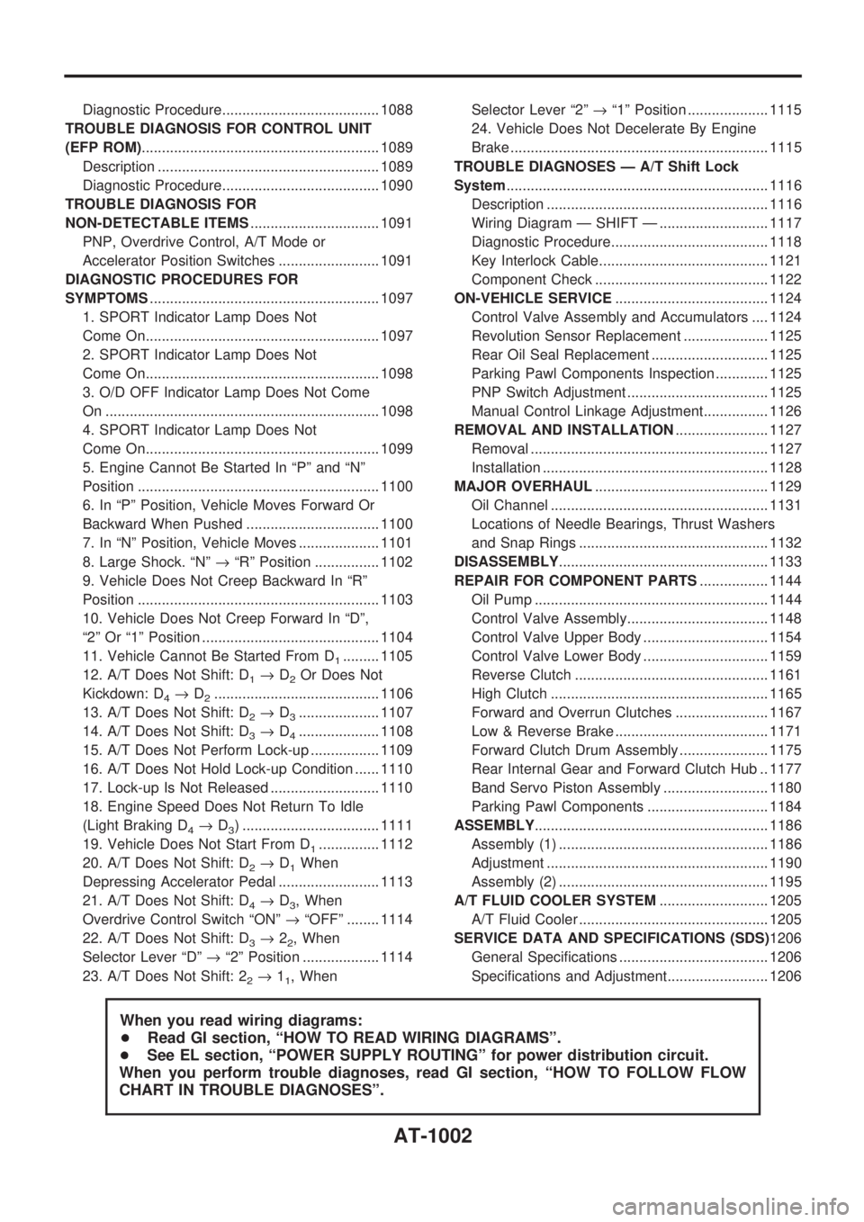
Diagnostic Procedure....................................... 1088
TROUBLE DIAGNOSIS FOR CONTROL UNIT
(EFP ROM)........................................................... 1089
Description ....................................................... 1089
Diagnostic Procedure....................................... 1090
TROUBLE DIAGNOSIS FOR
NON-DETECTABLE ITEMS................................ 1091
PNP, Overdrive Control, A/T Mode or
Accelerator Position Switches ......................... 1091
DIAGNOSTIC PROCEDURES FOR
SYMPTOMS......................................................... 1097
1. SPORT Indicator Lamp Does Not
Come On.......................................................... 1097
2. SPORT Indicator Lamp Does Not
Come On.......................................................... 1098
3. O/D OFF Indicator Lamp Does Not Come
On .................................................................... 1098
4. SPORT Indicator Lamp Does Not
Come On.......................................................... 1099
5. Engine Cannot Be Started In ªPº and ªNº
Position ............................................................ 1100
6. In ªPº Position, Vehicle Moves Forward Or
Backward When Pushed ................................. 1100
7. In ªNº Position, Vehicle Moves .................... 1101
8. Large Shock. ªNº®ªRº Position ................ 1102
9. Vehicle Does Not Creep Backward In ªRº
Position ............................................................ 1103
10. Vehicle Does Not Creep Forward In ªDº,
ª2º Or ª1º Position ............................................ 1104
11. Vehicle Cannot Be Started From D
1......... 1105
12. A/T Does Not Shift: D
1®D2Or Does Not
Kickdown: D
4®D2......................................... 1106
13. A/T Does Not Shift: D
2®D3.................... 1107
14. A/T Does Not Shift: D
3®D4.................... 1108
15. A/T Does Not Perform Lock-up ................. 1109
16. A/T Does Not Hold Lock-up Condition ...... 1110
17. Lock-up Is Not Released ........................... 1110
18. Engine Speed Does Not Return To Idle
(Light Braking D
4®D3) .................................. 1111
19. Vehicle Does Not Start From D
1............... 1112
20. A/T Does Not Shift: D
2®D1When
Depressing Accelerator Pedal ......................... 1113
21. A/T Does Not Shift: D
4®D3, When
Overdrive Control Switch ªONº®ªOFFº ........ 1114
22. A/T Does Not Shift: D
3®22, When
Selector Lever ªDº®ª2º Position ................... 1114
23. A/T Does Not Shift: 2
2®11, WhenSelector Lever ª2º®ª1º Position .................... 1115
24. Vehicle Does Not Decelerate By Engine
Brake ................................................................ 1115
TROUBLE DIAGNOSES Ð A/T Shift Lock
System................................................................. 1116
Description ....................................................... 1116
Wiring Diagram Ð SHIFT Ð ........................... 1117
Diagnostic Procedure....................................... 1118
Key Interlock Cable.......................................... 1121
Component Check ........................................... 1122
ON-VEHICLE SERVICE...................................... 1124
Control Valve Assembly and Accumulators .... 1124
Revolution Sensor Replacement ..................... 1125
Rear Oil Seal Replacement ............................. 1125
Parking Pawl Components Inspection ............. 1125
PNP Switch Adjustment ................................... 1125
Manual Control Linkage Adjustment................ 1126
REMOVAL AND INSTALLATION....................... 1127
Removal ........................................................... 1127
Installation ........................................................ 1128
MAJOR OVERHAUL........................................... 1129
Oil Channel ...................................................... 1131
Locations of Needle Bearings, Thrust Washers
and Snap Rings ............................................... 1132
DISASSEMBLY.................................................... 1133
REPAIR FOR COMPONENT PARTS................. 1144
Oil Pump .......................................................... 1144
Control Valve Assembly................................... 1148
Control Valve Upper Body ............................... 1154
Control Valve Lower Body ............................... 1159
Reverse Clutch ................................................ 1161
High Clutch ...................................................... 1165
Forward and Overrun Clutches ....................... 1167
Low & Reverse Brake ...................................... 1171
Forward Clutch Drum Assembly ...................... 1175
Rear Internal Gear and Forward Clutch Hub .. 1177
Band Servo Piston Assembly .......................... 1180
Parking Pawl Components .............................. 1184
ASSEMBLY.......................................................... 1186
Assembly (1) .................................................... 1186
Adjustment ....................................................... 1190
Assembly (2) .................................................... 1195
A/T FLUID COOLER SYSTEM........................... 1205
A/T Fluid Cooler ............................................... 1205
SERVICE DATA AND SPECIFICATIONS (SDS)1206
General Specifications ..................................... 1206
Specifications and Adjustment......................... 1206
When you read wiring diagrams:
+Read GI section, ªHOW TO READ WIRING DIAGRAMSº.
+See EL section, ªPOWER SUPPLY ROUTINGº for power distribution circuit.
When you perform trouble diagnoses, read GI section, ªHOW TO FOLLOW FLOW
CHART IN TROUBLE DIAGNOSESº.
AT-1002
Page 5 of 1033
Special Service Tools
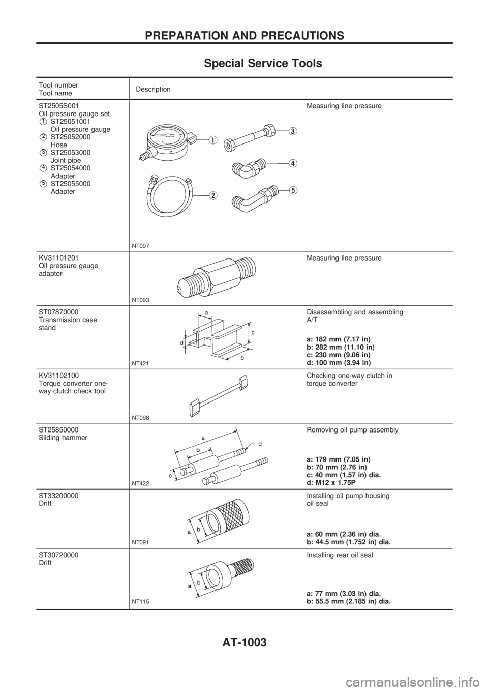
Tool number
Tool nameDescription
ST2505S001
Oil pressure gauge set
V1ST25051001
Oil pressure gauge
V2ST25052000
Hose
V3ST25053000
Joint pipe
V4ST25054000
Adapter
V5ST25055000
Adapter
NT097
Measuring line pressure
KV31101201
Oil pressure gauge
adapter
NT093
Measuring line pressure
ST07870000
Transmission case
stand
NT421
Disassembling and assembling
A/T
a: 182 mm (7.17 in)
b: 282 mm (11.10 in)
c: 230 mm (9.06 in)
d: 100 mm (3.94 in)
KV31102100
Torque converter one-
way clutch check tool
NT098
Checking one-way clutch in
torque converter
ST25850000
Sliding hammer
NT422
Removing oil pump assembly
a: 179 mm (7.05 in)
b: 70 mm (2.76 in)
c: 40 mm (1.57 in) dia.
d: M12 x 1.75P
ST33200000
Drift
NT091
Installing oil pump housing
oil seal
a: 60 mm (2.36 in) dia.
b: 44.5 mm (1.752 in) dia.
ST30720000
Drift
NT115
Installing rear oil seal
a: 77 mm (3.03 in) dia.
b: 55.5 mm (2.185 in) dia.
PREPARATION AND PRECAUTIONS
AT-1003
Page 6 of 1033
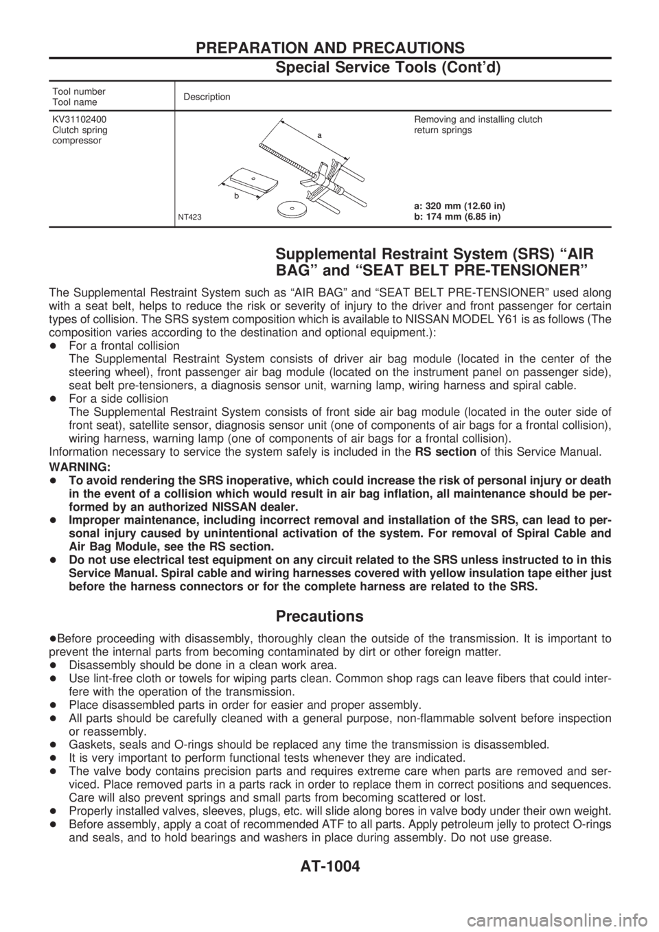
Tool number
Tool nameDescription
KV31102400
Clutch spring
compressor
NT423
Removing and installing clutch
return springs
a: 320 mm (12.60 in)
b: 174 mm (6.85 in)
Supplemental Restraint System (SRS) ªAIR
BAGº and ªSEAT BELT PRE-TENSIONERº
The Supplemental Restraint System such as ªAIR BAGº and ªSEAT BELT PRE-TENSIONERº used along
with a seat belt, helps to reduce the risk or severity of injury to the driver and front passenger for certain
types of collision. The SRS system composition which is available to NISSAN MODEL Y61 is as follows (The
composition varies according to the destination and optional equipment.):
+For a frontal collision
The Supplemental Restraint System consists of driver air bag module (located in the center of the
steering wheel), front passenger air bag module (located on the instrument panel on passenger side),
seat belt pre-tensioners, a diagnosis sensor unit, warning lamp, wiring harness and spiral cable.
+For a side collision
The Supplemental Restraint System consists of front side air bag module (located in the outer side of
front seat), satellite sensor, diagnosis sensor unit (one of components of air bags for a frontal collision),
wiring harness, warning lamp (one of components of air bags for a frontal collision).
Information necessary to service the system safely is included in theRS sectionof this Service Manual.
WARNING:
+To avoid rendering the SRS inoperative, which could increase the risk of personal injury or death
in the event of a collision which would result in air bag inflation, all maintenance should be per-
formed by an authorized NISSAN dealer.
+Improper maintenance, including incorrect removal and installation of the SRS, can lead to per-
sonal injury caused by unintentional activation of the system. For removal of Spiral Cable and
Air Bag Module, see the RS section.
+Do not use electrical test equipment on any circuit related to the SRS unless instructed to in this
Service Manual. Spiral cable and wiring harnesses covered with yellow insulation tape either just
before the harness connectors or for the complete harness are related to the SRS.
Precautions
+Before proceeding with disassembly, thoroughly clean the outside of the transmission. It is important to
prevent the internal parts from becoming contaminated by dirt or other foreign matter.
+Disassembly should be done in a clean work area.
+Use lint-free cloth or towels for wiping parts clean. Common shop rags can leave fibers that could inter-
fere with the operation of the transmission.
+Place disassembled parts in order for easier and proper assembly.
+All parts should be carefully cleaned with a general purpose, non-flammable solvent before inspection
or reassembly.
+Gaskets, seals and O-rings should be replaced any time the transmission is disassembled.
+It is very important to perform functional tests whenever they are indicated.
+The valve body contains precision parts and requires extreme care when parts are removed and ser-
viced. Place removed parts in a parts rack in order to replace them in correct positions and sequences.
Care will also prevent springs and small parts from becoming scattered or lost.
+Properly installed valves, sleeves, plugs, etc. will slide along bores in valve body under their own weight.
+Before assembly, apply a coat of recommended ATF to all parts. Apply petroleum jelly to protect O-rings
and seals, and to hold bearings and washers in place during assembly. Do not use grease.
PREPARATION AND PRECAUTIONS
Special Service Tools (Cont'd)
AT-1004
Page 26 of 1033
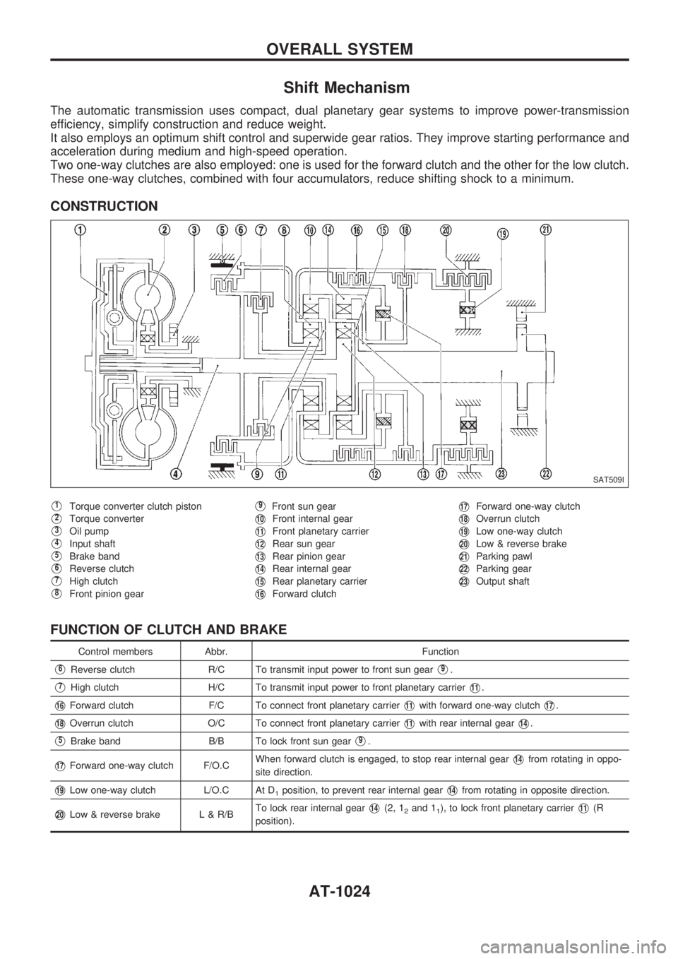
Shift Mechanism
The automatic transmission uses compact, dual planetary gear systems to improve power-transmission
efficiency, simplify construction and reduce weight.
It also employs an optimum shift control and superwide gear ratios. They improve starting performance and
acceleration during medium and high-speed operation.
Two one-way clutches are also employed: one is used for the forward clutch and the other for the low clutch.
These one-way clutches, combined with four accumulators, reduce shifting shock to a minimum.
CONSTRUCTION
V1Torque converter clutch piston
V2Torque converter
V3Oil pump
V4Input shaft
V5Brake band
V6Reverse clutch
V7High clutch
V8Front pinion gear
V9Front sun gear
V10Front internal gear
V11Front planetary carrier
V12Rear sun gear
V13Rear pinion gear
V14Rear internal gear
V15Rear planetary carrier
V16Forward clutch
V17Forward one-way clutch
V18Overrun clutch
V19Low one-way clutch
V20Low & reverse brake
V21Parking pawl
V22Parking gear
V23Output shaft
FUNCTION OF CLUTCH AND BRAKE
Control members Abbr. Function
V6Reverse clutch R/C To transmit input power to front sun gearV9.
V7High clutch H/C To transmit input power to front planetary carrierV11.
V16Forward clutch F/C To connect front planetary carrierV11with forward one-way clutchV17.
V18Overrun clutch O/C To connect front planetary carrierV11with rear internal gearV14.
V5Brake band B/B To lock front sun gearV9.
V17Forward one-way clutch F/O.CWhen forward clutch is engaged, to stop rear internal gearV14from rotating in oppo-
site direction.
V19Low one-way clutch L/O.C At D1position, to prevent rear internal gearV14from rotating in opposite direction.
V20Low & reverse brake L & R/BTo lock rear internal gearV14(2, 12and 11), to lock front planetary carrierV11(R
position).
SAT509I
OVERALL SYSTEM
AT-1024
Page 27 of 1033
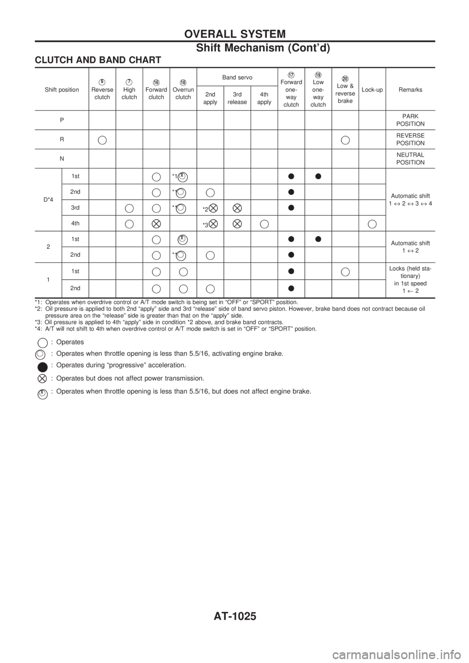
CLUTCH AND BAND CHART
Shift positionV6
Reverse
clutchV7
High
clutchV16Forward
clutchV18Overrun
clutchBand servo
V17Forward
one-
way
clutchV19Low
one-
way
clutchV20Low &
reverse
brakeLock-up Remarks
2nd
apply3rd
release4th
apply
PPARK
POSITION
R
jjREVERSE
POSITION
NNEUTRAL
POSITION
D*41st
j*1jVX++
Automatic shift
1«2«3«4 2ndj*1jVj+
3rdjj*1jV*2^^+
4thj^*3^^jj
21stjjVX++Automatic shift
1«2
2nd
j*1jVj+
11stjj+jLocks (held sta-
tionary)
in 1st speed
1¬2 2nd
jjj+
*1: Operates when overdrive control or A/T mode switch is being set in ªOFFº or ªSPORTº position.
*2: Oil pressure is applied to both 2nd ªapplyº side and 3rd ªreleaseº side of band servo piston. However, brake band does not contract because oil
pressure area on the ªreleaseº side is greater than that on the ªapplyº side.
*3: Oil pressure is applied to 4th ªapplyº side in condition *2 above, and brake band contracts.
*4: A/T will not shift to 4th when overdrive control or A/T mode switch is set in ªOFFº or ªSPORTº position.
j: Operates
: Operates when throttle opening is less than 5.5/16, activating engine brake.
*: Operates during ªprogressiveº acceleration.
^: Operates but does not affect power transmission.
jVX: Operates when throttle opening is less than 5.5/16, but does not affect engine brake.
jV
OVERALL SYSTEM
Shift Mechanism (Cont'd)
AT-1025
Page 28 of 1033
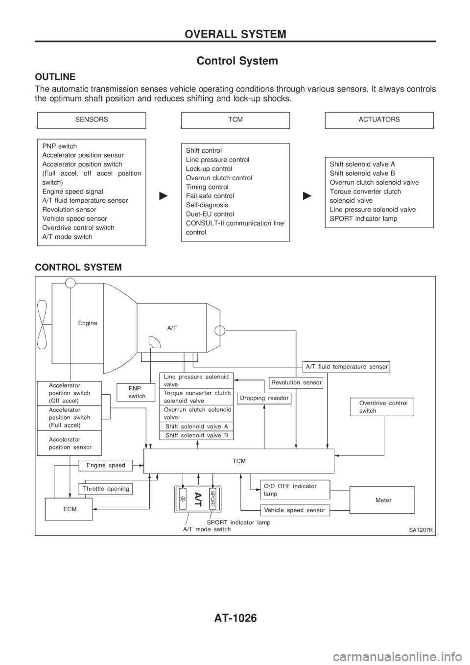
Control System
OUTLINE
The automatic transmission senses vehicle operating conditions through various sensors. It always controls
the optimum shaft position and reduces shifting and lock-up shocks.
SENSORSTCMACTUATORS
PNP switch
Accelerator position sensor
Accelerator position switch
(Full accel, off accel position
switch)
Engine speed signal
A/T fluid temperature sensor
Revolution sensor
Vehicle speed sensor
Overdrive control switch
A/T mode switch
c
Shift control
Line pressure control
Lock-up control
Overrun clutch control
Timing control
Fail-safe control
Self-diagnosis
Duet-EU control
CONSULT-II communication line
control
c
Shift solenoid valve A
Shift solenoid valve B
Overrun clutch solenoid valve
Torque converter clutch
solenoid valve
Line pressure solenoid valve
SPORT indicator lamp
CONTROL SYSTEM
SAT207K
OVERALL SYSTEM
AT-1026
Page 29 of 1033
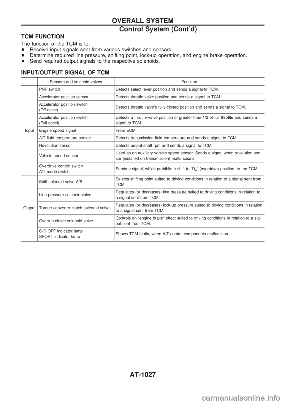
TCM FUNCTION
The function of the TCM is to:
+Receive input signals sent from various switches and sensors.
+Determine required line pressure, shifting point, lock-up operation, and engine brake operation.
+Send required output signals to the respective solenoids.
INPUT/OUTPUT SIGNAL OF TCM
Sensors and solenoid valves Function
InputPNP switch Detects select lever position and sends a signal to TCM.
Accelerator position sensor Detects throttle valve position and sends a signal to TCM.
Accelerator position switch
(Off accel)Detects throttle valve's fully-closed position and sends a signal to TCM.
Accelerator position switch
(Full accel)Detects a throttle valve position of greater than 1/2 of full throttle and sends a
signal to TCM.
Engine speed signal From ECM.
A/T fluid temperature sensor Detects transmission fluid temperature and sends a signal to TCM.
Revolution sensor Detects output shaft rpm and sends a signal to TCM.
Vehicle speed sensorUsed as an auxiliary vehicle speed sensor. Sends a signal when revolution sen-
sor (installed on transmission) malfunctions.
Overdrive control switch
A/T mode switchSends a signal, which prohibits a shift to ªD
4º (overdrive) position, to the TCM.
OutputShift solenoid valve A/BSelects shifting point suited to driving conditions in relation to a signal sent from
TCM.
Line pressure solenoid valveRegulates (or decreases) line pressure suited to driving conditions in relation to
a signal sent from TCM.
Torque converter clutch solenoid valveRegulates (or decreases) lock-up pressure suited to driving conditions in relation
to a signal sent from TCM.
Overrun clutch solenoid valveControls an ªengine brakeº effect suited to driving conditions in relation to a sig-
nal sent from TCM.
O/D OFF indicator lamp
SPORT indicator lampShows TCM faults, when A/T control components malfunction.
OVERALL SYSTEM
Control System (Cont'd)
AT-1027
Page 30 of 1033
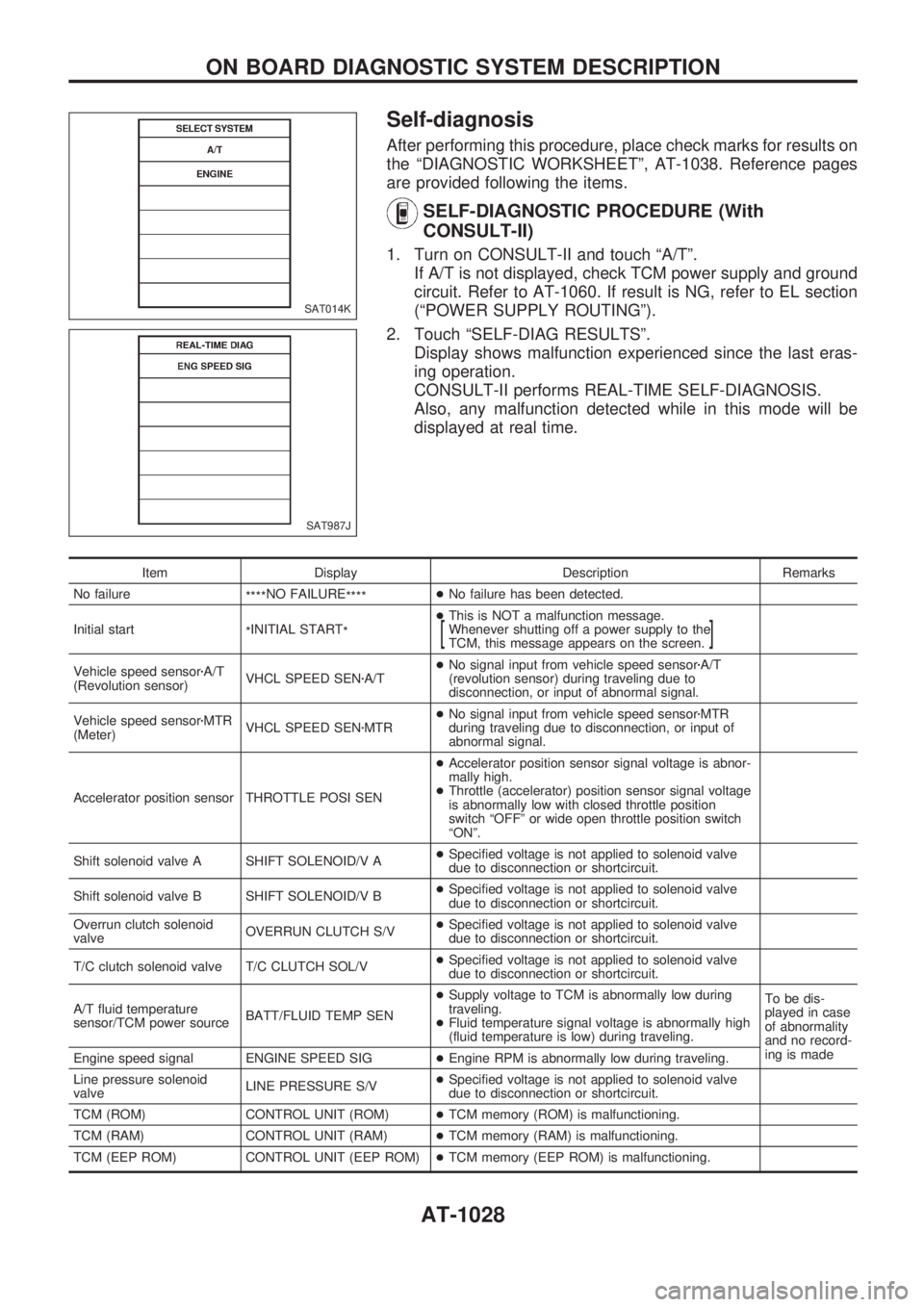
Self-diagnosis
After performing this procedure, place check marks for results on
the ªDIAGNOSTIC WORKSHEETº, AT-1038. Reference pages
are provided following the items.
SELF-DIAGNOSTIC PROCEDURE (With
CONSULT-II)
1. Turn on CONSULT-II and touch ªA/Tº.
If A/T is not displayed, check TCM power supply and ground
circuit. Refer to AT-1060. If result is NG, refer to EL section
(ªPOWER SUPPLY ROUTINGº).
2. Touch ªSELF-DIAG RESULTSº.
Display shows malfunction experienced since the last eras-
ing operation.
CONSULT-II performs REAL-TIME SELF-DIAGNOSIS.
Also, any malfunction detected while in this mode will be
displayed at real time.
Item Display Description Remarks
No failure
****NO FAILURE
****+No failure has been detected.
Initial start
*INITIAL START
*+This is NOT a malfunction message.
Whenever shutting off a power supply to the
TCM, this message appears on the screen.
[]
Vehicle speed sensorzA/T
(Revolution sensor)VHCL SPEED SENzA/T+No signal input from vehicle speed sensorzA/T
(revolution sensor) during traveling due to
disconnection, or input of abnormal signal.
Vehicle speed sensorzMTR
(Meter)VHCL SPEED SENzMTR+No signal input from vehicle speed sensorzMTR
during traveling due to disconnection, or input of
abnormal signal.
Accelerator position sensor THROTTLE POSI SEN+Accelerator position sensor signal voltage is abnor-
mally high.
+Throttle (accelerator) position sensor signal voltage
is abnormally low with closed throttle position
switch ªOFFº or wide open throttle position switch
ªONº.
Shift solenoid valve A SHIFT SOLENOID/V A+Specified voltage is not applied to solenoid valve
due to disconnection or shortcircuit.
Shift solenoid valve B SHIFT SOLENOID/V B+Specified voltage is not applied to solenoid valve
due to disconnection or shortcircuit.
Overrun clutch solenoid
valveOVERRUN CLUTCH S/V+Specified voltage is not applied to solenoid valve
due to disconnection or shortcircuit.
T/C clutch solenoid valve T/C CLUTCH SOL/V+Specified voltage is not applied to solenoid valve
due to disconnection or shortcircuit.
A/T fluid temperature
sensor/TCM power sourceBATT/FLUID TEMP SEN+Supply voltage to TCM is abnormally low during
traveling.
+Fluid temperature signal voltage is abnormally high
(fluid temperature is low) during traveling.To be dis-
played in case
of abnormality
and no record-
ing is made
Engine speed signal ENGINE SPEED SIG+Engine RPM is abnormally low during traveling.
Line pressure solenoid
valveLINE PRESSURE S/V+Specified voltage is not applied to solenoid valve
due to disconnection or shortcircuit.
TCM (ROM) CONTROL UNIT (ROM)+TCM memory (ROM) is malfunctioning.
TCM (RAM) CONTROL UNIT (RAM)+TCM memory (RAM) is malfunctioning.
TCM (EEP ROM) CONTROL UNIT (EEP ROM)+TCM memory (EEP ROM) is malfunctioning.
SAT014K
SAT987J
ON BOARD DIAGNOSTIC SYSTEM DESCRIPTION
AT-1028