door lock NISSAN PATROL 2000 Electronic Repair Manual
[x] Cancel search | Manufacturer: NISSAN, Model Year: 2000, Model line: PATROL, Model: NISSAN PATROL 2000Pages: 1033, PDF Size: 30.71 MB
Page 512 of 1033
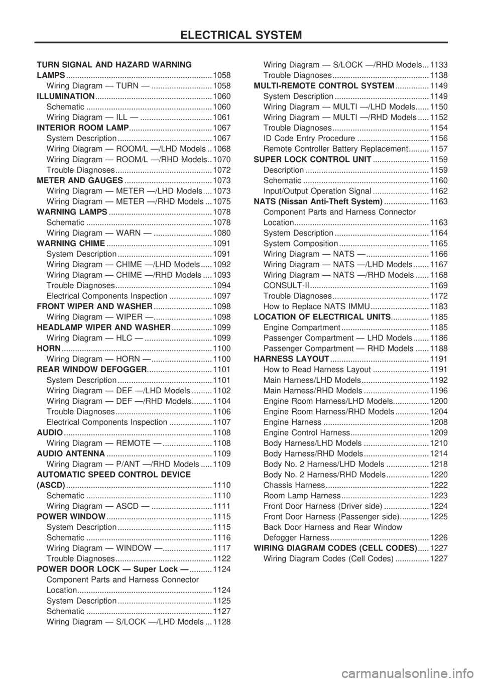
TURN SIGNAL AND HAZARD WARNING
LAMPS................................................................. 1058
Wiring Diagram Ð TURN Ð ........................... 1058
ILLUMINATION .................................................... 1060
Schematic ........................................................ 1060
Wiring Diagram Ð ILL Ð ................................ 1061
INTERIOR ROOM LAMP ..................................... 1067
System Description .......................................... 1067
Wiring Diagram Ð ROOM/L Ð/LHD Models .. 1068
Wiring Diagram Ð ROOM/L Ð/RHD Models.. 1070
Trouble Diagnoses ........................................... 1072
METER AND GAUGES ....................................... 1073
Wiring Diagram Ð METER Ð/LHD Models .... 1073
Wiring Diagram Ð METER Ð/RHD Models ... 1075
WARNING LAMPS .............................................. 1078
Schematic ........................................................ 1078
Wiring Diagram Ð WARN Ð .......................... 1080
WARNING CHIME ............................................... 1091
System Description .......................................... 1091
Wiring Diagram Ð CHIME Ð/LHD Models ..... 1092
Wiring Diagram Ð CHIME Ð/RHD Models .... 1093
Trouble Diagnoses ........................................... 1094
Electrical Components Inspection ................... 1097
FRONT WIPER AND WASHER .......................... 1098
Wiring Diagram Ð WIPER Ð.......................... 1098
HEADLAMP WIPER AND WASHER .................. 1099
Wiring Diagram Ð HLC Ð .............................. 1099
HORN ................................................................... 1100
Wiring Diagram Ð HORN Ð ........................... 1100
REAR WINDOW DEFOGGER ............................. 1101
System Description .......................................... 1101
Wiring Diagram Ð DEF Ð/LHD Models ......... 1102
Wiring Diagram Ð DEF Ð/RHD Models......... 1104
Trouble Diagnoses ........................................... 1106
Electrical Components Inspection ................... 1107
AUDIO .................................................................. 1108
Wiring Diagram Ð REMOTE Ð ...................... 1108
AUDIO ANTENNA ............................................... 1109
Wiring Diagram Ð P/ANT Ð/RHD Models ..... 1109
AUTOMATIC SPEED CONTROL DEVICE
(ASCD) ................................................................. 1110
Schematic ........................................................ 1110
Wiring Diagram Ð ASCD Ð ........................... 1111
POWER WINDOW ............................................... 1115
System Description .......................................... 1115
Schematic ........................................................ 1116
Wiring Diagram Ð WINDOW Ð...................... 1117
Trouble Diagnoses ........................................... 1122
POWER DOOR LOCK Ð Super Lock Ð .......... 1124
Component Parts and Harness Connector
Location............................................................ 1124
System Description .......................................... 1125
Schematic ........................................................ 1127
Wiring Diagram Ð S/LOCK Ð/LHD Models ... 1128 Wiring Diagram Ð S/LOCK Ð/RHD Models... 1133
Trouble Diagnoses ........................................... 1138
MULTI-REMOTE CONTROL SYSTEM ............... 1149
System Description .......................................... 1149
Wiring Diagram Ð MULTI Ð/LHD Models...... 1150
Wiring Diagram Ð MULTI Ð/RHD Models ..... 1152
Trouble Diagnoses ........................................... 1154
ID Code Entry Procedure ................................ 1156
Remote Controller Battery Replacement ......... 1157
SUPER LOCK CONTROL UNIT ......................... 1159
Description ....................................................... 1159
Schematic ........................................................ 1160
Input/Output Operation Signal ......................... 1162
NATS (Nissan Anti-Theft System) .................... 1163
Component Parts and Harness Connector
Location............................................................ 1163
System Description .......................................... 1164
System Composition ........................................ 1165
Wiring Diagram Ð NATS Ð ............................ 1166
Wiring Diagram Ð NATS Ð/LHD Models ....... 1167
Wiring Diagram Ð NATS Ð/RHD Models ...... 1168
CONSULT-II ..................................................... 1169
Trouble Diagnoses ........................................... 1172
How to Replace NATS IMMU .......................... 1183
LOCATION OF ELECTRICAL UNITS ................. 1185
Engine Compartment ....................................... 1185
Passenger Compartment Ð LHD Models ....... 1186
Passenger Compartment Ð RHD Models ...... 1188
HARNESS LAYOUT ............................................ 1191
How to Read Harness Layout ......................... 1191
Main Harness/LHD Models .............................. 1192
Main Harness/RHD Models ............................. 1196
Engine Room Harness/LHD Models................ 1200
Engine Room Harness/RHD Models ............... 1204
Engine Harness ............................................... 1208
Engine Control Harness................................... 1209
Body Harness/LHD Models ............................. 1210
Body Harness/RHD Models ............................. 1214
Body No. 2 Harness/LHD Models ................... 1218
Body No. 2 Harness/RHD Models ................... 1220
Chassis Harness .............................................. 1222
Room Lamp Harness ....................................... 1223
Front Door Harness (Driver side) .................... 1224
Front Door Harness (Passenger side)............. 1225
Back Door Harness and Rear Window
Defogger Harness ............................................ 1226
WIRING DIAGRAM CODES (CELL CODES) ..... 1227
Wiring Diagram Codes (Cell Codes) ............... 1227
ELECTRICAL SYSTEM
Page 577 of 1033
![NISSAN PATROL 2000 Electronic Repair Manual System Description
POWER SUPPLY AND GROUND
Power is supplied at all times:
+through 10A fuse [No.
20, located in the fuse block (J/B)]
+to front and rear interior room lamp terminal
V1
+through 7.5A f NISSAN PATROL 2000 Electronic Repair Manual System Description
POWER SUPPLY AND GROUND
Power is supplied at all times:
+through 10A fuse [No.
20, located in the fuse block (J/B)]
+to front and rear interior room lamp terminal
V1
+through 7.5A f](/img/5/57367/w960_57367-576.png)
System Description
POWER SUPPLY AND GROUND
Power is supplied at all times:
+through 10A fuse [No.
20, located in the fuse block (J/B)]
+to front and rear interior room lamp terminal
V1
+through 7.5A fuse [No.24, located in the fuse block (J/B)]
+to key switch terminal
V2and
+to super lock control unit terminal
V1.
When the key is removed from ignition key cylinder, power is interrupted:
+through key switch terminal
V1
+to super lock control unit terminalV18.
With the ignition key switch in the ON or START position, power is supplied:
+through 10A fuse [No.
25, located in the fuse block (J/B)]
+to super lock control unit terminal
V17.
Ground is supplied:
+to super lock control unit terminal
V16
+through body grounds terminalsM30andM19(LHD models) orM98(RHD models).
When the front driver side door is opened, ground is supplied:
+through body grounds
B23andM19(LHD models) orM98(RHD models).
+to front door switch (driver side) terminal
V3
+from front door switch (driver side) terminalV1
+to super lock control unit terminalV30.
When any other door is opened, ground is supplied to super lock control unit terminal
V31in the same man-
ner as the driver door switch.
When the front driver side door is unlocked, the super lock control unit receives a ground signal:
+through body grounds terminals
M30andM19(LHD models) orM98(RHD models).
+to front door lock actuator (driver side) (door unlock sensor) terminal
V5
+from front door lock actuator (driver side) (door unlock sensor) terminalV2
+to super lock control unit terminalV28.
When a signal, or combination of signals is received by the super lock control unit, ground is supplied:
+through super lock control unit terminal
V26
+to front interior room lamp terminalV2.
With power and ground supplied, the front interior room lamp illuminates.
INTERIOR ROOM LAMP TIMER OPERATION
When front interior room lamp switch is in the ªDOORº position, the super lock control unit keeps the front
interior room lamp illuminated for about 30 seconds when:
+unlock signal is supplied from driver's door unlock sensor while all doors are closed and key is out of
ignition key cylinder
+key is removed from ignition key cylinder while all doors are closed
+driver's door is opened and then closed while key is out of the ignition key cylinder. (However, if the
driver's door is closed with the key inserted in the ignition key cylinder after the driver's door is opened
with the key removed, the timer is operated.)
The timer is canceled when:
+driver's door is locked or
+ignition switch is turned ON.
ON-OFF CONTROL
When the driver side door, front passenger door, rear LH or RH door, back door LH or RH is opened, the
interior room lamp turns on while the interior room lamp switch is in the ªDOORº position.
INTERIOR ROOM LAMP
EL-1067
Page 582 of 1033
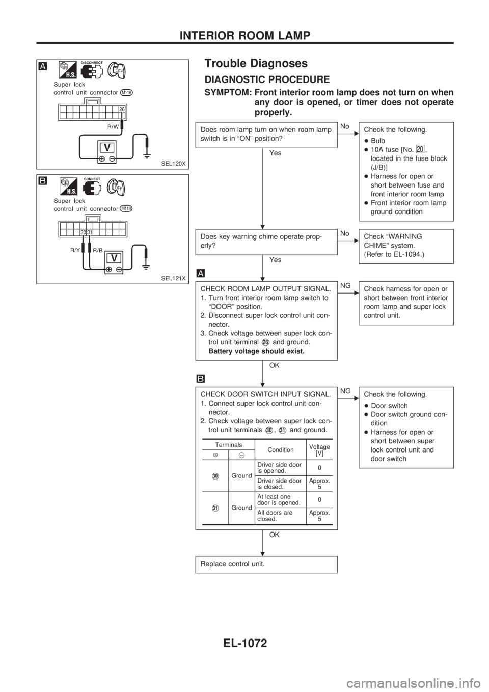
Trouble Diagnoses
DIAGNOSTIC PROCEDURE
SYMPTOM: Front interior room lamp does not turn on when
any door is opened, or timer does not operate
properly.
Does room lamp turn on when room lamp
switch is in ªONº position?
Yes
cNo
Check the following.
+Bulb
+10A fuse [No.
20,
located in the fuse block
(J/B)]
+Harness for open or
short between fuse and
front interior room lamp
+Front interior room lamp
ground condition
Does key warning chime operate prop-
erly?
Yes
cNo
Check ªWARNING
CHIMEº system.
(Refer to EL-1094.)
CHECK ROOM LAMP OUTPUT SIGNAL.
1. Turn front interior room lamp switch to
ªDOORº position.
2. Disconnect super lock control unit con-
nector.
3. Check voltage between super lock con-
trol unit terminal
V26and ground.
Battery voltage should exist.
OK
cNG
Check harness for open or
short between front interior
room lamp and super lock
control unit.
CHECK DOOR SWITCH INPUT SIGNAL.
1. Connect super lock control unit con-
nector.
2. Check voltage between super lock con-
trol unit terminals
V30,V31and ground.
OK
cNG
Check the following.
+Door switch
+Door switch ground con-
dition
+Harness for open or
short between super
lock control unit and
door switch
Replace control unit.
Terminals
ConditionVoltage
[V]
Å@
V30GroundDriver side door
is opened.0
Driver side door
is closed.Approx.
5
V31GroundAt least one
door is opened.0
All doors are
closed.Approx.
5
SEL120X
SEL121X
.
.
.
.
INTERIOR ROOM LAMP
EL-1072
Page 601 of 1033
System Description
The warning chime is combined with the super lock control unit.
Both the ignition key and light warning chime will not sound, when ignition switch in the ON or START posi-
tion (when power supply exists at super lock control unit terminal
V17).
IGNITION KEY WARNING CHIME
With the key in the ignition key cylinder, the ignition switch in the OFF or ACC position, and the driver's door
open and locked, the warning chime will sound. Power is supplied
+from key switch terminal
V1
+to super lock control unit terminalV18.
Ground is supplied
+through driver front door switch terminal
V1
+to super lock control unit terminalV30, and
+through front door lock actuator assembly (driver side) (unlock sensor) terminal
V2
+to super lock control unit terminalV28.
LIGHT WARNING CHIME
With ignition switch in the OFF or ACC position, driver's door open, and lighting switch in 1ST or 2ND
position, warning chime will sound. Power is supplied
+from combination switch terminal
V12
+to super lock control unit terminalV19.
Ground is supplied
+through driver front door switch terminal
V1
+to super lock control unit terminalV30.
WARNING CHIME
EL-1091
Page 604 of 1033
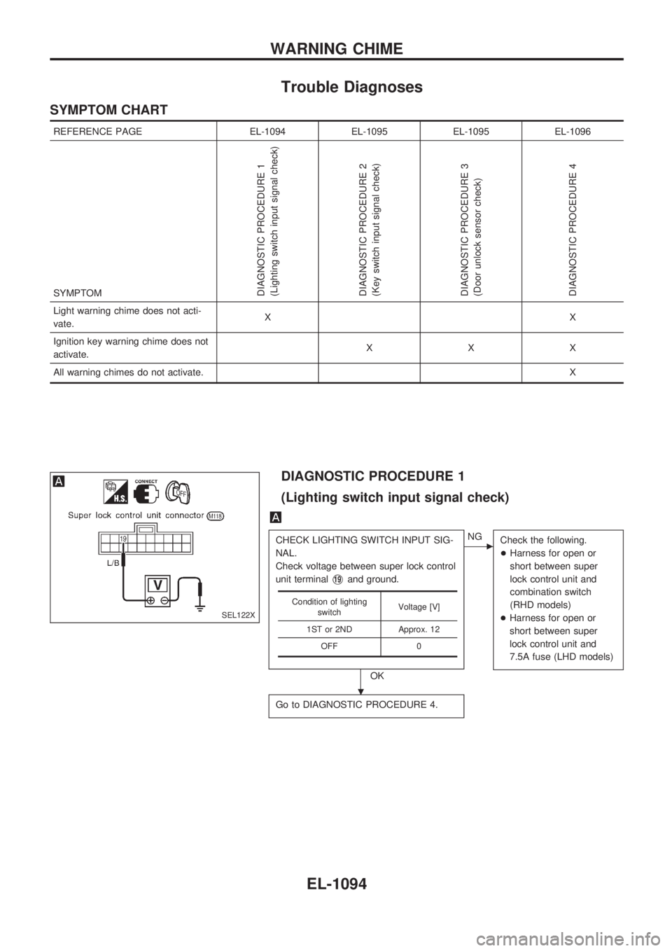
Trouble Diagnoses
SYMPTOM CHART
REFERENCE PAGE EL-1094 EL-1095 EL-1095 EL-1096
SYMPTOM
DIAGNOSTIC PROCEDURE 1
(Lighting switch input signal check)
DIAGNOSTIC PROCEDURE 2
(Key switch input signal check)
DIAGNOSTIC PROCEDURE 3
(Door unlock sensor check)
DIAGNOSTIC PROCEDURE 4
Light warning chime does not acti-
vate.XX
Ignition key warning chime does not
activate.XXX
All warning chimes do not activate.X
DIAGNOSTIC PROCEDURE 1
(Lighting switch input signal check)
CHECK LIGHTING SWITCH INPUT SIG-
NAL.
Check voltage between super lock control
unit terminal
V19and ground.
OK
cNG
Check the following.
+Harness for open or
short between super
lock control unit and
combination switch
(RHD models)
+Harness for open or
short between super
lock control unit and
7.5A fuse (LHD models)
Go to DIAGNOSTIC PROCEDURE 4.
Condition of lighting
switchVoltage [V]
1ST or 2ND Approx. 12
OFF 0
SEL122X
.
WARNING CHIME
EL-1094
Page 605 of 1033
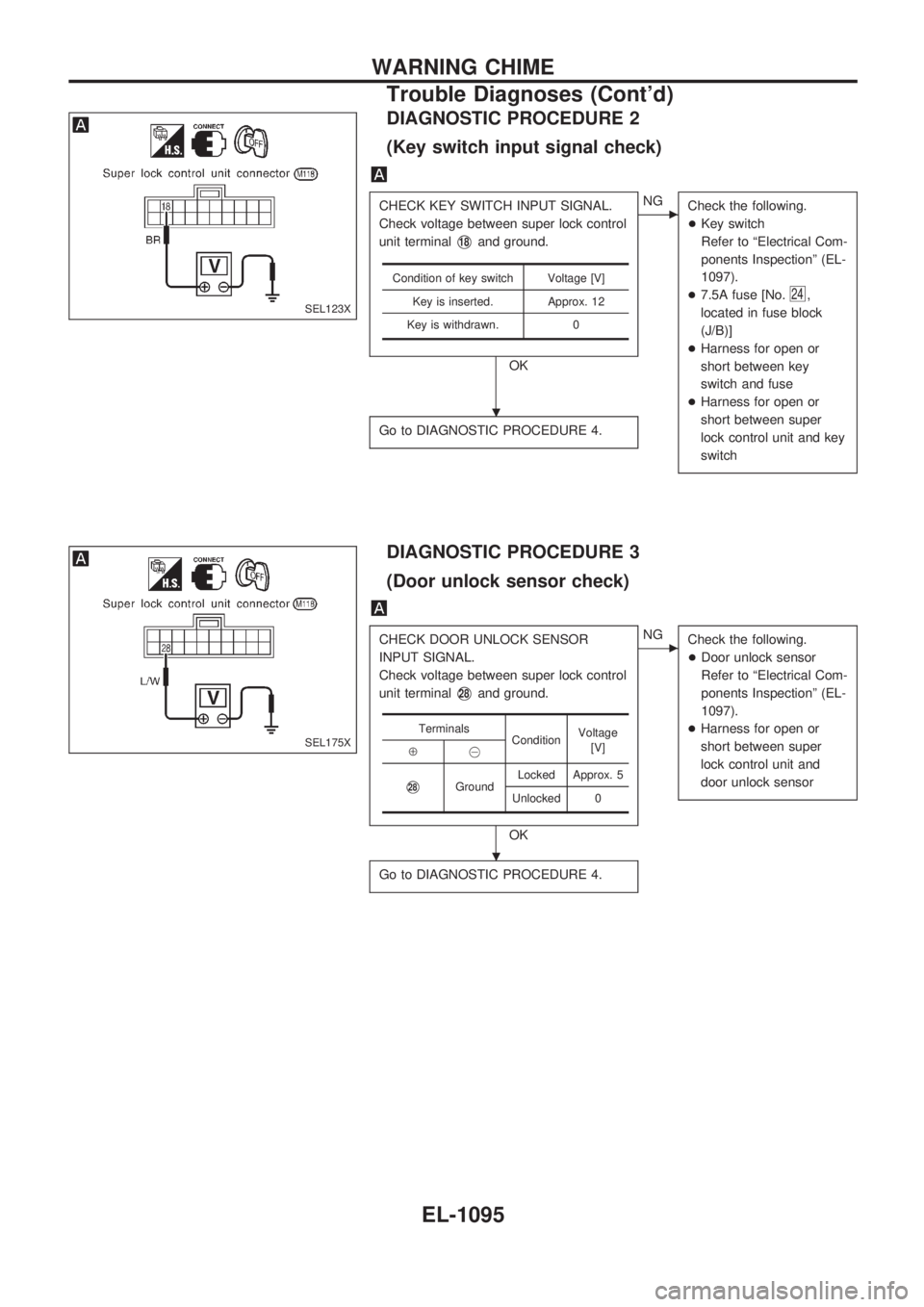
DIAGNOSTIC PROCEDURE 2
(Key switch input signal check)
CHECK KEY SWITCH INPUT SIGNAL.
Check voltage between super lock control
unit terminal
V18and ground.
OK
cNG
Check the following.
+Key switch
Refer to ªElectrical Com-
ponents Inspectionº (EL-
1097).
+7.5A fuse [No.
24,
located in fuse block
(J/B)]
+Harness for open or
short between key
switch and fuse
+Harness for open or
short between super
lock control unit and key
switch
Go to DIAGNOSTIC PROCEDURE 4.
Condition of key switch Voltage [V]
Key is inserted. Approx. 12
Key is withdrawn. 0
DIAGNOSTIC PROCEDURE 3
(Door unlock sensor check)
CHECK DOOR UNLOCK SENSOR
INPUT SIGNAL.
Check voltage between super lock control
unit terminal
V28and ground.
OK
cNG
Check the following.
+Door unlock sensor
Refer to ªElectrical Com-
ponents Inspectionº (EL-
1097).
+Harness for open or
short between super
lock control unit and
door unlock sensor
Go to DIAGNOSTIC PROCEDURE 4.
Terminals
ConditionVoltage
[V]
Å@
V28GroundLocked Approx. 5
Unlocked 0
SEL123X
SEL175X
.
.
WARNING CHIME
Trouble Diagnoses (Cont'd)
EL-1095
Page 606 of 1033
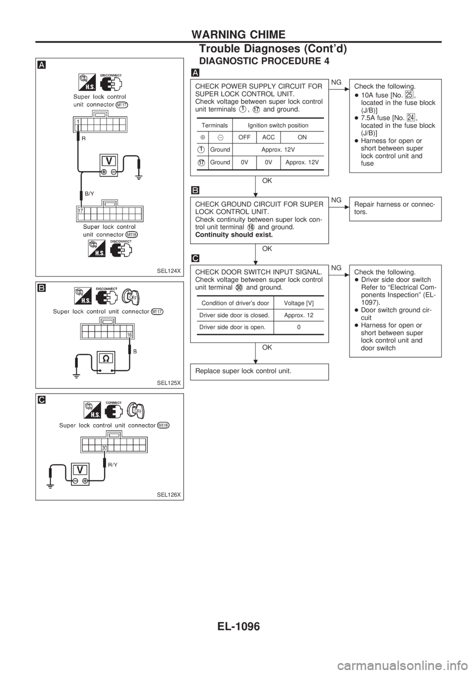
DIAGNOSTIC PROCEDURE 4
CHECK POWER SUPPLY CIRCUIT FOR
SUPER LOCK CONTROL UNIT.
Check voltage between super lock control
unit terminals
V1,V17and ground.
OK
cNG
Check the following.
+10A fuse [No.
25,
located in the fuse block
(J/B)]
+7.5A fuse [No.
24,
located in the fuse block
(J/B)]
+Harness for open or
short between super
lock control unit and
fuse
CHECK GROUND CIRCUIT FOR SUPER
LOCK CONTROL UNIT.
Check continuity between super lock con-
trol unit terminal
V16and ground.
Continuity should exist.
OK
cNG
Repair harness or connec-
tors.
CHECK DOOR SWITCH INPUT SIGNAL.
Check voltage between super lock control
unit terminal
V30and ground.
OK
cNG
Check the following.
+Driver side door switch
Refer to ªElectrical Com-
ponents Inspectionº (EL-
1097).
+Door switch ground cir-
cuit
+Harness for open or
short between super
lock control unit and
door switch
Replace super lock control unit.
Terminals Ignition switch position
Å@OFF ACC ON
V1Ground Approx. 12V
V17Ground 0V 0V Approx. 12V
Condition of driver's door Voltage [V]
Driver side door is closed. Approx. 12
Driver side door is open. 0
SEL124X
SEL125X
SEL126X
.
.
.
WARNING CHIME
Trouble Diagnoses (Cont'd)
EL-1096
Page 607 of 1033
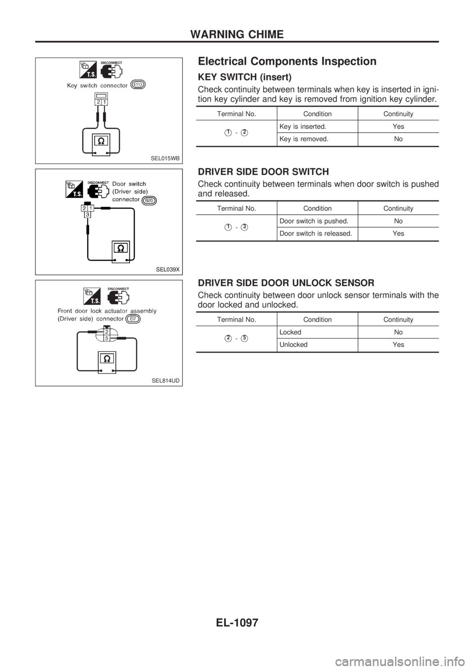
Electrical Components Inspection
KEY SWITCH (insert)
Check continuity between terminals when key is inserted in igni-
tion key cylinder and key is removed from ignition key cylinder.
Terminal No. Condition Continuity
V1-V2Key is inserted. Yes
Key is removed. No
DRIVER SIDE DOOR SWITCH
Check continuity between terminals when door switch is pushed
and released.
Terminal No. Condition Continuity
V1-V3Door switch is pushed. No
Door switch is released. Yes
DRIVER SIDE DOOR UNLOCK SENSOR
Check continuity between door unlock sensor terminals with the
door locked and unlocked.
Terminal No. Condition Continuity
V2-V5Locked No
Unlocked Yes
SEL015WB
SEL039X
SEL814UD
WARNING CHIME
EL-1097
Page 611 of 1033
System Description
The rear window defogger system is controlled by the super lock control unit. The rear window defogger
operates only for approximately 15 minutes.
Power is supplied at all times
+to rear window defogger relay terminal
V3
+through 15A fuse (No.43, located in the fuse and fusible link box),
+to rear window defogger relay terminal
V6
+through 20A fuse (No.44, located in the fuse and fusible link box) and
+to super lock control unit terminal
V1
+through 7.5A fuse [No.24, located in the fuse block (J/B)].
With the ignition switch in the ON or START position, power is supplied
+to the rear window defogger relay terminal
V1
+through 7.5A fuse [No.8, located in the fuse block (J/B)] and
+to super lock control unit terminal
V17
+through 10A fuse [No.25, located in the fuse block (J/B)].
Ground is supplied to terminal
V2of the rear window defogger switch through body grounds.
When the rear window defogger switch is turned ON, ground is supplied
+through terminal
V1of the rear window defogger switch
+to super lock control unit terminal
V35.
Terminal
V27of the super lock control unit then supplies ground to the rear window defogger relay terminal
V2.
With power and ground supplied, the rear window defogger relay is energized.
Power is supplied
+through terminals
V5andV7of the rear window defogger relay
+to the rear window defogger and door mirror defogger (with door mirror defogger).
The rear window defogger has an independent ground.
With power and ground supplied, the rear window defogger filaments heat and defog the rear window.
When the system is activated, the rear window defogger indicator illuminates in the rear window defogger
switch.
Power is supplied
+to terminal
V3of the rear window defogger switch
+from terminal
V5of the rear window defogger relay.
Terminal
V4of the rear window defogger switch is grounded through body grounds.
REAR WINDOW DEFOGGER
EL-1101
Page 625 of 1033
System Description
OUTLINE
Power window system consists of
+CPU (combined with power window main switch)
+four power window regulators
When ignition switch is in the ªONº position, power window can be operated depending on power window
sub/main switch condition.
OPERATIVE CONDITION
+Power windows can be raised or lowered with each sub-switch or the power window main switch located
on the driver's door trim when ignition switch is in the ªONº position and power window lock switch on the
driver's door trim is unlocked.
+When power window lock switch is locked, no windows can be raised or lowered except for driver's side
window.
+When ignition switch is in the ªONº position, to fully open/close the driver's side window, press down/
pull up completely on the automatic switch (main switch) and release it; it needs not be held. The win-
dow will automatically open/close all the way. To stop the window, pull up/press down then release the
switch.
+After turning ignition switch to OFF, the driver's side window can be raised or lowered for 15 minutes.
The timer control for supplying power after turning ignition switch to OFF will be canceled when the driv-
er's side door is open and then closed.
INTERRUPTION DETECTION FUNCTION
CPU (combined with power window main switch) monitors the power window regulator motor operation and
the power window position (full closed or other) for driver's power window by the signals from encoder and
limit switch in front power window regulator (driver's side).
When CPU (combined with power window main switch) detects interruption during the following close
operation in the driver's side door,
+automatic close operation when ignition switch is in the ªONº position
+automatic close operation during power window timer operation
+manual close operation during power window timer operation
CPU (combined with power window main switch) controls driver's power window regulator motor for open
and the power window will be lowered about 150 mm (5.91 in).
POWER WINDOW
EL-1115