fuel pressure NISSAN PATROL 2000 Electronic Repair Manual
[x] Cancel search | Manufacturer: NISSAN, Model Year: 2000, Model line: PATROL, Model: NISSAN PATROL 2000Pages: 1033, PDF Size: 30.71 MB
Page 236 of 1033
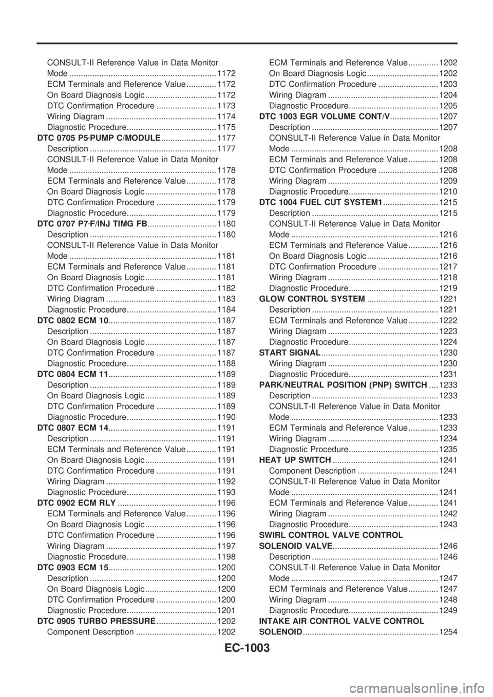
CONSULT-II Reference Value in Data Monitor
Mode ................................................................ 1172
ECM Terminals and Reference Value ............. 1172
On Board Diagnosis Logic ............................... 1172
DTC Confirmation Procedure .......................... 1173
Wiring Diagram ................................................ 1174
Diagnostic Procedure....................................... 1175
DTC 0705 P5zPUMP C/MODULE........................ 1177
Description ....................................................... 1177
CONSULT-II Reference Value in Data Monitor
Mode ................................................................ 1178
ECM Terminals and Reference Value ............. 1178
On Board Diagnosis Logic ............................... 1178
DTC Confirmation Procedure .......................... 1179
Diagnostic Procedure....................................... 1179
DTC 0707 P7zF/INJ TIMG FB.............................. 1180
Description ....................................................... 1180
CONSULT-II Reference Value in Data Monitor
Mode ................................................................ 1181
ECM Terminals and Reference Value ............. 1181
On Board Diagnosis Logic ............................... 1181
DTC Confirmation Procedure .......................... 1182
Wiring Diagram ................................................ 1183
Diagnostic Procedure....................................... 1184
DTC 0802 ECM 10............................................... 1187
Description ....................................................... 1187
On Board Diagnosis Logic ............................... 1187
DTC Confirmation Procedure .......................... 1187
Diagnostic Procedure....................................... 1188
DTC 0804 ECM 11............................................... 1189
Description ....................................................... 1189
On Board Diagnosis Logic ............................... 1189
DTC Confirmation Procedure .......................... 1189
Diagnostic Procedure....................................... 1190
DTC 0807 ECM 14............................................... 1191
Description ....................................................... 1191
ECM Terminals and Reference Value ............. 1191
On Board Diagnosis Logic ............................... 1191
DTC Confirmation Procedure .......................... 1191
Wiring Diagram ................................................ 1192
Diagnostic Procedure....................................... 1193
DTC 0902 ECM RLY........................................... 1196
ECM Terminals and Reference Value ............. 1196
On Board Diagnosis Logic ............................... 1196
DTC Confirmation Procedure .......................... 1196
Wiring Diagram ................................................ 1197
Diagnostic Procedure....................................... 1198
DTC 0903 ECM 15............................................... 1200
Description ....................................................... 1200
On Board Diagnosis Logic ............................... 1200
DTC Confirmation Procedure .......................... 1200
Diagnostic Procedure....................................... 1201
DTC 0905 TURBO PRESSURE.......................... 1202
Component Description ................................... 1202ECM Terminals and Reference Value ............. 1202
On Board Diagnosis Logic ............................... 1202
DTC Confirmation Procedure .......................... 1203
Wiring Diagram ................................................ 1204
Diagnostic Procedure....................................... 1205
DTC 1003 EGR VOLUME CONT/V..................... 1207
Description ....................................................... 1207
CONSULT-II Reference Value in Data Monitor
Mode ................................................................ 1208
ECM Terminals and Reference Value ............. 1208
DTC Confirmation Procedure .......................... 1208
Wiring Diagram ................................................ 1209
Diagnostic Procedure....................................... 1210
DTC 1004 FUEL CUT SYSTEM1........................ 1215
Description ....................................................... 1215
CONSULT-II Reference Value in Data Monitor
Mode ................................................................ 1216
ECM Terminals and Reference Value ............. 1216
On Board Diagnosis Logic ............................... 1216
DTC Confirmation Procedure .......................... 1217
Wiring Diagram ................................................ 1218
Diagnostic Procedure....................................... 1219
GLOW CONTROL SYSTEM............................... 1221
Description ....................................................... 1221
ECM Terminals and Reference Value ............. 1222
Wiring Diagram ................................................ 1223
Diagnostic Procedure....................................... 1224
START SIGNAL................................................... 1230
Wiring Diagram ................................................ 1230
Diagnostic Procedure....................................... 1231
PARK/NEUTRAL POSITION (PNP) SWITCH.... 1233
Description ....................................................... 1233
CONSULT-II Reference Value in Data Monitor
Mode ................................................................ 1233
ECM Terminals and Reference Value ............. 1233
Wiring Diagram ................................................ 1234
Diagnostic Procedure....................................... 1235
HEAT UP SWITCH.............................................. 1241
Component Description ................................... 1241
CONSULT-II Reference Value in Data Monitor
Mode ................................................................ 1241
ECM Terminals and Reference Value ............. 1241
Wiring Diagram ................................................ 1242
Diagnostic Procedure....................................... 1243
SWIRL CONTROL VALVE CONTROL
SOLENOID VALVE.............................................. 1246
Description ....................................................... 1246
CONSULT-II Reference Value in Data Monitor
Mode ................................................................ 1247
ECM Terminals and Reference Value ............. 1247
Wiring Diagram ................................................ 1248
Diagnostic Procedure....................................... 1249
INTAKE AIR CONTROL VALVE CONTROL
SOLENOID........................................................... 1254
EC-1003
Page 239 of 1033
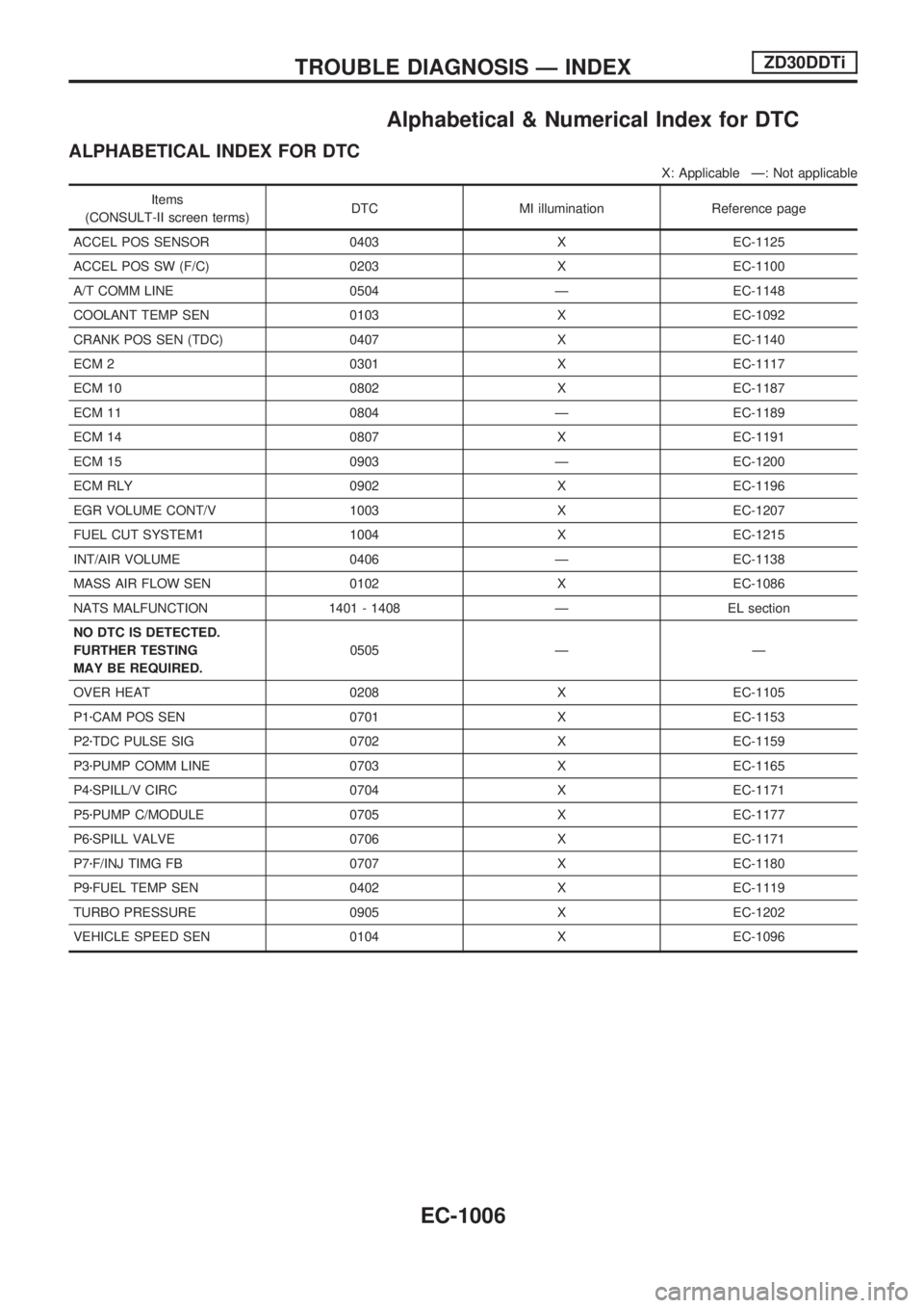
Alphabetical & Numerical Index for DTC
ALPHABETICAL INDEX FOR DTC
X: Applicable Ð: Not applicable
Items
(CONSULT-II screen terms)DTC MI illumination Reference page
ACCEL POS SENSOR 0403 X EC-1125
ACCEL POS SW (F/C) 0203 X EC-1100
A/T COMM LINE 0504 Ð EC-1148
COOLANT TEMP SEN 0103 X EC-1092
CRANK POS SEN (TDC) 0407 X EC-1140
ECM 2 0301 X EC-1117
ECM 10 0802 X EC-1187
ECM 11 0804 Ð EC-1189
ECM 14 0807 X EC-1191
ECM 15 0903 Ð EC-1200
ECM RLY 0902 X EC-1196
EGR VOLUME CONT/V 1003 X EC-1207
FUEL CUT SYSTEM1 1004 X EC-1215
INT/AIR VOLUME 0406 Ð EC-1138
MASS AIR FLOW SEN 0102 X EC-1086
NATS MALFUNCTION 1401 - 1408 Ð EL section
NO DTC IS DETECTED.
FURTHER TESTING
MAY BE REQUIRED.0505 Ð Ð
OVER HEAT 0208 X EC-1105
P1zCAM POS SEN 0701 X EC-1153
P2zTDC PULSE SIG 0702 X EC-1159
P3zPUMP COMM LINE 0703 X EC-1165
P4zSPILL/V CIRC 0704 X EC-1171
P5zPUMP C/MODULE 0705 X EC-1177
P6zSPILL VALVE 0706 X EC-1171
P7zF/INJ TIMG FB 0707 X EC-1180
P9zFUEL TEMP SEN 0402 X EC-1119
TURBO PRESSURE 0905 X EC-1202
VEHICLE SPEED SEN 0104 X EC-1096
TROUBLE DIAGNOSIS Ð INDEXZD30DDTi
EC-1006
Page 240 of 1033
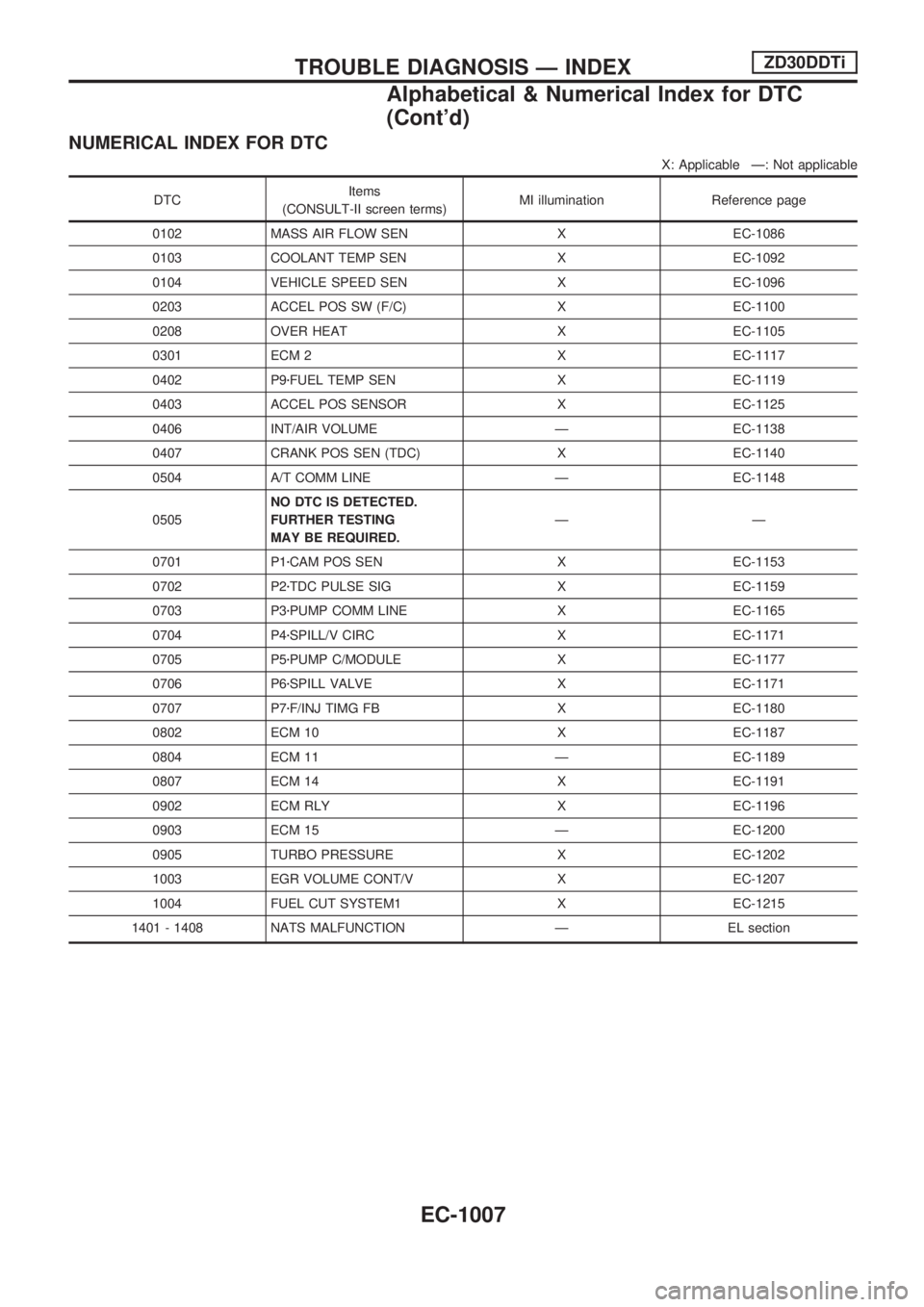
NUMERICAL INDEX FOR DTC
X: Applicable Ð: Not applicable
DTCItems
(CONSULT-II screen terms)MI illumination Reference page
0102 MASS AIR FLOW SEN X EC-1086
0103 COOLANT TEMP SEN X EC-1092
0104 VEHICLE SPEED SEN X EC-1096
0203 ACCEL POS SW (F/C) X EC-1100
0208 OVER HEAT X EC-1105
0301 ECM 2 X EC-1117
0402 P9zFUEL TEMP SEN X EC-1119
0403 ACCEL POS SENSOR X EC-1125
0406 INT/AIR VOLUME Ð EC-1138
0407 CRANK POS SEN (TDC) X EC-1140
0504 A/T COMM LINE Ð EC-1148
0505NO DTC IS DETECTED.
FURTHER TESTING
MAY BE REQUIRED.ÐÐ
0701 P1zCAM POS SEN X EC-1153
0702 P2zTDC PULSE SIG X EC-1159
0703 P3zPUMP COMM LINE X EC-1165
0704 P4zSPILL/V CIRC X EC-1171
0705 P5zPUMP C/MODULE X EC-1177
0706 P6zSPILL VALVE X EC-1171
0707 P7zF/INJ TIMG FB X EC-1180
0802 ECM 10 X EC-1187
0804 ECM 11 Ð EC-1189
0807 ECM 14 X EC-1191
0902 ECM RLY X EC-1196
0903 ECM 15 Ð EC-1200
0905 TURBO PRESSURE X EC-1202
1003 EGR VOLUME CONT/V X EC-1207
1004 FUEL CUT SYSTEM1 X EC-1215
1401 - 1408 NATS MALFUNCTION Ð EL section
TROUBLE DIAGNOSIS Ð INDEXZD30DDTi
Alphabetical & Numerical Index for DTC
(Cont'd)
EC-1007
Page 251 of 1033
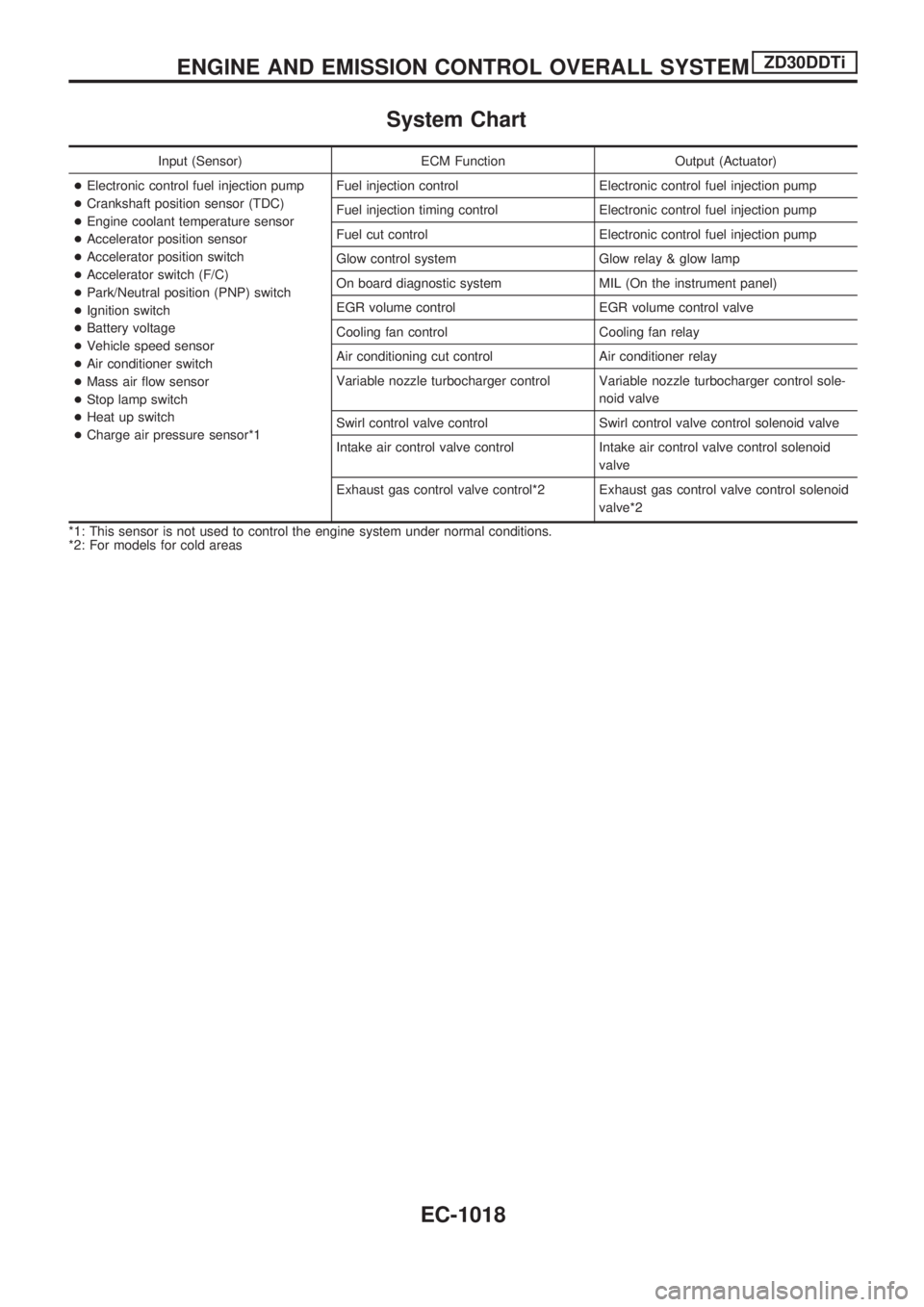
System Chart
Input (Sensor) ECM Function Output (Actuator)
+Electronic control fuel injection pump
+Crankshaft position sensor (TDC)
+Engine coolant temperature sensor
+Accelerator position sensor
+Accelerator position switch
+Accelerator switch (F/C)
+Park/Neutral position (PNP) switch
+Ignition switch
+Battery voltage
+Vehicle speed sensor
+Air conditioner switch
+Mass air flow sensor
+Stop lamp switch
+Heat up switch
+Charge air pressure sensor*1Fuel injection control Electronic control fuel injection pump
Fuel injection timing control Electronic control fuel injection pump
Fuel cut control Electronic control fuel injection pump
Glow control system Glow relay & glow lamp
On board diagnostic system MIL (On the instrument panel)
EGR volume control EGR volume control valve
Cooling fan control Cooling fan relay
Air conditioning cut control Air conditioner relay
Variable nozzle turbocharger control Variable nozzle turbocharger control sole-
noid valve
Swirl control valve control Swirl control valve control solenoid valve
Intake air control valve control Intake air control valve control solenoid
valve
Exhaust gas control valve control*2 Exhaust gas control valve control solenoid
valve*2
*1: This sensor is not used to control the engine system under normal conditions.
*2: For models for cold areas
ENGINE AND EMISSION CONTROL OVERALL SYSTEMZD30DDTi
EC-1018
Page 258 of 1033
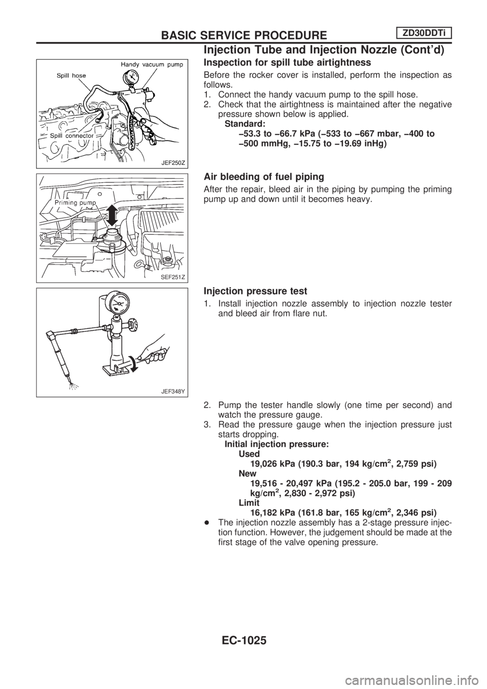
Inspection for spill tube airtightness
Before the rocker cover is installed, perform the inspection as
follows.
1. Connect the handy vacuum pump to the spill hose.
2. Check that the airtightness is maintained after the negative
pressure shown below is applied.
Standard:
þ53.3 to þ66.7 kPa (þ533 to þ667 mbar, þ400 to
þ500 mmHg, þ15.75 to þ19.69 inHg)
Air bleeding of fuel piping
After the repair, bleed air in the piping by pumping the priming
pump up and down until it becomes heavy.
Injection pressure test
1. Install injection nozzle assembly to injection nozzle tester
and bleed air from flare nut.
2. Pump the tester handle slowly (one time per second) and
watch the pressure gauge.
3. Read the pressure gauge when the injection pressure just
starts dropping.
Initial injection pressure:
Used
19,026 kPa (190.3 bar, 194 kg/cm
2, 2,759 psi)
New
19,516 - 20,497 kPa (195.2 - 205.0 bar, 199 - 209
kg/cm
2, 2,830 - 2,972 psi)
Limit
16,182 kPa (161.8 bar, 165 kg/cm
2, 2,346 psi)
+The injection nozzle assembly has a 2-stage pressure injec-
tion function. However, the judgement should be made at the
first stage of the valve opening pressure.
JEF250Z
SEF251Z
JEF348Y
BASIC SERVICE PROCEDUREZD30DDTi
Injection Tube and Injection Nozzle (Cont'd)
EC-1025
Page 272 of 1033
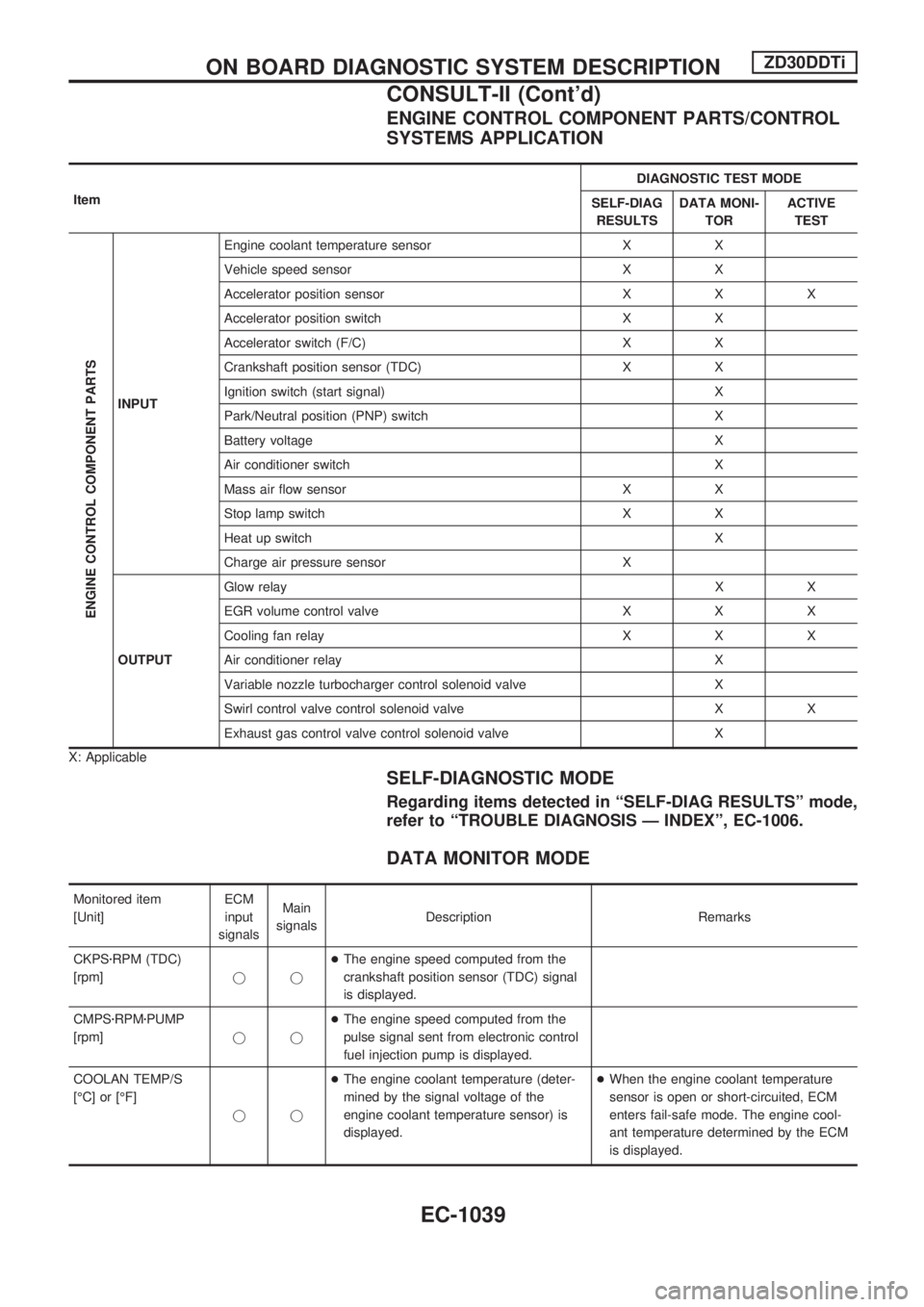
ENGINE CONTROL COMPONENT PARTS/CONTROL
SYSTEMS APPLICATION
ItemDIAGNOSTIC TEST MODE
SELF-DIAG
RESULTSDATA MONI-
TORACTIVE
TEST
ENGINE CONTROL COMPONENT PARTS
INPUTEngine coolant temperature sensor X X
Vehicle speed sensor X X
Accelerator position sensor X X X
Accelerator position switch X X
Accelerator switch (F/C) X X
Crankshaft position sensor (TDC) X X
Ignition switch (start signal) X
Park/Neutral position (PNP) switch X
Battery voltage X
Air conditioner switch X
Mass air flow sensor X X
Stop lamp switch X X
Heat up switch X
Charge air pressure sensor X
OUTPUTGlow relayXX
EGR volume control valve X X X
Cooling fan relay X X X
Air conditioner relay X
Variable nozzle turbocharger control solenoid valve X
Swirl control valve control solenoid valve X X
Exhaust gas control valve control solenoid valve X
X: Applicable
SELF-DIAGNOSTIC MODE
Regarding items detected in ªSELF-DIAG RESULTSº mode,
refer to ªTROUBLE DIAGNOSIS Ð INDEXº, EC-1006.
DATA MONITOR MODE
Monitored item
[Unit]ECM
input
signalsMain
signalsDescription Remarks
CKPSzRPM (TDC)
[rpm]jj+The engine speed computed from the
crankshaft position sensor (TDC) signal
is displayed.
CMPSzRPMzPUMP
[rpm]jj+The engine speed computed from the
pulse signal sent from electronic control
fuel injection pump is displayed.
COOLAN TEMP/S
[ÉC] or [ÉF]
jj+The engine coolant temperature (deter-
mined by the signal voltage of the
engine coolant temperature sensor) is
displayed.+When the engine coolant temperature
sensor is open or short-circuited, ECM
enters fail-safe mode. The engine cool-
ant temperature determined by the ECM
is displayed.
ON BOARD DIAGNOSTIC SYSTEM DESCRIPTIONZD30DDTi
CONSULT-II (Cont'd)
EC-1039
Page 286 of 1033
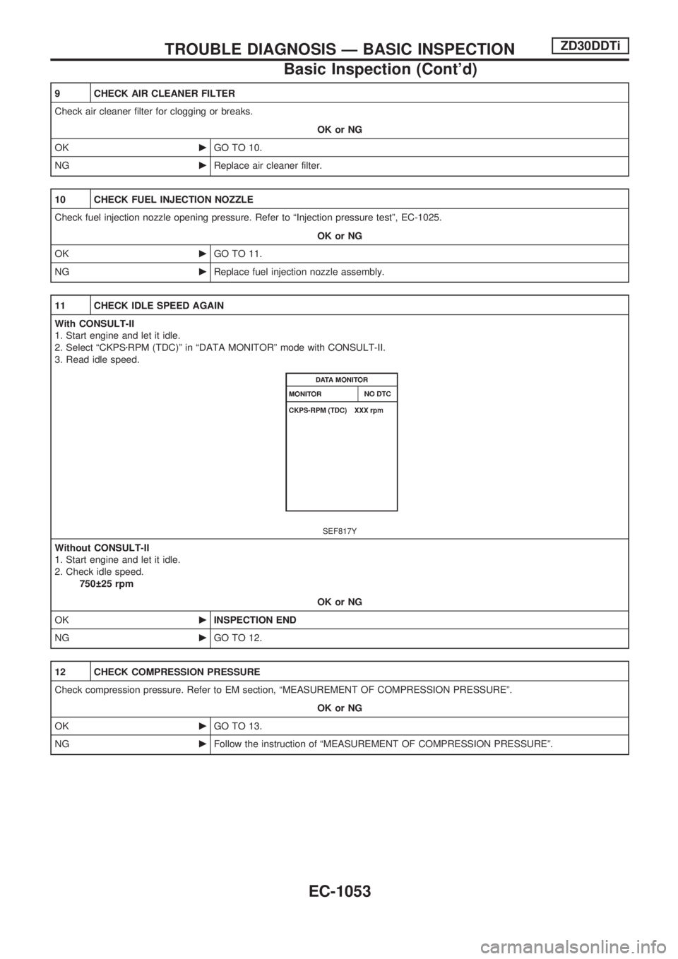
9 CHECK AIR CLEANER FILTER
Check air cleaner filter for clogging or breaks.
OK or NG
OKcGO TO 10.
NGcReplace air cleaner filter.
10 CHECK FUEL INJECTION NOZZLE
Check fuel injection nozzle opening pressure. Refer to ªInjection pressure testº, EC-1025.
OK or NG
OKcGO TO 11.
NGcReplace fuel injection nozzle assembly.
11 CHECK IDLE SPEED AGAIN
With CONSULT-II
1. Start engine and let it idle.
2. Select ªCKPSzRPM (TDC)º in ªDATA MONITORº mode with CONSULT-II.
3. Read idle speed.
SEF817Y
Without CONSULT-II
1. Start engine and let it idle.
2. Check idle speed.
750 25 rpm
OK or NG
OKcINSPECTION END
NGcGO TO 12.
12 CHECK COMPRESSION PRESSURE
Check compression pressure. Refer to EM section, ªMEASUREMENT OF COMPRESSION PRESSUREº.
OK or NG
OKcGO TO 13.
NGcFollow the instruction of ªMEASUREMENT OF COMPRESSION PRESSUREº.
TROUBLE DIAGNOSIS Ð BASIC INSPECTIONZD30DDTi
Basic Inspection (Cont'd)
EC-1053
Page 288 of 1033
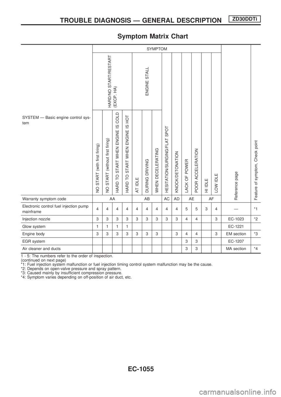
Symptom Matrix Chart
SYSTEM Ð Basic engine control sys-
temSYMPTOM
Reference page
Feature of symptom, Check pointHARD/NO START/RESTART
(EXCP. HA)
ENGINE STALL
HESITATION/SURGING/FLAT SPOT
KNOCK/DETONATION
LACK OF POWER
POOR ACCELERATION
HI IDLE
LOW IDLE NO START (with first firing)
NO START (without first firing)
HARD TO START WHEN ENGINE IS COLD
HARD TO START WHEN ENGINE IS HOT
AT IDLE
DURING DRIVING
WHEN DECELERATINGWarranty symptom code AA AB AC AD AE AF
Electronic control fuel injection pump
mainframe4444444445534 Ð *1
Injection nozzle33333333344 3EC-1023 *2
Glow system1111EC-1221
Engine body3333333 344 3 EMsection *3
EGR system3 3 EC-1207
Air cleaner and ducts 3 3 MA section *4
1 - 5: The numbers refer to the order of inspection.
(continued on next page)
*1: Fuel injection system malfunction or fuel injection timing control system malfunction may be the cause.
*2: Depends on open-valve pressure and spray pattern.
*3: Caused mainly by insufficient compression pressure.
*4: Symptom varies depending on off-position of air duct, etc.
TROUBLE DIAGNOSIS Ð GENERAL DESCRIPTIONZD30DDTi
EC-1055
Page 289 of 1033
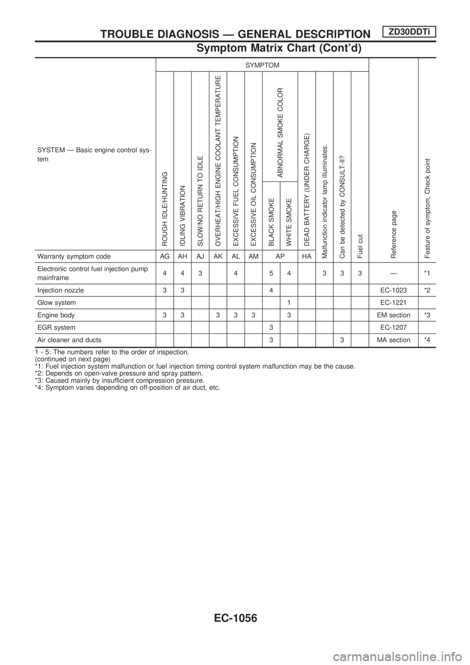
SYSTEM Ð Basic engine control sys-
temSYMPTOM
Reference page
Feature of symptom, Check pointROUGH IDLE/HUNTING
IDLING VIBRATION
SLOW/NO RETURN TO IDLE
OVERHEAT/HIGH ENGINE COOLANT TEMPERATURE
EXCESSIVE FUEL CONSUMPTION
EXCESSIVE OIL CONSUMPTION
ABNORMAL SMOKE COLOR
DEAD BATTERY (UNDER CHARGE)
Malfunction indicator lamp illuminates.
Can be detected by CONSULT-II?
Fuel cutBLACK SMOKE
WHITE SMOKEWarranty symptom code AG AH AJ AK AL AM AP HA
Electronic control fuel injection pump
mainframe443 4 54 333 Ð *1
Injection nozzle 3 3 4 EC-1023 *2
Glow system 1 EC-1221
Engine body 3 3 3 3 3 3 EM section *3
EGR system 3 EC-1207
Air cleaner and ducts 3 3 MA section *4
1 - 5: The numbers refer to the order of inspection.
(continued on next page)
*1: Fuel injection system malfunction or fuel injection timing control system malfunction may be the cause.
*2: Depends on open-valve pressure and spray pattern.
*3: Caused mainly by insufficient compression pressure.
*4: Symptom varies depending on off-position of air duct, etc.
TROUBLE DIAGNOSIS Ð GENERAL DESCRIPTIONZD30DDTi
Symptom Matrix Chart (Cont'd)
EC-1056
Page 292 of 1033
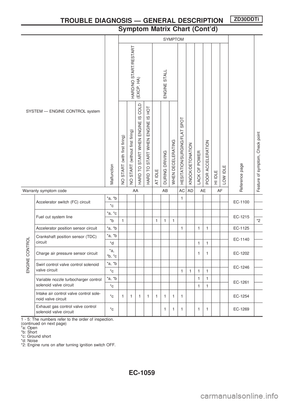
SYSTEM Ð ENGINE CONTROL system
Malfunction
SYMPTOM
Reference page
Feature of symptom, Check pointHARD/NO START/RESTART
(EXCP. HA)
ENGINE STALL
HESITATION/SURGING/FLAT SPOT
KNOCK/DETONATION
LACK OF POWER
POOR ACCELERATION
HI IDLE
LOW IDLE NO START (with first firing)
NO START (without first firing)
HARD TO START WHEN ENGINE IS COLD
HARD TO START WHEN ENGINE IS HOT
AT IDLE
DURING DRIVING
WHEN DECELERATINGWarranty symptom code AA AB AC AD AE AF
ENGINE CONTROL
Accelerator switch (FC) circuit*a, *b 1
EC-1100
*c
Fuel cut system line*a, *c
EC-1215
*b 1 1 1 1 *2
Accelerator position sensor circuit *a, *b 1 1 1 EC-1125
Crankshaft position sensor (TDC)
circuit*a, *b
EC-1140
*d 1 1
Charge air pressure sensor circuit*a,
*b, *c1 1 EC-1202
Swirl control valve control solenoid
valve circuit*a, *b
EC-1246
*c 1111
Variable nozzle turbocharger control
solenoid valve circuit*a, *b 1 1
EC-1261
*c 1 1
Intake air control valve control sole-
noid valve circuit*c 11111111EC-1254
Exhaust gas control valve control
solenoid valve circuit*c 1 1 1 1 1 EC-1269
1 - 5: The numbers refer to the order of inspection.
(continued on next page)
*a: Open
*b: Short
*c: Ground short
*d: Noise
*2: Engine runs on after turning ignition switch OFF.
TROUBLE DIAGNOSIS Ð GENERAL DESCRIPTIONZD30DDTi
Symptom Matrix Chart (Cont'd)
EC-1059