ignition NISSAN PATROL 2001 Electronic Repair Manual
[x] Cancel search | Manufacturer: NISSAN, Model Year: 2001, Model line: PATROL, Model: NISSAN PATROL 2001Pages: 273, PDF Size: 9.05 MB
Page 48 of 273
Diagnostic Procedure
1 INSPECTION START
Do you have CONSULT-II?
Yes or No
YescGO TO 2.
NocGO TO 3.
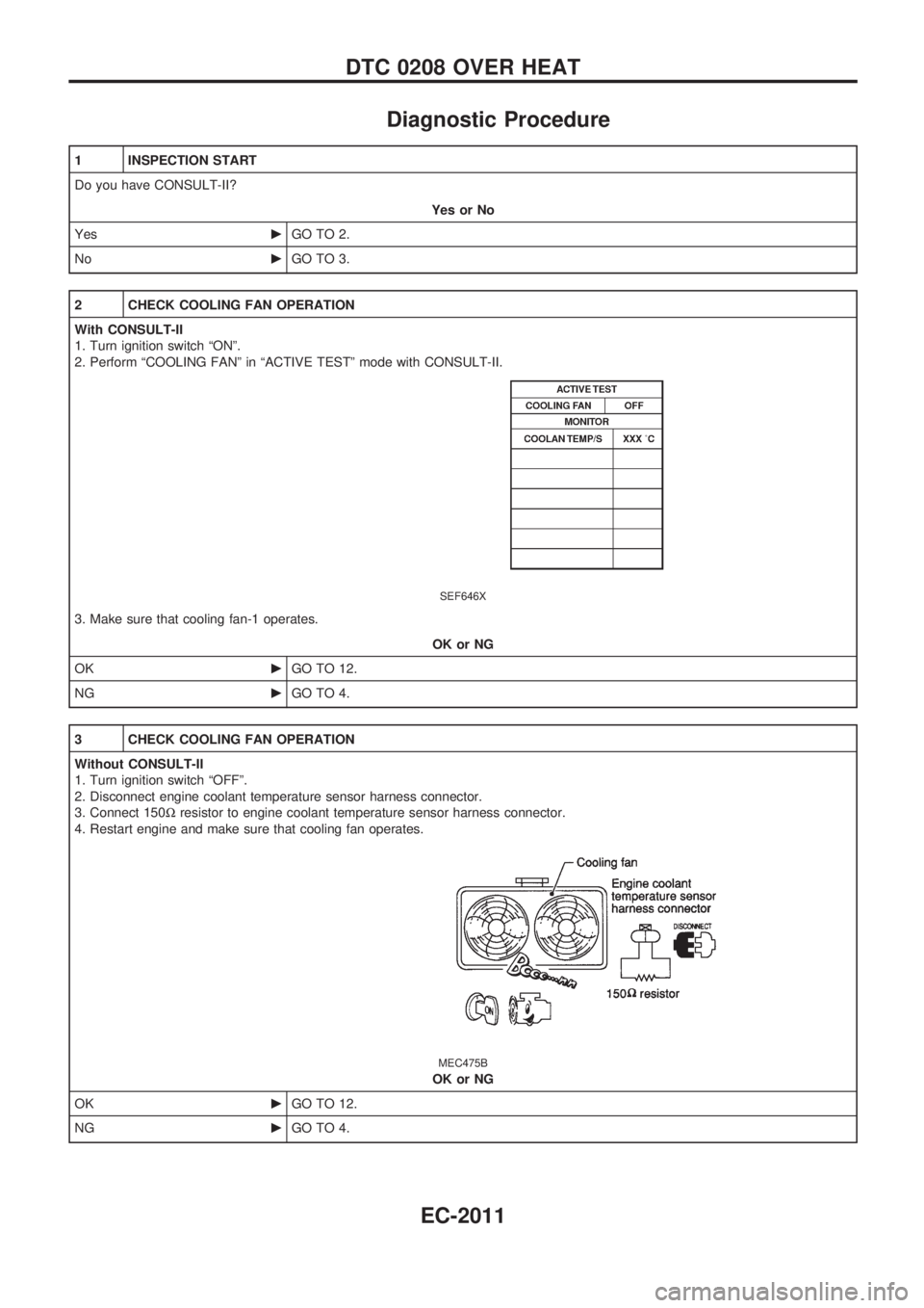
2 CHECK COOLING FAN OPERATION
With CONSULT-II
1. Turn ignition switch ªONº.
2. Perform ªCOOLING FANº in ªACTIVE TESTº mode with CONSULT-II.
SEF646X
3. Make sure that cooling fan-1 operates.
OK or NG
OKcGO TO 12.
NGcGO TO 4.
3 CHECK COOLING FAN OPERATION
Without CONSULT-II
1. Turn ignition switch ªOFFº.
2. Disconnect engine coolant temperature sensor harness connector.
3. Connect 150Wresistor to engine coolant temperature sensor harness connector.
4. Restart engine and make sure that cooling fan operates.
MEC475B
OK or NG
OKcGO TO 12.
NGcGO TO 4.
DTC 0208 OVER HEAT
EC-2011
Page 49 of 273
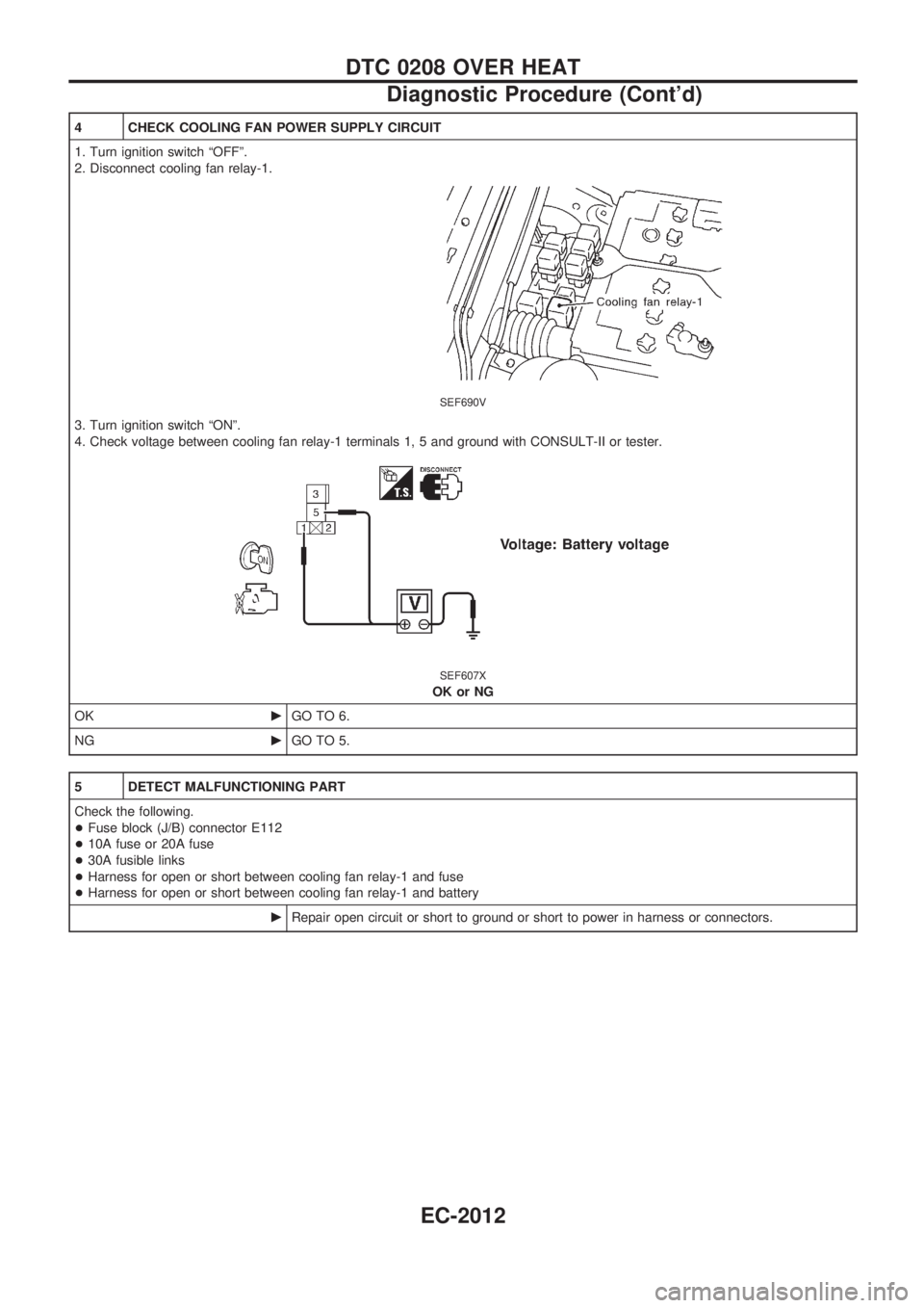
4 CHECK COOLING FAN POWER SUPPLY CIRCUIT
1. Turn ignition switch ªOFFº.
2. Disconnect cooling fan relay-1.
SEF690V
3. Turn ignition switch ªONº.
4. Check voltage between cooling fan relay-1 terminals 1, 5 and ground with CONSULT-II or tester.
SEF607X
OK or NG
OKcGO TO 6.
NGcGO TO 5.
5 DETECT MALFUNCTIONING PART
Check the following.
+Fuse block (J/B) connector E112
+10A fuse or 20A fuse
+30A fusible links
+Harness for open or short between cooling fan relay-1 and fuse
+Harness for open or short between cooling fan relay-1 and battery
cRepair open circuit or short to ground or short to power in harness or connectors.
DTC 0208 OVER HEAT
Diagnostic Procedure (Cont'd)
EC-2012
Page 50 of 273
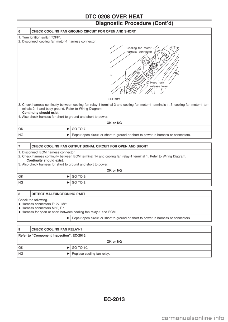
6 CHECK COOLING FAN GROUND CIRCUIT FOR OPEN AND SHORT
1. Turn ignition switch ªOFFº.
2. Disconnect cooling fan motor-1 harness connector.
SEF691V
3. Check harness continuity between cooling fan relay-1 terminal 3 and cooling fan motor-1 terminals 1, 3, cooling fan motor-1 ter-
minals 2, 4 and body ground. Refer to Wiring Diagram.
Continuity should exist.
4. Also check harness for short to ground and short to power.
OK or NG
OKcGO TO 7.
NGcRepair open circuit or short to ground or short to power in harness or connectors.
7 CHECK COOLING FAN OUTPUT SIGNAL CIRCUIT FOR OPEN AND SHORT
1. Disconnect ECM harness connector.
2. Check harness continuity between ECM terminal 14 and cooling fan relay-1 terminal 1. Refer to Wiring Diagram.
Continuity should exist.
3. Also check harness for short to ground and short to power.
OK or NG
OKcGO TO 9.
NGcGO TO 8.
8 DETECT MALFUNCTIONING PART
Check the following.
+Harness connectors E127, M21
+Harness connectors M52, F7
+Harness for open or short between cooling fan relay-1 and ECM
cRepair open circuit or short to ground or short to power in harness or connectors.
9 CHECK COOLING FAN RELAY-1
Refer to ªComponent Inspectionº, EC-2016.
OK or NG
OKcGO TO 10.
NGcReplace cooling fan relay.
DTC 0208 OVER HEAT
Diagnostic Procedure (Cont'd)
EC-2013
Page 82 of 273

Wiring Diagram Ð POWER Ð
BATTERY POWER SUPPLY Ð IGNITION SW. IN ANY POSITION
TEL373M
POWER SUPPLY ROUTING/WAGON AND HARDTOP MODELS
EL-2005
Page 86 of 273

ACCESSORY POWER SUPPLY Ð IGNITION SW. IN ªACCº OR ªONº
TEL377M
POWER SUPPLY ROUTING/WAGON AND HARDTOP MODELS
Wiring Diagram Ð POWER Ð (Cont'd)
EL-2009
Page 87 of 273

IGNITION POWER SUPPLY Ð IGNITION SW. IN ªONº AND/OR ªSTARTº
TEL378M
POWER SUPPLY ROUTING/WAGON AND HARDTOP MODELS
Wiring Diagram Ð POWER Ð (Cont'd)
EL-2010
Page 154 of 273
Electrical Components Inspection
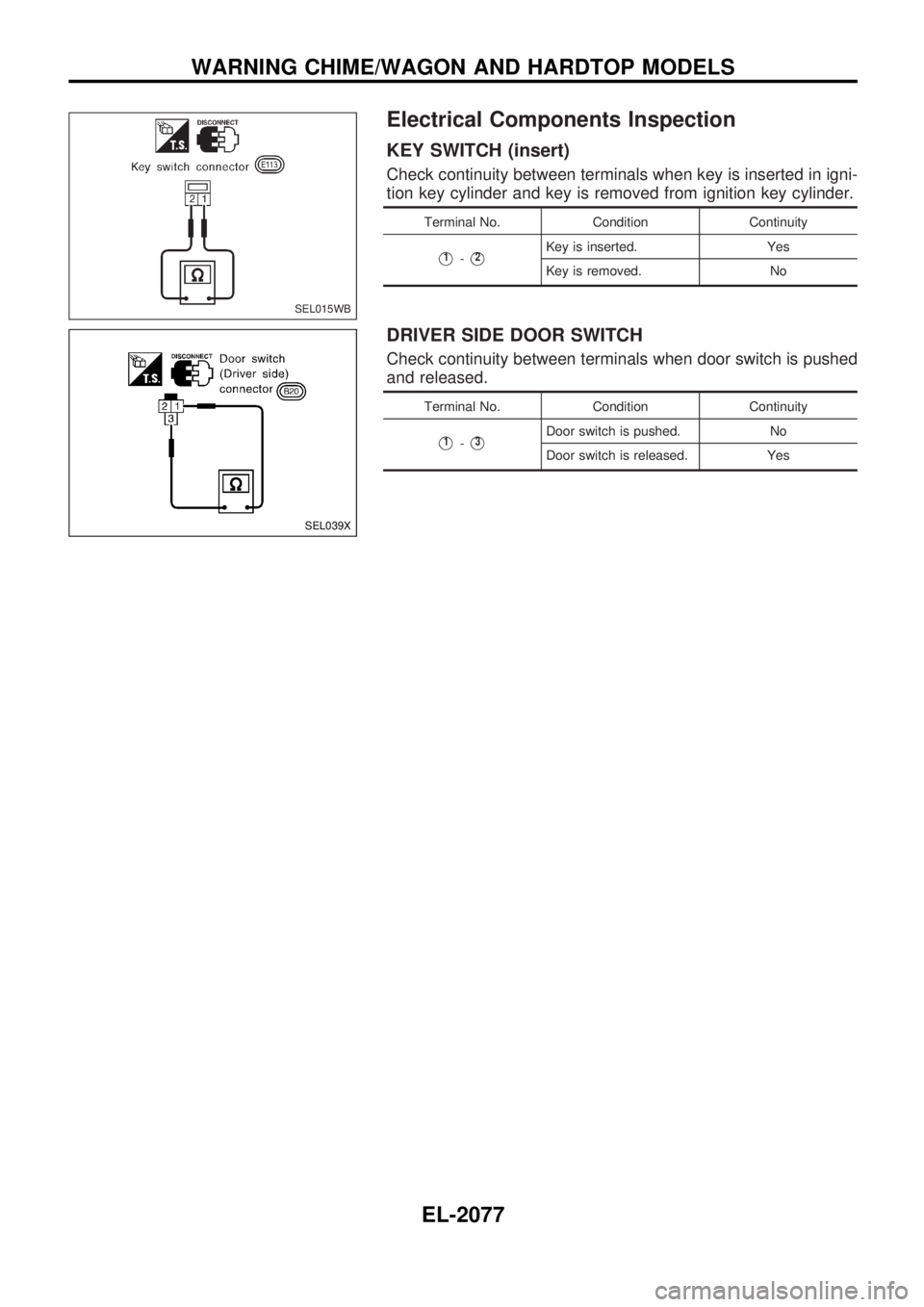
KEY SWITCH (insert)
Check continuity between terminals when key is inserted in igni-
tion key cylinder and key is removed from ignition key cylinder.
Terminal No. Condition Continuity
V1-V2Key is inserted. Yes
Key is removed. No
DRIVER SIDE DOOR SWITCH
Check continuity between terminals when door switch is pushed
and released.
Terminal No. Condition Continuity
V1-V3Door switch is pushed. No
Door switch is released. Yes
SEL015WB
SEL039X
WARNING CHIME/WAGON AND HARDTOP MODELS
EL-2077
Page 155 of 273
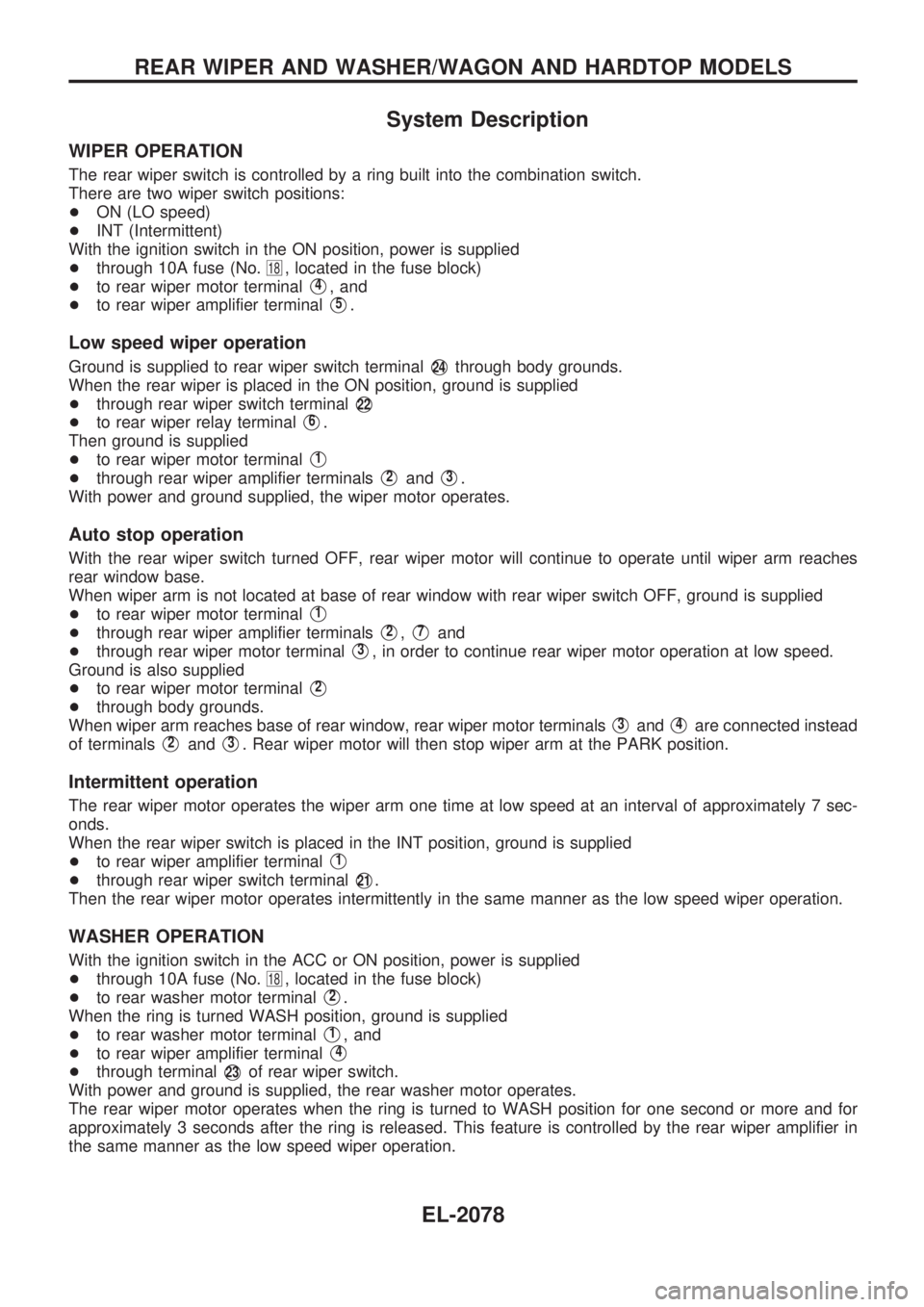
System Description
WIPER OPERATION
The rear wiper switch is controlled by a ring built into the combination switch.
There are two wiper switch positions:
+ON (LO speed)
+INT (Intermittent)
With the ignition switch in the ON position, power is supplied
+through 10A fuse (No.
18, located in the fuse block)
+to rear wiper motor terminal
V4, and
+to rear wiper amplifier terminal
V5.
Low speed wiper operation
Ground is supplied to rear wiper switch terminalV24through body grounds.
When the rear wiper is placed in the ON position, ground is supplied
+through rear wiper switch terminal
V22
+to rear wiper relay terminalV6.
Then ground is supplied
+to rear wiper motor terminal
V1
+through rear wiper amplifier terminalsV2andV3.
With power and ground supplied, the wiper motor operates.
Auto stop operation
With the rear wiper switch turned OFF, rear wiper motor will continue to operate until wiper arm reaches
rear window base.
When wiper arm is not located at base of rear window with rear wiper switch OFF, ground is supplied
+to rear wiper motor terminal
V1
+through rear wiper amplifier terminalsV2,V7and
+through rear wiper motor terminal
V3, in order to continue rear wiper motor operation at low speed.
Ground is also supplied
+to rear wiper motor terminal
V2
+through body grounds.
When wiper arm reaches base of rear window, rear wiper motor terminals
V3andV4are connected instead
of terminals
V2andV3. Rear wiper motor will then stop wiper arm at the PARK position.
Intermittent operation
The rear wiper motor operates the wiper arm one time at low speed at an interval of approximately 7 sec-
onds.
When the rear wiper switch is placed in the INT position, ground is supplied
+to rear wiper amplifier terminal
V1
+through rear wiper switch terminalV21.
Then the rear wiper motor operates intermittently in the same manner as the low speed wiper operation.
WASHER OPERATION
With the ignition switch in the ACC or ON position, power is supplied
+through 10A fuse (No.
18, located in the fuse block)
+to rear washer motor terminal
V2.
When the ring is turned WASH position, ground is supplied
+to rear washer motor terminal
V1, and
+to rear wiper amplifier terminal
V4
+through terminalV23of rear wiper switch.
With power and ground is supplied, the rear washer motor operates.
The rear wiper motor operates when the ring is turned to WASH position for one second or more and for
approximately 3 seconds after the ring is released. This feature is controlled by the rear wiper amplifier in
the same manner as the low speed wiper operation.
REAR WIPER AND WASHER/WAGON AND HARDTOP MODELS
EL-2078
Page 209 of 273
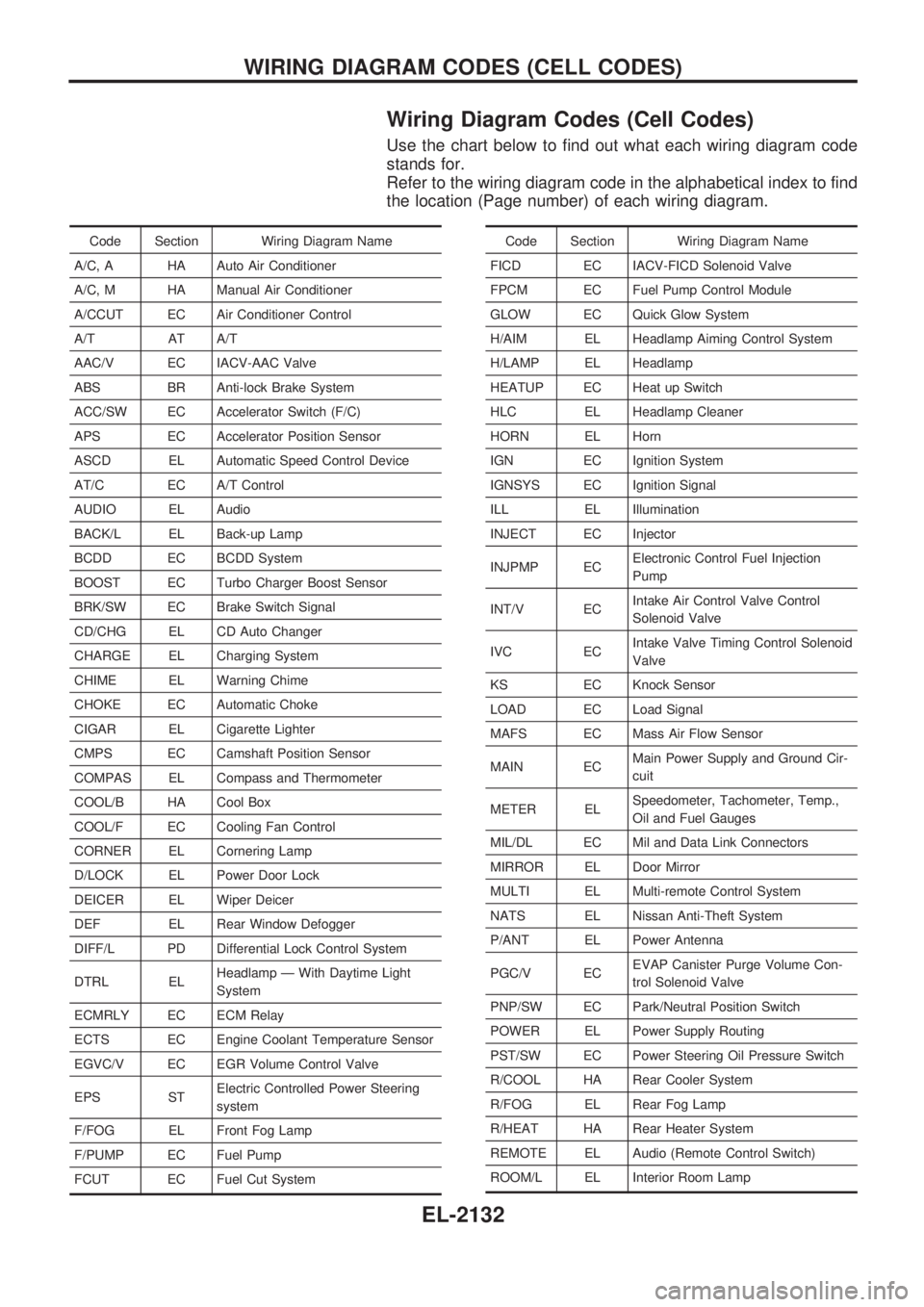
Wiring Diagram Codes (Cell Codes)
Use the chart below to find out what each wiring diagram code
stands for.
Refer to the wiring diagram code in the alphabetical index to find
the location (Page number) of each wiring diagram.
Code Section Wiring Diagram Name
A/C, A HA Auto Air Conditioner
A/C, M HA Manual Air Conditioner
A/CCUT EC Air Conditioner Control
A/T AT A/T
AAC/V EC IACV-AAC Valve
ABS BR Anti-lock Brake System
ACC/SW EC Accelerator Switch (F/C)
APS EC Accelerator Position Sensor
ASCD EL Automatic Speed Control Device
AT/C EC A/T Control
AUDIO EL Audio
BACK/L EL Back-up Lamp
BCDD EC BCDD System
BOOST EC Turbo Charger Boost Sensor
BRK/SW EC Brake Switch Signal
CD/CHG EL CD Auto Changer
CHARGE EL Charging System
CHIME EL Warning Chime
CHOKE EC Automatic Choke
CIGAR EL Cigarette Lighter
CMPS EC Camshaft Position Sensor
COMPAS EL Compass and Thermometer
COOL/B HA Cool Box
COOL/F EC Cooling Fan Control
CORNER EL Cornering Lamp
D/LOCK EL Power Door Lock
DEICER EL Wiper Deicer
DEF EL Rear Window Defogger
DIFF/L PD Differential Lock Control System
DTRL ELHeadlamp Ð With Daytime Light
System
ECMRLY EC ECM Relay
ECTS EC Engine Coolant Temperature Sensor
EGVC/V EC EGR Volume Control Valve
EPS STElectric Controlled Power Steering
system
F/FOG EL Front Fog Lamp
F/PUMP EC Fuel Pump
FCUT EC Fuel Cut SystemCode Section Wiring Diagram Name
FICD EC IACV-FICD Solenoid Valve
FPCM EC Fuel Pump Control Module
GLOW EC Quick Glow System
H/AIM EL Headlamp Aiming Control System
H/LAMP EL Headlamp
HEATUP EC Heat up Switch
HLC EL Headlamp Cleaner
HORN EL Horn
IGN EC Ignition System
IGNSYS EC Ignition Signal
ILL EL Illumination
INJECT EC Injector
INJPMP ECElectronic Control Fuel Injection
Pump
INT/V ECIntake Air Control Valve Control
Solenoid Valve
IVC ECIntake Valve Timing Control Solenoid
Valve
KS EC Knock Sensor
LOAD EC Load Signal
MAFS EC Mass Air Flow Sensor
MAIN ECMain Power Supply and Ground Cir-
cuit
METER ELSpeedometer, Tachometer, Temp.,
Oil and Fuel Gauges
MIL/DL EC Mil and Data Link Connectors
MIRROR EL Door Mirror
MULTI EL Multi-remote Control System
NATS EL Nissan Anti-Theft System
P/ANT EL Power Antenna
PGC/V ECEVAP Canister Purge Volume Con-
trol Solenoid Valve
PNP/SW EC Park/Neutral Position Switch
POWER EL Power Supply Routing
PST/SW EC Power Steering Oil Pressure Switch
R/COOL HA Rear Cooler System
R/FOG EL Rear Fog Lamp
R/HEAT HA Rear Heater System
REMOTE EL Audio (Remote Control Switch)
ROOM/L EL Interior Room Lamp
WIRING DIAGRAM CODES (CELL CODES)
EL-2132
Page 254 of 273
Precautions for SRS ªAIR BAGº and ªSEAT
BELT PRE-TENSIONERº Service
+Do not use electrical test equipment to check SRS circuits unless instructed to in this Service Manual.
+Before servicing the SRS, turn ignition switch ªOFFº, disconnect both battery cables and wait at least 3
minutes.
For approximately 3 minutes after the cables are removed, it is still possible for the air bag and seat belt
pre-tensioner to deploy. Therefore, do not work on any SRS connectors or wires until at least 3 minutes
have passed.
+Diagnosis sensor unit must always be installed with their arrow marks ª
Sº pointing towards the front of
the vehicle for proper operation. Also check diagnosis sensor unit for cracks, deformities or rust before
installation and replace as required.
+The spiral cable must be aligned with the neutral position since its rotations are limited. Do not attempt
to turn steering wheel or column after removal of steering gear.
+Handle air bag module carefully. Always place driver and passenger air bag modules with the pad side
facing upward and front side air bag modules (built-in type) with the stud bolt side facing down.
+Conduct self-diagnosis to check entire SRS for proper function after replacing any components.
+After air bag inflates, the front instrument panel assembly should be replaced if damaged.
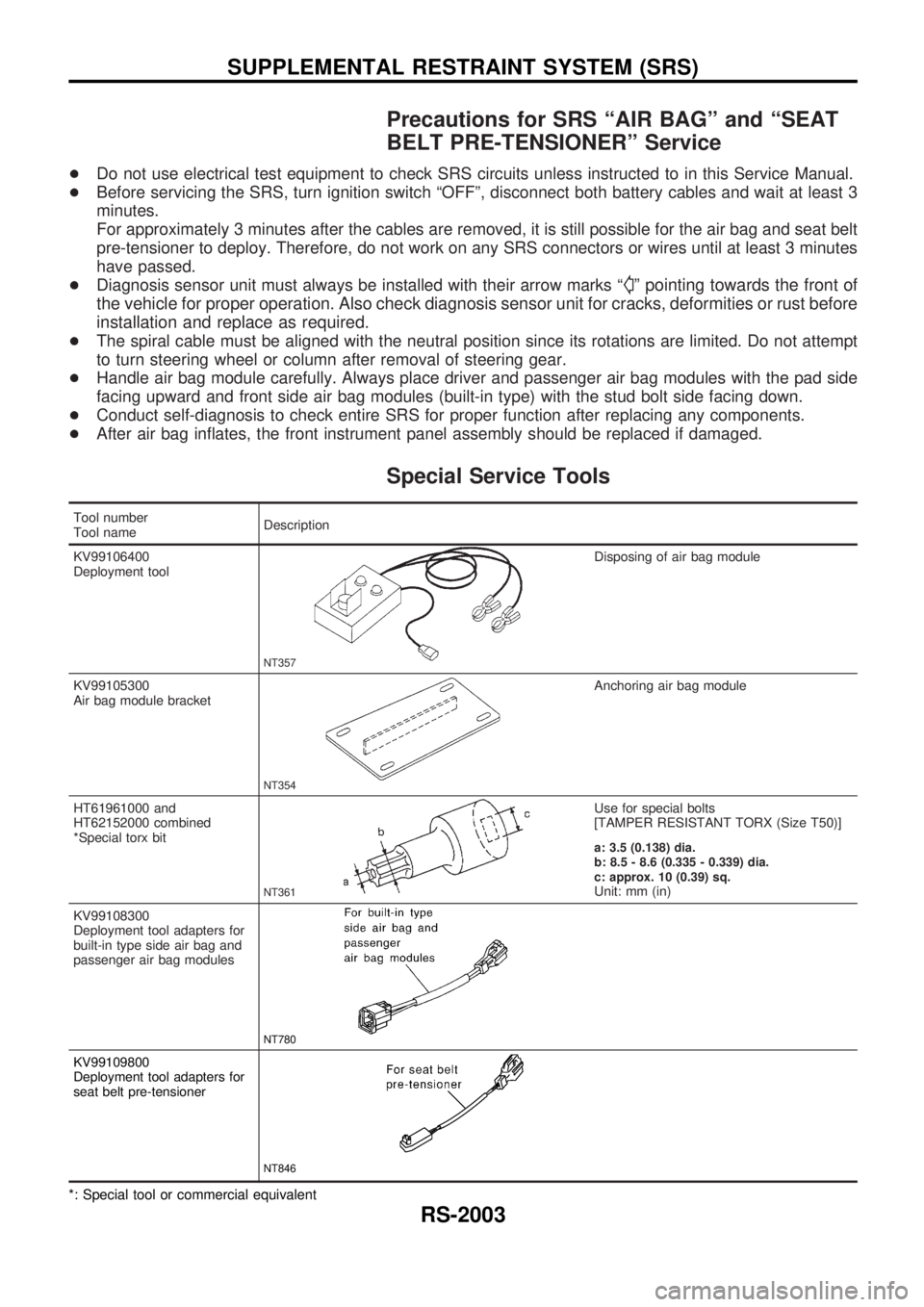
Special Service Tools
Tool number
Tool nameDescription
KV99106400
Deployment tool
NT357
Disposing of air bag module
KV99105300
Air bag module bracket
NT354
Anchoring air bag module
HT61961000 and
HT62152000 combined
*Special torx bit
NT361
Use for special bolts
[TAMPER RESISTANT TORX (Size T50)]
a: 3.5 (0.138) dia.
b: 8.5 - 8.6 (0.335 - 0.339) dia.
c: approx. 10 (0.39) sq.
Unit: mm (in)
KV99108300
Deployment tool adapters for
built-in type side air bag and
passenger air bag modules
NT780
KV99109800
Deployment tool adapters for
seat belt pre-tensioner
NT846
*: Special tool or commercial equivalent
SUPPLEMENTAL RESTRAINT SYSTEM (SRS)
RS-2003