battery NISSAN PATROL 2002 Electronic Repair Manual
[x] Cancel search | Manufacturer: NISSAN, Model Year: 2002, Model line: PATROL, Model: NISSAN PATROL 2002Pages: 311, PDF Size: 12.08 MB
Page 34 of 311
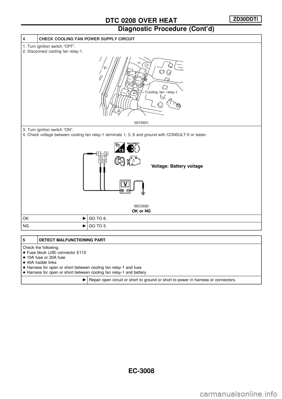
4 CHECK COOLING FAN POWER SUPPLY CIRCUIT
1. Turn ignition switch ªOFFº.
2. Disconnect cooling fan relay-1.
SEF690V
3. Turn ignition switch ªONº.
4. Check voltage between cooling fan relay-1 terminals 1, 3, 6 and ground with CONSULT-II or tester.
SEC533D
OK or NG
OKcGO TO 6.
NGcGO TO 5.
5 DETECT MALFUNCTIONING PART
Check the following.
+Fuse block (J/B) connector E112
+10A fuse or 20A fuse
+40A fusible links
+Harness for open or short between cooling fan relay-1 and fuse
+Harness for open or short between cooling fan relay-1 and battery
cRepair open circuit or short to ground or short to power in harness or connectors.
DTC 0208 OVER HEATZD30DDTi
Diagnostic Procedure (Cont'd)
EC-3008
Page 36 of 311
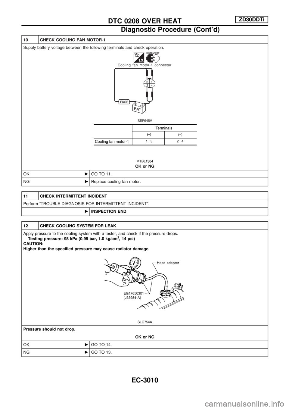
10 CHECK COOLING FAN MOTOR-1
Supply battery voltage between the following terminals and check operation.
SEF645V
MTBL1304
OK or NG
OKcGO TO 11.
NGcReplace cooling fan motor.
11 CHECK INTERMITTENT INCIDENT
Perform ªTROUBLE DIAGNOSIS FOR INTERMITTENT INCIDENTº.
cINSPECTION END
12 CHECK COOLING SYSTEM FOR LEAK
Apply pressure to the cooling system with a tester, and check if the pressure drops.
Testing pressure: 98 kPa (0.98 bar, 1.0 kg/cm
2, 14 psi)
CAUTION:
Higher than the specified pressure may cause radiator damage.
SLC754A
Pressure should not drop.
OK or NG
OKcGO TO 14.
NGcGO TO 13.
DTC 0208 OVER HEATZD30DDTi
Diagnostic Procedure (Cont'd)
EC-3010
Page 47 of 311
ELECTRICAL SYSTEM
SECTION
EL
When you read wiring diagrams:
+Read GI section, ªHOW TO READ WIRING DIAGRAMSº.
When you perform trouble diagnoses, read GI section, ªHOW TO FOLLOW FLOW
CHART IN TROUBLE DIAGNOSESº and ªHOW TO PERFORM EFFICIENT DIAGNOSIS
FOR AN ELECTRICAL INCIDENTº.
+Check for any service bulletins before servicing the vehicle.
MODIFICATION NOTICE:
+Combination meter has been changed.
+Wiring Diagram has been changed.
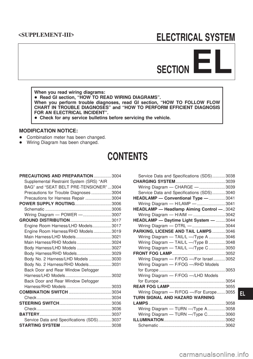
CONTENTS
PRECAUTIONS AND PREPARATION............... 3004
Supplemental Restraint System (SRS) ªAIR
BAGº and ªSEAT BELT PRE-TENSIONERº ... 3004
Precautions for Trouble Diagnoses ................. 3004
Precautions for Harness Repair ...................... 3004
POWER SUPPLY ROUTING............................... 3006
Schematic ........................................................ 3006
Wiring Diagram Ð POWER Ð ........................ 3007
GROUND DISTRIBUTION................................... 3017
Engine Room Harness/LHD Models................ 3017
Engine Room Harness/RHD Models ............... 3019
Main Harness/LHD Models .............................. 3021
Main Harness/RHD Models ............................. 3024
Body Harness/LHD Models ............................. 3027
Body Harness/RHD Models ............................. 3029
Body No. 2 Harness/LHD Models ................... 3030
Body No. 2 Harness/RHD Models ................... 3031
Back Door and Rear Window Defogger
Harness/LHD Models ....................................... 3032
Back Door and Rear Window Defogger
Harness/RHD Models ...................................... 3033
COMBINATION SWITCH.................................... 3034
Check ............................................................... 3034
STEERING SWITCH............................................ 3036
Check ............................................................... 3036
BATTERY............................................................. 3037
Service Data and Specifications (SDS) ........... 3037
STARTING SYSTEM........................................... 3038Service Data and Specifications (SDS) ........... 3038
CHARGING SYSTEM.......................................... 3039
Wiring Diagram Ð CHARGE Ð ...................... 3039
Service Data and Specifications (SDS) ........... 3040
HEADLAMP Ð Conventional Type Ð.............. 3041
Wiring Diagram Ð H/LAMP Ð ........................ 3041
HEADLAMP Ð Headlamp Aiming Control Ð.. 3042
Wiring Diagram Ð H/AIM Ð ........................... 3042
HEADLAMP Ð Daytime Light System Ð........ 3044
Wiring Diagram Ð DTRL Ð ............................ 3044
PARKING, LICENSE AND TAIL LAMPS........... 3046
Wiring Diagram Ð TAIL/L Ð/Type A .............. 3046
Wiring Diagram Ð TAIL/L Ð/Type B .............. 3048
Wiring Diagram Ð TAIL/L Ð/Type C .............. 3050
FRONT FOG LAMP............................................. 3052
Wiring Diagram Ð F/FOG Ð/For Israel .......... 3052
Wiring Diagram Ð F/FOG Ð/RHD Models
for Europe ........................................................ 3053
Wiring Diagram Ð F/FOG Ð/LHD Models
for Europe ........................................................ 3054
REAR FOG LAMP............................................... 3055
Wiring Diagram Ð R/FOG Ð/For Europe ....... 3055
TURN SIGNAL AND HAZARD WARNING
LAMPS................................................................. 3058
Wiring Diagram Ð TURN Ð/Type A ............... 3058
Wiring Diagram Ð TURN Ð/Type C............... 3060
ILLUMINATION.................................................... 3062
Schematic ........................................................ 3062
EL
Page 53 of 311

Wiring Diagram Ð POWER Ð
BATTERY POWER SUPPLY Ð IGNITION SW. IN ANY POSITION
TEL809M
POWER SUPPLY ROUTING
EL-3007
Page 83 of 311
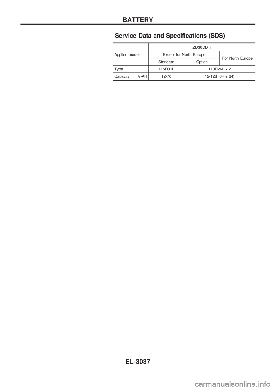
Service Data and Specifications (SDS)
Applied modelZD30DDTi
Except for North Europe
For North Europe
Standard Option
Type 115D31L 110D26L x 2
Capacity V-AH 12-70 12-128 (64 + 64)
BATTERY
EL-3037
Page 269 of 311
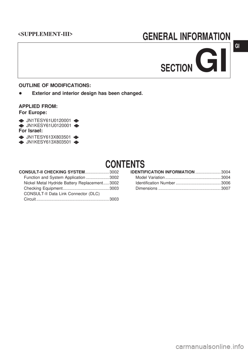
GENERAL INFORMATIONSECTION
GI
OUTLINE OF MODIFICATIONS:
+ Exterior and interior design has been changed.
APPLIED FROM: For Europe:
JN1TESY61U0120001
JN1KESY61U0120001
For Israel:
JN1TESY613X803501
JN1KESY613X803501
CONTENTS
CONSULT-II CHECKING SYSTEM ..................... 3002
Function and System Application .................... 3002
Nickel Metal Hydride Battery Replacement ..... 3002
Checking Equipment ........................................ 3003
CONSULT-II Data Link Connector (DLC)
Circuit ............................................................... 3003 IDENTIFICATION INFORMATION
...................... 3004
Model Variation ................................................ 3004
Identification Number ....................................... 3006
Dimensions ...................................................... 3007
GI
Page 270 of 311
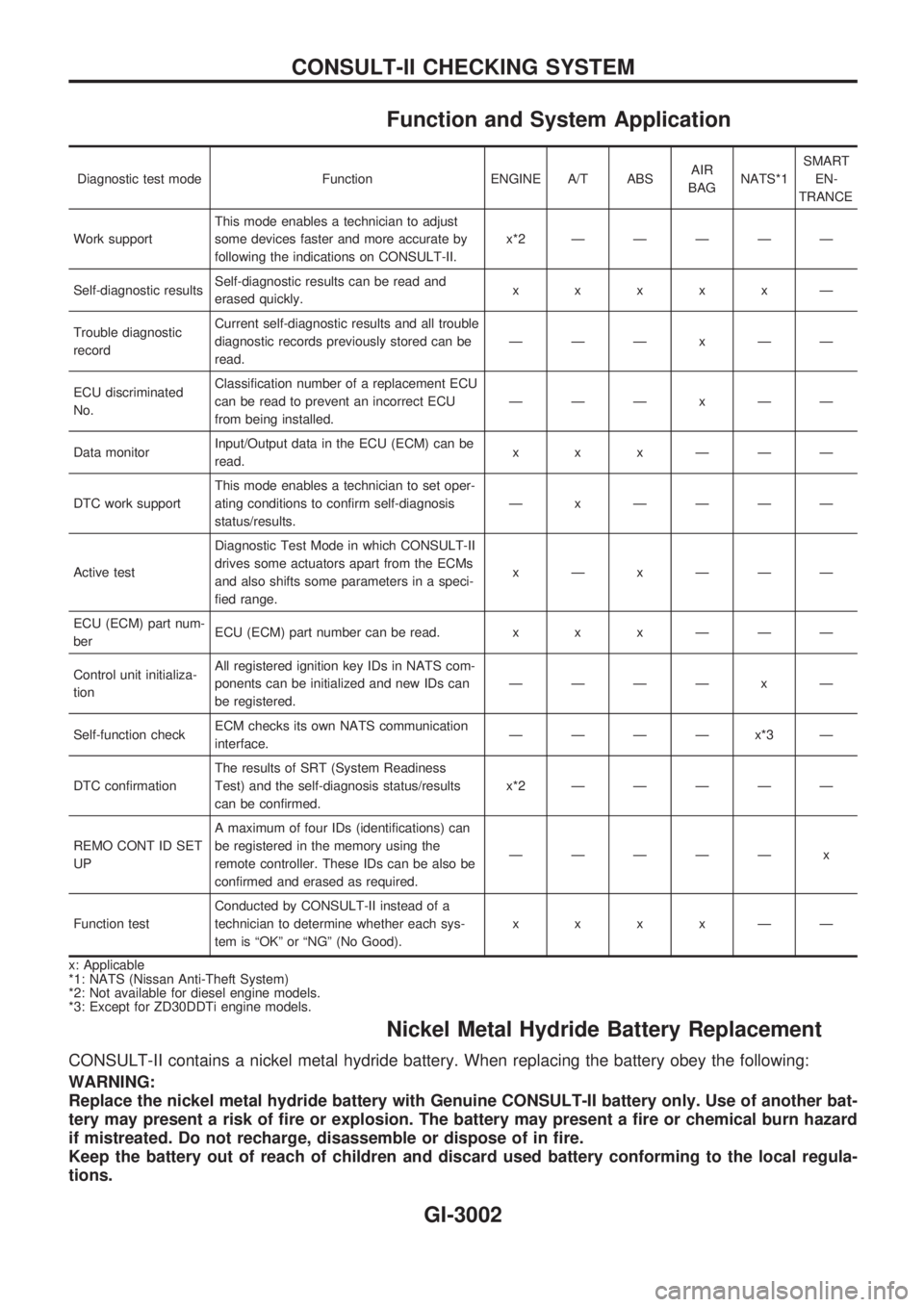
Function and System Application
Diagnostic test mode Function ENGINE A/T ABSAIR
BAGNATS*1SMART
EN-
TRANCE
Work supportThis mode enables a technician to adjust
some devices faster and more accurate by
following the indications on CONSULT-II.x*2ÐÐÐÐÐ
Self-diagnostic resultsSelf-diagnostic results can be read and
erased quickly.xxxxxÐ
Trouble diagnostic
recordCurrent self-diagnostic results and all trouble
diagnostic records previously stored can be
read.ÐÐÐxÐÐ
ECU discriminated
No.Classification number of a replacement ECU
can be read to prevent an incorrect ECU
from being installed.ÐÐÐxÐÐ
Data monitorInput/Output data in the ECU (ECM) can be
read.xxxÐÐÐ
DTC work supportThis mode enables a technician to set oper-
ating conditions to confirm self-diagnosis
status/results.Ð x ÐÐÐÐ
Active testDiagnostic Test Mode in which CONSULT-II
drives some actuators apart from the ECMs
and also shifts some parameters in a speci-
fied range.xÐxÐÐÐ
ECU (ECM) part num-
berECU (ECM) part number can be read. x x x Ð Ð Ð
Control unit initializa-
tionAll registered ignition key IDs in NATS com-
ponents can be initialized and new IDs can
be registered.ÐÐÐÐ x Ð
Self-function checkECM checks its own NATS communication
interface.ÐÐÐÐx*3Ð
DTC confirmationThe results of SRT (System Readiness
Test) and the self-diagnosis status/results
can be confirmed.x*2ÐÐÐÐÐ
REMO CONT ID SET
UPA maximum of four IDs (identifications) can
be registered in the memory using the
remote controller. These IDs can be also be
confirmed and erased as required.ÐÐÐÐÐ x
Function testConducted by CONSULT-II instead of a
technician to determine whether each sys-
tem is ªOKº or ªNGº (No Good).xxxxÐÐ
x: Applicable
*1: NATS (Nissan Anti-Theft System)
*2: Not available for diesel engine models.
*3: Except for ZD30DDTi engine models.
Nickel Metal Hydride Battery Replacement
CONSULT-II contains a nickel metal hydride battery. When replacing the battery obey the following:
WARNING:
Replace the nickel metal hydride battery with Genuine CONSULT-II battery only. Use of another bat-
tery may present a risk of fire or explosion. The battery may present a fire or chemical burn hazard
if mistreated. Do not recharge, disassemble or dispose of in fire.
Keep the battery out of reach of children and discard used battery conforming to the local regula-
tions.
CONSULT-II CHECKING SYSTEM
GI-3002
Page 288 of 311
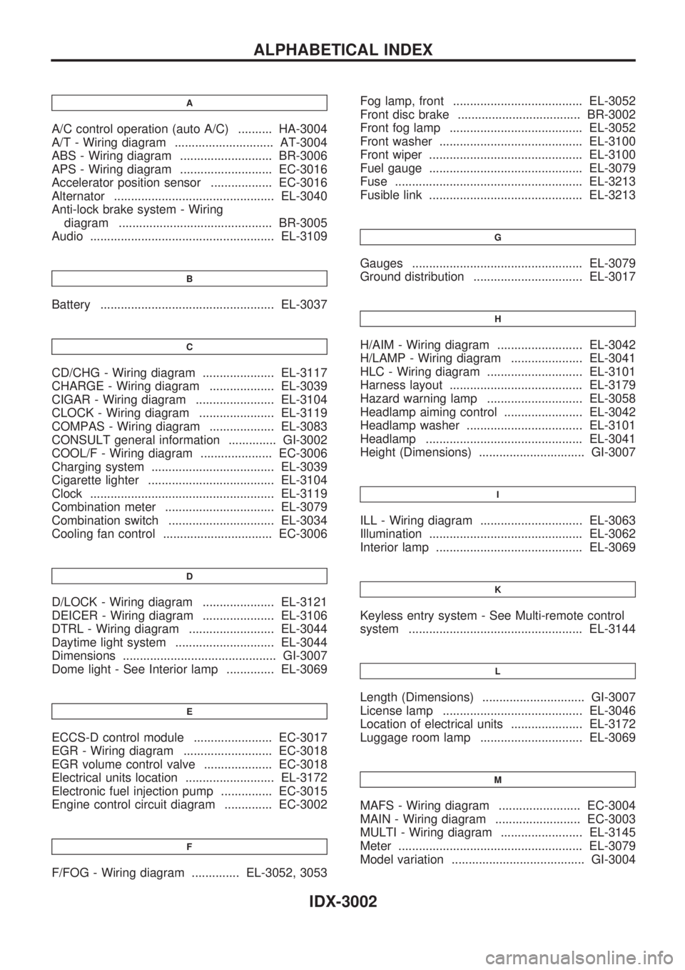
A
A/C control operation (auto A/C) .......... HA-3004
A/T - Wiring diagram ............................. AT-3004
ABS - Wiring diagram ........................... BR-3006
APS - Wiring diagram ........................... EC-3016
Accelerator position sensor .................. EC-3016
Alternator ............................................... EL-3040
Anti-lock brake system - Wiring
diagram ............................................. BR-3005
Audio ...................................................... EL-3109
B
Battery ................................................... EL-3037
C
CD/CHG - Wiring diagram ..................... EL-3117
CHARGE - Wiring diagram ................... EL-3039
CIGAR - Wiring diagram ....................... EL-3104
CLOCK - Wiring diagram ...................... EL-3119
COMPAS - Wiring diagram ................... EL-3083
CONSULT general information .............. GI-3002
COOL/F - Wiring diagram ..................... EC-3006
Charging system .................................... EL-3039
Cigarette lighter ..................................... EL-3104
Clock ...................................................... EL-3119
Combination meter ................................ EL-3079
Combination switch ............................... EL-3034
Cooling fan control ................................ EC-3006
D
D/LOCK - Wiring diagram ..................... EL-3121
DEICER - Wiring diagram ..................... EL-3106
DTRL - Wiring diagram ......................... EL-3044
Daytime light system ............................. EL-3044
Dimensions ............................................. GI-3007
Dome light - See Interior lamp .............. EL-3069
E
ECCS-D control module ....................... EC-3017
EGR - Wiring diagram .......................... EC-3018
EGR volume control valve .................... EC-3018
Electrical units location .......................... EL-3172
Electronic fuel injection pump ............... EC-3015
Engine control circuit diagram .............. EC-3002
F
F/FOG - Wiring diagram .............. EL-3052, 3053Fog lamp, front ...................................... EL-3052
Front disc brake .................................... BR-3002
Front fog lamp ....................................... EL-3052
Front washer .......................................... EL-3100
Front wiper ............................................. EL-3100
Fuel gauge ............................................. EL-3079
Fuse ....................................................... EL-3213
Fusible link ............................................. EL-3213
G
Gauges .................................................. EL-3079
Ground distribution ................................ EL-3017
H
H/AIM - Wiring diagram ......................... EL-3042
H/LAMP - Wiring diagram ..................... EL-3041
HLC - Wiring diagram ............................ EL-3101
Harness layout ....................................... EL-3179
Hazard warning lamp ............................ EL-3058
Headlamp aiming control ....................... EL-3042
Headlamp washer .................................. EL-3101
Headlamp .............................................. EL-3041
Height (Dimensions) ............................... GI-3007
I
ILL - Wiring diagram .............................. EL-3063
Illumination ............................................. EL-3062
Interior lamp ........................................... EL-3069
K
Keyless entry system - See Multi-remote control
system ................................................... EL-3144
L
Length (Dimensions) .............................. GI-3007
License lamp ......................................... EL-3046
Location of electrical units ..................... EL-3172
Luggage room lamp .............................. EL-3069
M
MAFS - Wiring diagram ........................ EC-3004
MAIN - Wiring diagram ......................... EC-3003
MULTI - Wiring diagram ........................ EL-3145
Meter ...................................................... EL-3079
Model variation ....................................... GI-3004
ALPHABETICAL INDEX
IDX-3002