engine oil NISSAN PATROL 2002 Electronic Repair Manual
[x] Cancel search | Manufacturer: NISSAN, Model Year: 2002, Model line: PATROL, Model: NISSAN PATROL 2002Pages: 311, PDF Size: 12.08 MB
Page 257 of 311

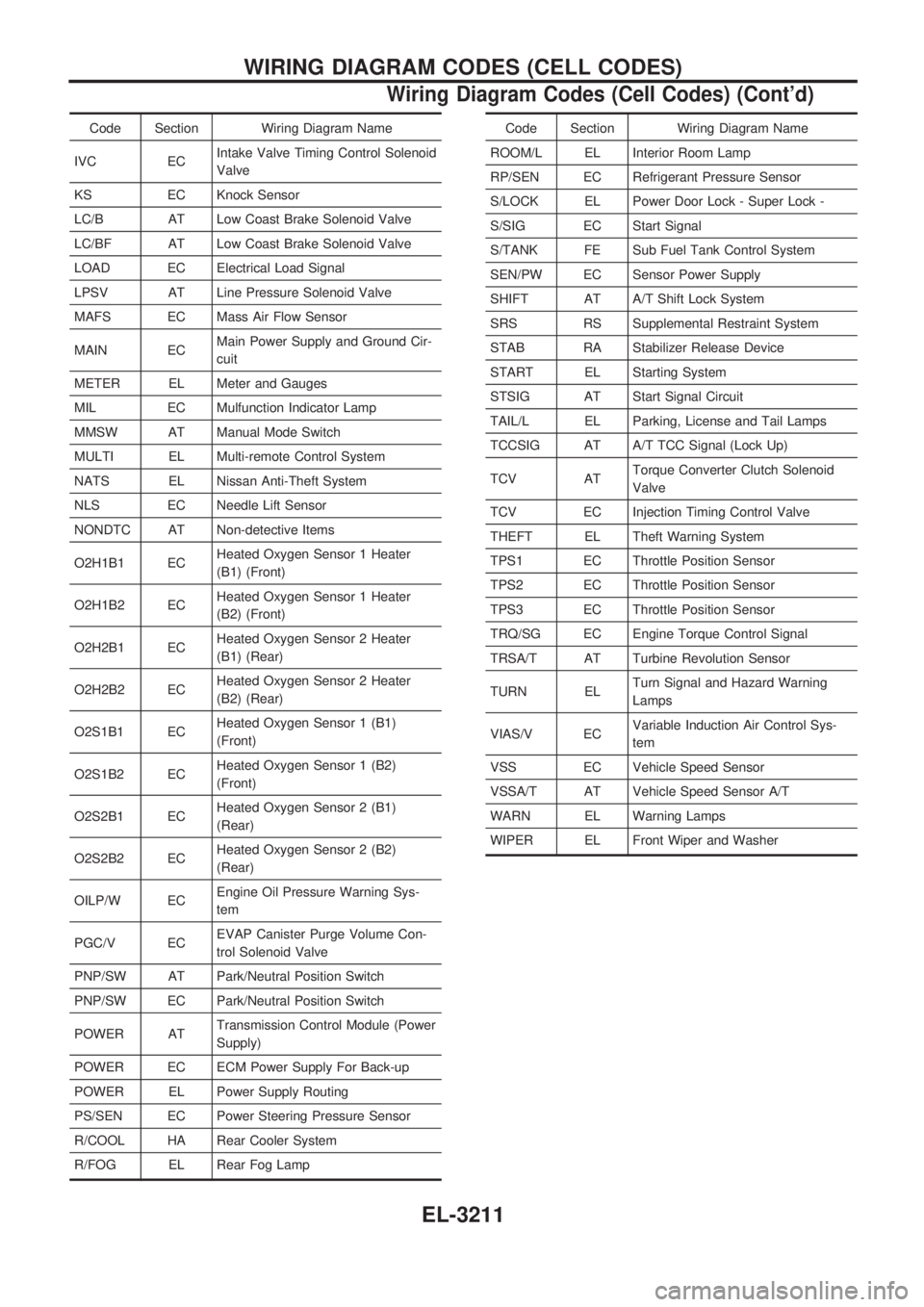
Code Section Wiring Diagram Name
IVC ECIntake Valve Timing Control Solenoid
Valve
KS EC Knock Sensor
LC/B AT Low Coast Brake Solenoid Valve
LC/BF AT Low Coast Brake Solenoid Valve
LOAD EC Electrical Load Signal
LPSV AT Line Pressure Solenoid Valve
MAFS EC Mass Air Flow Sensor
MAIN ECMain Power Supply and Ground Cir-
cuit
METER EL Meter and Gauges
MIL EC Mulfunction Indicator Lamp
MMSW AT Manual Mode Switch
MULTI EL Multi-remote Control System
NATS EL Nissan Anti-Theft System
NLS EC Needle Lift Sensor
NONDTC AT Non-detective Items
O2H1B1 ECHeated Oxygen Sensor 1 Heater
(B1) (Front)
O2H1B2 ECHeated Oxygen Sensor 1 Heater
(B2) (Front)
O2H2B1 ECHeated Oxygen Sensor 2 Heater
(B1) (Rear)
O2H2B2 ECHeated Oxygen Sensor 2 Heater
(B2) (Rear)
O2S1B1 ECHeated Oxygen Sensor 1 (B1)
(Front)
O2S1B2 ECHeated Oxygen Sensor 1 (B2)
(Front)
O2S2B1 ECHeated Oxygen Sensor 2 (B1)
(Rear)
O2S2B2 ECHeated Oxygen Sensor 2 (B2)
(Rear)
OILP/W ECEngine Oil Pressure Warning Sys-
tem
PGC/V ECEVAP Canister Purge Volume Con-
trol Solenoid Valve
PNP/SW AT Park/Neutral Position Switch
PNP/SW EC Park/Neutral Position Switch
POWER ATTransmission Control Module (Power
Supply)
POWER EC ECM Power Supply For Back-up
POWER EL Power Supply Routing
PS/SEN EC Power Steering Pressure Sensor
R/COOL HA Rear Cooler System
R/FOG EL Rear Fog LampCode Section Wiring Diagram Name
ROOM/L EL Interior Room Lamp
RP/SEN EC Refrigerant Pressure Sensor
S/LOCK EL Power Door Lock - Super Lock -
S/SIG EC Start Signal
S/TANK FE Sub Fuel Tank Control System
SEN/PW EC Sensor Power Supply
SHIFT AT A/T Shift Lock System
SRS RS Supplemental Restraint System
STAB RA Stabilizer Release Device
START EL Starting System
STSIG AT Start Signal Circuit
TAIL/L EL Parking, License and Tail Lamps
TCCSIG AT A/T TCC Signal (Lock Up)
TCV ATTorque Converter Clutch Solenoid
Valve
TCV EC Injection Timing Control Valve
THEFT EL Theft Warning System
TPS1 EC Throttle Position Sensor
TPS2 EC Throttle Position Sensor
TPS3 EC Throttle Position Sensor
TRQ/SG EC Engine Torque Control Signal
TRSA/T AT Turbine Revolution Sensor
TURN ELTurn Signal and Hazard Warning
Lamps
VIAS/V ECVariable Induction Air Control Sys-
tem
VSS EC Vehicle Speed Sensor
VSSA/T AT Vehicle Speed Sensor A/T
WARN EL Warning Lamps
WIPER EL Front Wiper and Washer
WIRING DIAGRAM CODES (CELL CODES)
Wiring Diagram Codes (Cell Codes) (Cont'd)
EL-3211
Page 294 of 311

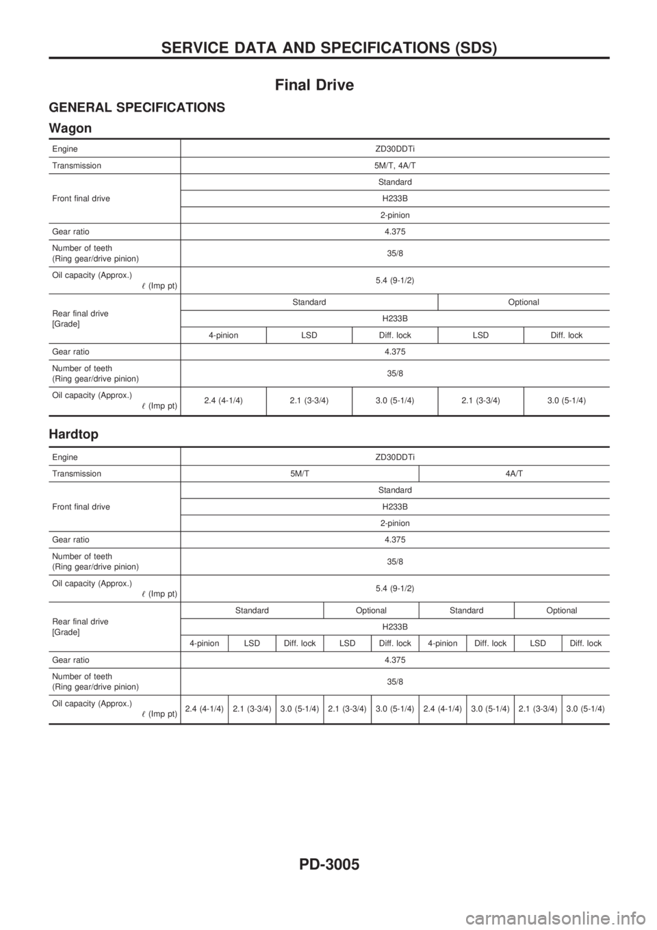
Final Drive
GENERAL SPECIFICATIONS
Wagon
EngineZD30DDTi
Transmission5M/T, 4A/T
Front final driveStandard
H233B
2-pinion
Gear ratio4.375
Number of teeth
(Ring gear/drive pinion)35/8
Oil capacity (Approx.)
!(Imp pt)5.4 (9-1/2)
Rear final drive
[Grade]Standard Optional
H233B
4-pinion LSD Diff. lock LSD Diff. lock
Gear ratio4.375
Number of teeth
(Ring gear/drive pinion)35/8
Oil capacity (Approx.)
!(Imp pt)2.4 (4-1/4) 2.1 (3-3/4) 3.0 (5-1/4) 2.1 (3-3/4) 3.0 (5-1/4)
Hardtop
EngineZD30DDTi
Transmission 5M/T 4A/T
Front final driveStandard
H233B
2-pinion
Gear ratio4.375
Number of teeth
(Ring gear/drive pinion)35/8
Oil capacity (Approx.)
!(Imp pt)5.4 (9-1/2)
Rear final drive
[Grade]Standard Optional Standard Optional
H233B
4-pinion LSD Diff. lock LSD Diff. lock 4-pinion Diff. lock LSD Diff. lock
Gear ratio4.375
Number of teeth
(Ring gear/drive pinion)35/8
Oil capacity (Approx.)
!(Imp pt)2.4 (4-1/4) 2.1 (3-3/4) 3.0 (5-1/4) 2.1 (3-3/4) 3.0 (5-1/4) 2.4 (4-1/4) 3.0 (5-1/4) 2.1 (3-3/4) 3.0 (5-1/4)
SERVICE DATA AND SPECIFICATIONS (SDS)
PD-3005