ignition NISSAN PATROL 2002 Electronic Repair Manual
[x] Cancel search | Manufacturer: NISSAN, Model Year: 2002, Model line: PATROL, Model: NISSAN PATROL 2002Pages: 311, PDF Size: 12.08 MB
Page 33 of 311
Diagnostic Procedure
1 INSPECTION START
Do you have CONSULT-II?
Yes or No
YescGO TO 2.
NocGO TO 3.
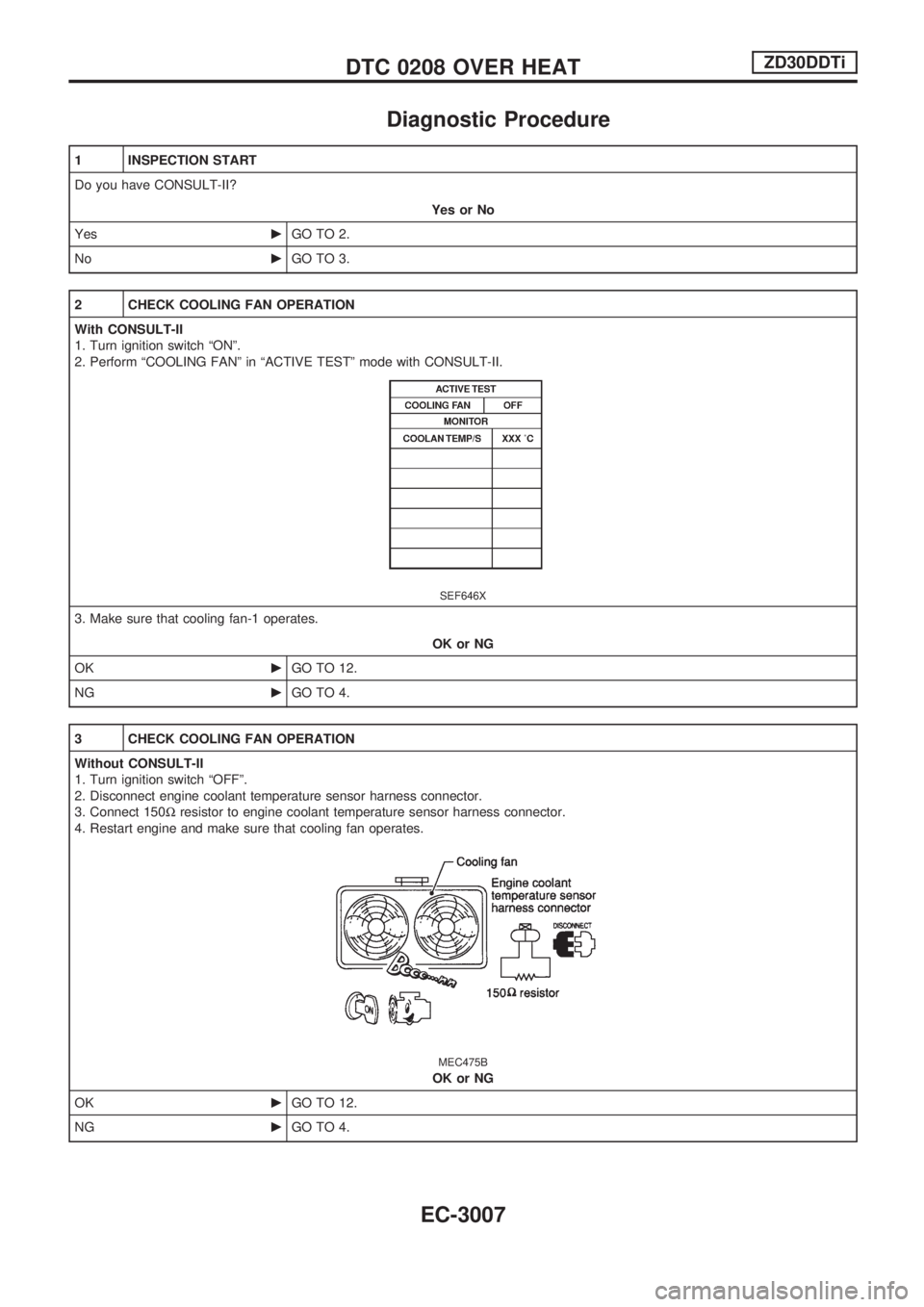
2 CHECK COOLING FAN OPERATION
With CONSULT-II
1. Turn ignition switch ªONº.
2. Perform ªCOOLING FANº in ªACTIVE TESTº mode with CONSULT-II.
SEF646X
3. Make sure that cooling fan-1 operates.
OK or NG
OKcGO TO 12.
NGcGO TO 4.
3 CHECK COOLING FAN OPERATION
Without CONSULT-II
1. Turn ignition switch ªOFFº.
2. Disconnect engine coolant temperature sensor harness connector.
3. Connect 150Wresistor to engine coolant temperature sensor harness connector.
4. Restart engine and make sure that cooling fan operates.
MEC475B
OK or NG
OKcGO TO 12.
NGcGO TO 4.
DTC 0208 OVER HEATZD30DDTi
EC-3007
Page 34 of 311
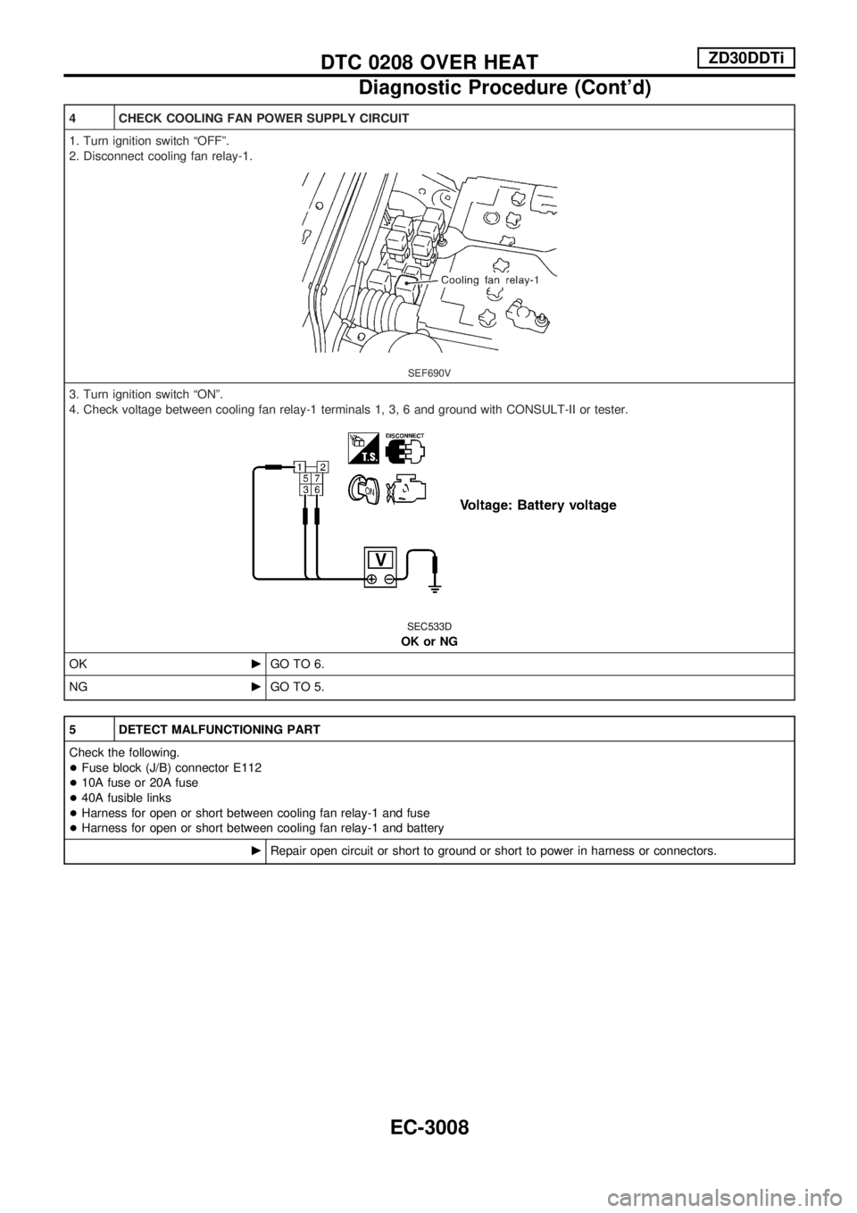
4 CHECK COOLING FAN POWER SUPPLY CIRCUIT
1. Turn ignition switch ªOFFº.
2. Disconnect cooling fan relay-1.
SEF690V
3. Turn ignition switch ªONº.
4. Check voltage between cooling fan relay-1 terminals 1, 3, 6 and ground with CONSULT-II or tester.
SEC533D
OK or NG
OKcGO TO 6.
NGcGO TO 5.
5 DETECT MALFUNCTIONING PART
Check the following.
+Fuse block (J/B) connector E112
+10A fuse or 20A fuse
+40A fusible links
+Harness for open or short between cooling fan relay-1 and fuse
+Harness for open or short between cooling fan relay-1 and battery
cRepair open circuit or short to ground or short to power in harness or connectors.
DTC 0208 OVER HEATZD30DDTi
Diagnostic Procedure (Cont'd)
EC-3008
Page 35 of 311
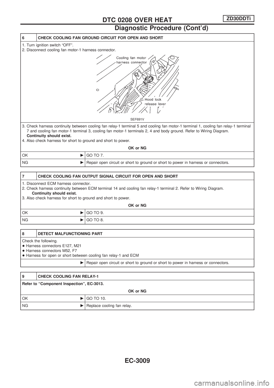
6 CHECK COOLING FAN GROUND CIRCUIT FOR OPEN AND SHORT
1. Turn ignition switch ªOFFº.
2. Disconnect cooling fan motor-1 harness connector.
SEF691V
3. Check harness continuity between cooling fan relay-1 terminal 5 and cooling fan motor-1 terminal 1, cooling fan relay-1 terminal
7 and cooling fan motor-1 terminal 3, cooling fan motor-1 terminals 2, 4 and body ground. Refer to Wiring Diagram.
Continuity should exist.
4. Also check harness for short to ground and short to power.
OK or NG
OKcGO TO 7.
NGcRepair open circuit or short to ground or short to power in harness or connectors.
7 CHECK COOLING FAN OUTPUT SIGNAL CIRCUIT FOR OPEN AND SHORT
1. Disconnect ECM harness connector.
2. Check harness continuity between ECM terminal 14 and cooling fan relay-1 terminal 2. Refer to Wiring Diagram.
Continuity should exist.
3. Also check harness for short to ground and short to power.
OK or NG
OKcGO TO 9.
NGcGO TO 8.
8 DETECT MALFUNCTIONING PART
Check the following.
+Harness connectors E127, M21
+Harness connectors M52, F7
+Harness for open or short between cooling fan relay-1 and ECM
cRepair open circuit or short to ground or short to power in harness or connectors.
9 CHECK COOLING FAN RELAY-1
Refer to ªComponent Inspectionº, EC-3013.
OK or NG
OKcGO TO 10.
NGcReplace cooling fan relay.
DTC 0208 OVER HEATZD30DDTi
Diagnostic Procedure (Cont'd)
EC-3009
Page 53 of 311

Wiring Diagram Ð POWER Ð
BATTERY POWER SUPPLY Ð IGNITION SW. IN ANY POSITION
TEL809M
POWER SUPPLY ROUTING
EL-3007
Page 58 of 311

ACCESSORY POWER SUPPLY Ð IGNITION SW. IN ªACCº OR ªONº
TEL647M
POWER SUPPLY ROUTING
Wiring Diagram Ð POWER Ð (Cont'd)
EL-3012
Page 59 of 311

IGNITION POWER SUPPLY Ð IGNITION SW. IN ªONº AND/OR ªSTARTº
TEL749M
POWER SUPPLY ROUTING
Wiring Diagram Ð POWER Ð (Cont'd)
EL-3013
Page 256 of 311
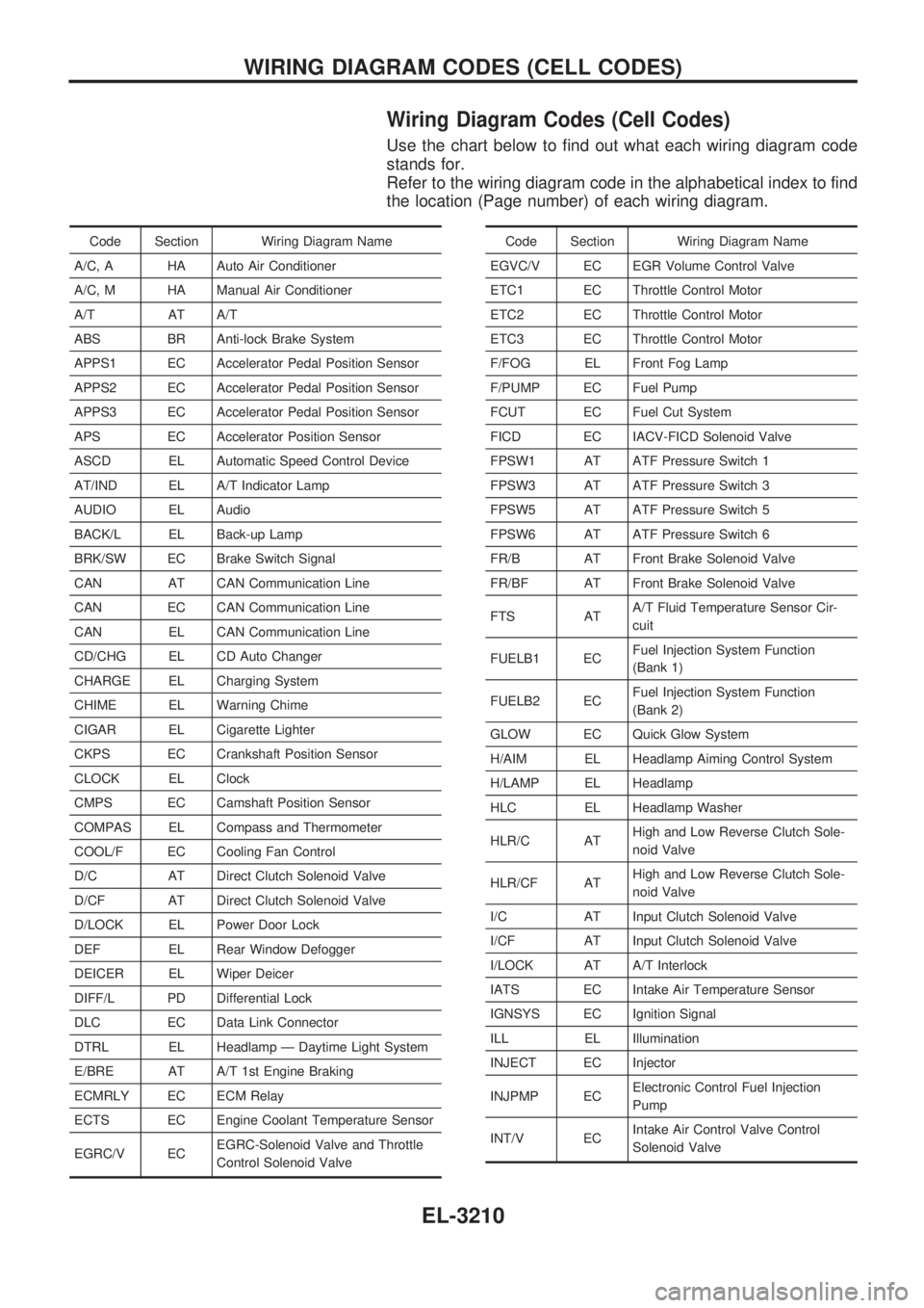
Wiring Diagram Codes (Cell Codes)
Use the chart below to find out what each wiring diagram code
stands for.
Refer to the wiring diagram code in the alphabetical index to find
the location (Page number) of each wiring diagram.
Code Section Wiring Diagram Name
A/C, A HA Auto Air Conditioner
A/C, M HA Manual Air Conditioner
A/T AT A/T
ABS BR Anti-lock Brake System
APPS1 EC Accelerator Pedal Position Sensor
APPS2 EC Accelerator Pedal Position Sensor
APPS3 EC Accelerator Pedal Position Sensor
APS EC Accelerator Position Sensor
ASCD EL Automatic Speed Control Device
AT/IND EL A/T Indicator Lamp
AUDIO EL Audio
BACK/L EL Back-up Lamp
BRK/SW EC Brake Switch Signal
CAN AT CAN Communication Line
CAN EC CAN Communication Line
CAN EL CAN Communication Line
CD/CHG EL CD Auto Changer
CHARGE EL Charging System
CHIME EL Warning Chime
CIGAR EL Cigarette Lighter
CKPS EC Crankshaft Position Sensor
CLOCK EL Clock
CMPS EC Camshaft Position Sensor
COMPAS EL Compass and Thermometer
COOL/F EC Cooling Fan Control
D/C AT Direct Clutch Solenoid Valve
D/CF AT Direct Clutch Solenoid Valve
D/LOCK EL Power Door Lock
DEF EL Rear Window Defogger
DEICER EL Wiper Deicer
DIFF/L PD Differential Lock
DLC EC Data Link Connector
DTRL EL Headlamp Ð Daytime Light System
E/BRE AT A/T 1st Engine Braking
ECMRLY EC ECM Relay
ECTS EC Engine Coolant Temperature Sensor
EGRC/V ECEGRC-Solenoid Valve and Throttle
Control Solenoid ValveCode Section Wiring Diagram Name
EGVC/V EC EGR Volume Control Valve
ETC1 EC Throttle Control Motor
ETC2 EC Throttle Control Motor
ETC3 EC Throttle Control Motor
F/FOG EL Front Fog Lamp
F/PUMP EC Fuel Pump
FCUT EC Fuel Cut System
FICD EC IACV-FICD Solenoid Valve
FPSW1 AT ATF Pressure Switch 1
FPSW3 AT ATF Pressure Switch 3
FPSW5 AT ATF Pressure Switch 5
FPSW6 AT ATF Pressure Switch 6
FR/B AT Front Brake Solenoid Valve
FR/BF AT Front Brake Solenoid Valve
FTS ATA/T Fluid Temperature Sensor Cir-
cuit
FUELB1 ECFuel Injection System Function
(Bank 1)
FUELB2 ECFuel Injection System Function
(Bank 2)
GLOW EC Quick Glow System
H/AIM EL Headlamp Aiming Control System
H/LAMP EL Headlamp
HLC EL Headlamp Washer
HLR/C ATHigh and Low Reverse Clutch Sole-
noid Valve
HLR/CF ATHigh and Low Reverse Clutch Sole-
noid Valve
I/C AT Input Clutch Solenoid Valve
I/CF AT Input Clutch Solenoid Valve
I/LOCK AT A/T Interlock
IATS EC Intake Air Temperature Sensor
IGNSYS EC Ignition Signal
ILL EL Illumination
INJECT EC Injector
INJPMP ECElectronic Control Fuel Injection
Pump
INT/V ECIntake Air Control Valve Control
Solenoid Valve
WIRING DIAGRAM CODES (CELL CODES)
EL-3210
Page 260 of 311
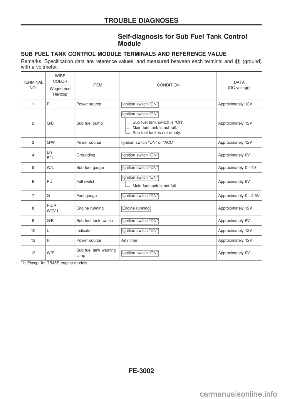
Self-diagnosis for Sub Fuel Tank Control
Module
SUB FUEL TANK CONTROL MODULE TERMINALS AND REFERENCE VALUE
Remarks: Specification data are reference values, and measured between each terminal andV11(ground)
with a voltmeter.
TERMINAL
NO.WIRE
COLOR
ITEM CONDITIONDATA
(DC voltage)
Wagon and
Hardtop
1 R Power source Ignition switch ªONº
Approximately 12V
2 G/B Sub fuel pumpIgnition switch ªONº
Sub fuel tank switch is ªONº.
Main fuel tank is not full.
Sub fuel tank is not empty.Approximately 12V
3 G/W Power source Ignition switch ªONº or ªACCº Approximately 12V
4L/Y
B*1Grounding Ignition switch ªONº
Approximately 0V
5 W/L Sub fuel gauge Ignition switch ªONº
Approximately0-4V
6 PU Full switchIgnition switch ªONº
Main fuel tank is not full.Approximately 5V
7 G Fuel gauge Ignition switch ªONº
Approximately 0 - 2.5V
8PU/R
W/G*1Engine running Engine running
Approximately 12V
9 G/B Sub fuel tank switch Ignition switch ªONº
Approximately 5V
10 L Indicator Ignition switch ªONº
Approximately 12V
12 R Power source Any time Approximately 12V
13 W/RSub fuel tank warning
lampIgnition switch ªONº
Approximately 0V
*1: Except for TB45S engine models
TROUBLE DIAGNOSES
FE-3002
Page 270 of 311
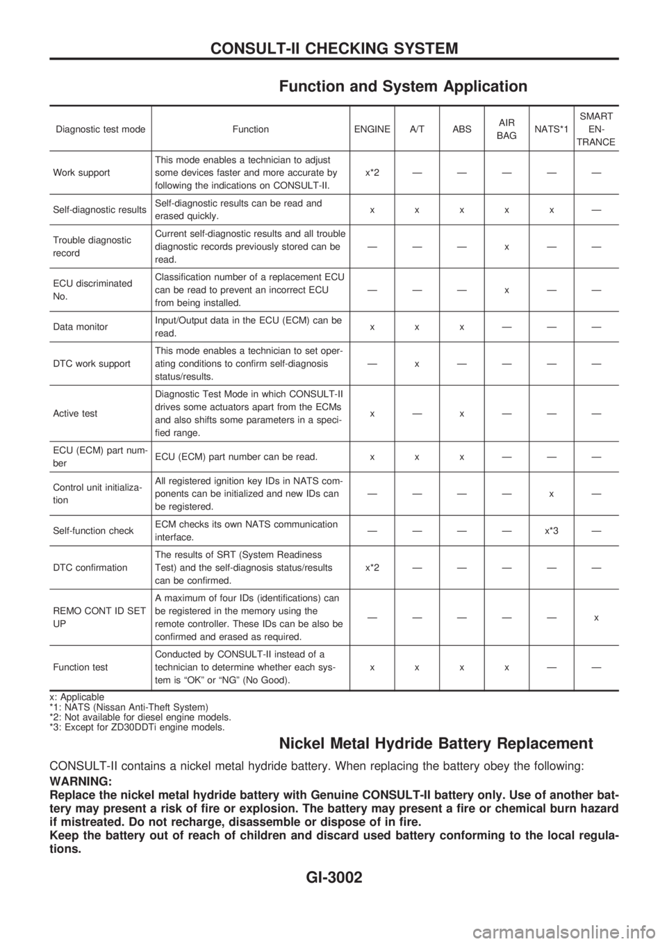
Function and System Application
Diagnostic test mode Function ENGINE A/T ABSAIR
BAGNATS*1SMART
EN-
TRANCE
Work supportThis mode enables a technician to adjust
some devices faster and more accurate by
following the indications on CONSULT-II.x*2ÐÐÐÐÐ
Self-diagnostic resultsSelf-diagnostic results can be read and
erased quickly.xxxxxÐ
Trouble diagnostic
recordCurrent self-diagnostic results and all trouble
diagnostic records previously stored can be
read.ÐÐÐxÐÐ
ECU discriminated
No.Classification number of a replacement ECU
can be read to prevent an incorrect ECU
from being installed.ÐÐÐxÐÐ
Data monitorInput/Output data in the ECU (ECM) can be
read.xxxÐÐÐ
DTC work supportThis mode enables a technician to set oper-
ating conditions to confirm self-diagnosis
status/results.Ð x ÐÐÐÐ
Active testDiagnostic Test Mode in which CONSULT-II
drives some actuators apart from the ECMs
and also shifts some parameters in a speci-
fied range.xÐxÐÐÐ
ECU (ECM) part num-
berECU (ECM) part number can be read. x x x Ð Ð Ð
Control unit initializa-
tionAll registered ignition key IDs in NATS com-
ponents can be initialized and new IDs can
be registered.ÐÐÐÐ x Ð
Self-function checkECM checks its own NATS communication
interface.ÐÐÐÐx*3Ð
DTC confirmationThe results of SRT (System Readiness
Test) and the self-diagnosis status/results
can be confirmed.x*2ÐÐÐÐÐ
REMO CONT ID SET
UPA maximum of four IDs (identifications) can
be registered in the memory using the
remote controller. These IDs can be also be
confirmed and erased as required.ÐÐÐÐÐ x
Function testConducted by CONSULT-II instead of a
technician to determine whether each sys-
tem is ªOKº or ªNGº (No Good).xxxxÐÐ
x: Applicable
*1: NATS (Nissan Anti-Theft System)
*2: Not available for diesel engine models.
*3: Except for ZD30DDTi engine models.
Nickel Metal Hydride Battery Replacement
CONSULT-II contains a nickel metal hydride battery. When replacing the battery obey the following:
WARNING:
Replace the nickel metal hydride battery with Genuine CONSULT-II battery only. Use of another bat-
tery may present a risk of fire or explosion. The battery may present a fire or chemical burn hazard
if mistreated. Do not recharge, disassemble or dispose of in fire.
Keep the battery out of reach of children and discard used battery conforming to the local regula-
tions.
CONSULT-II CHECKING SYSTEM
GI-3002