Lamp NISSAN PATROL 2004 Electronic Manual PDF
[x] Cancel search | Manufacturer: NISSAN, Model Year: 2004, Model line: PATROL, Model: NISSAN PATROL 2004Pages: 579, PDF Size: 26.61 MB
Page 302 of 579
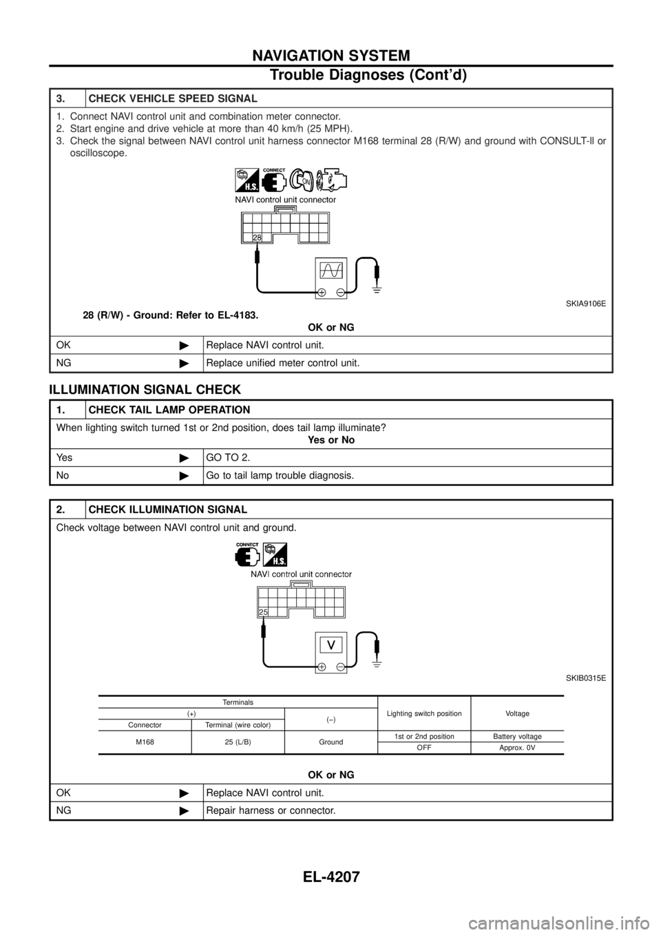
3. CHECK VEHICLE SPEED SIGNAL
1. Connect NAVI control unit and combination meter connector.
2. Start engine and drive vehicle at more than 40 km/h (25 MPH).
3. Check the signal between NAVI control unit harness connector M168 terminal 28 (R/W) and ground with CONSULT-ll oroscilloscope.
SKIA9106E
28 (R/W) - Ground: Refer to EL-4183. OK or NG
OK ©Replace NAVI control unit.
NG ©Replace uni®ed meter control unit.
ILLUMINATION SIGNAL CHECK
1. CHECK TAIL LAMP OPERATION
When lighting switch turned 1st or 2nd position, does tail lamp illuminate?
YesorNo
Ye s ©GO TO 2.
No ©Go to tail lamp trouble diagnosis.
2. CHECK ILLUMINATION SIGNAL
Check voltage between NAVI control unit and ground.
SKIB0315E
OK or NG
OK ©Replace NAVI control unit.
NG ©Repair harness or connector.
Terminals
Lighting switch position Voltage
(+)
(þ)
Connector Terminal (wire color)
M168 25 (L/B) Ground 1st or 2nd position Battery voltage
OFF Approx. 0V
NAVIGATION SYSTEM
Trouble Diagnoses (Cont'd)
EL-4207
Page 303 of 579
IGNITION SIGNAL CHECK
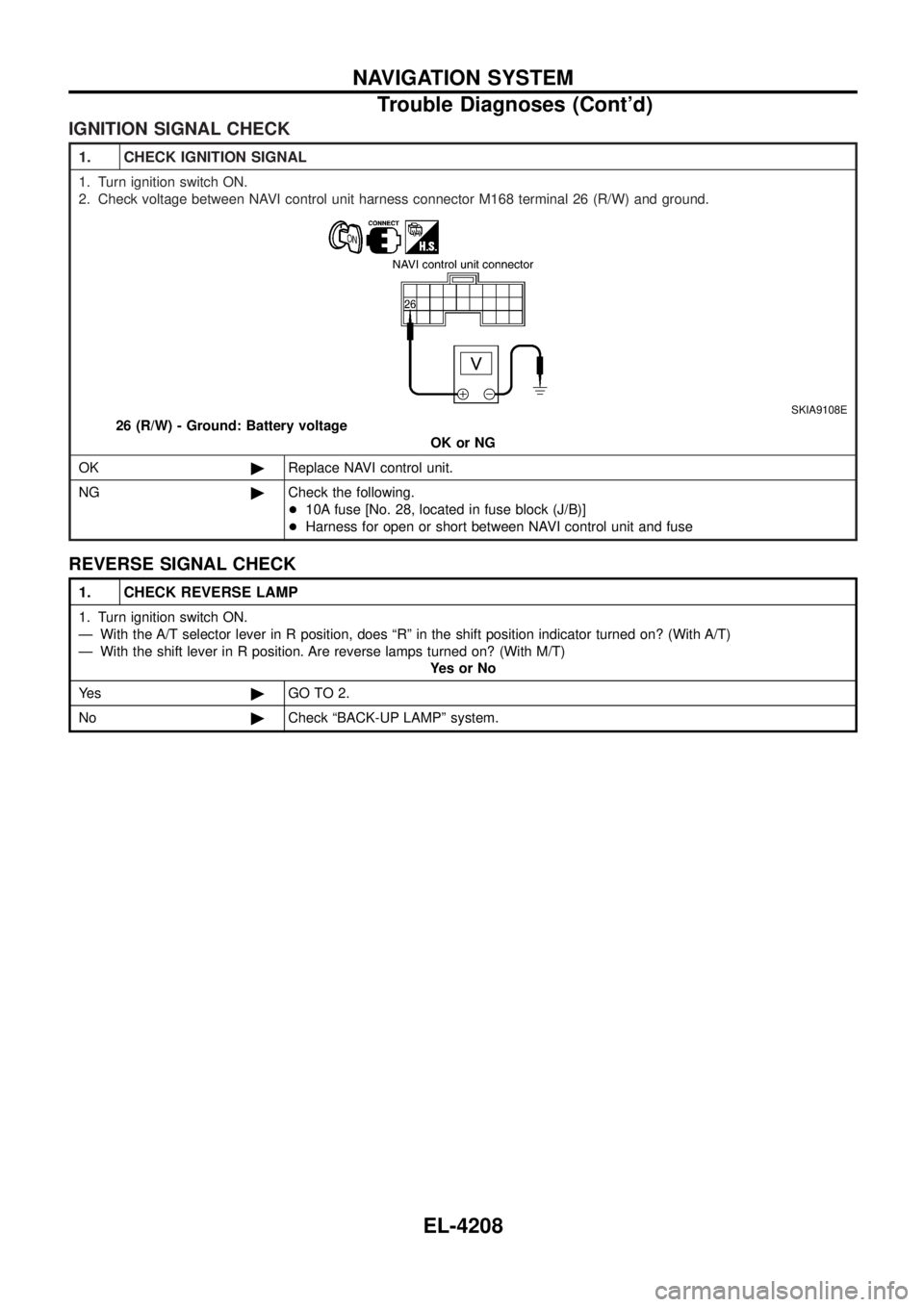
1. CHECK IGNITION SIGNAL
1. Turn ignition switch ON.
2. Check voltage between NAVI control unit harness connector M168 terminal 26 (R/W) and ground.
SKIA9108E
26 (R/W) - Ground: Battery voltageOK or NG
OK ©Replace NAVI control unit.
NG ©Check the following.
+10A fuse [No. 28, located in fuse block (J/B)]
+ Harness for open or short between NAVI control unit and fuse
REVERSE SIGNAL CHECK
1. CHECK REVERSE LAMP
1. Turn ignition switch ON.
Ð With the A/T selector lever in R position, does ªRº in the shift position indicator turned on? (With A/T)
Ð With the shift lever in R position. Are reverse lamps turned on? (With M/T)
YesorNo
Ye s ©GO TO 2.
No ©Check ªBACK-UP LAMPº system.
NAVIGATION SYSTEM
Trouble Diagnoses (Cont'd)
EL-4208
Page 304 of 579

2. CHECK REVERSE SIGNAL
+Shift the A/T selector lever in R position. (With A/T)
+ Shift the shift lever in R position. (With M/T)
Ð Check voltage between NAVI control unit and ground.
SKIA8728E
OK or NG
OK ©Replace NAVI control unit.
NG ©Check the following.
+Harness for open or short between NAVI control unit and park/neutral position switch
(A/T models)
+ Harness for open or short between NAVI control unit and back-up lamp switch (M/T
models)
Terminals
A/T selector lever position Voltage (V)
(+)
(þ)
Connector Terminal (wire color)
M168 27 (Y) Ground R position Battery voltage
Other than R position Approx. 0
COLOR OF RGB IMAGE IS NOT PROPER
1. CHECK COLOR BAR DIAGNOSIS
Check color tone by ªSCREEN ADJUSTMENTº of CONFIRMATION/ADJUSTMENT function. OK or NG
OK ©INSPECTION END
NG ©GO TO 2.
NAVIGATION SYSTEM
Trouble Diagnoses (Cont'd)
EL-4209
Page 442 of 579

Wiring Diagram Codes (Cell Codes)
Use the chart below to ®nd out what each wiring diagram code
stands for.
Refer to the wiring diagram code in the alphabetical index to ®nd
the location (Page number) of each wiring diagram.
Code Section Wiring Diagram Name
A/C, A HA Auto Air Conditioner
A/C, M HA Manual Air Conditioner
A/CCUT EC Air Conditioner Control
A/T AT A/T
ASCD EL Automatic Speed Control Device
AUDIO EL Audio
BACK/L EL Back-up Lamp
CD/CHG EL CD Auto Changer
CHIME EL Warning Chime
COMPAS EL Compass and Thermometer
COOL/B HA Cool Box
D/LOCK EL Power Door Lock
DEF EL Rear Window Defogger
DEICER EL Wiper Deicer
DTRL EL Headlamp Ð Daytime Light System
F/FOG EL Front Fog Lamp
FICD EC IACV-FICD Solenoid Valve
GLOW EC Quick Glow System
H/AIM EL Headlamp Aiming Control System
H/LAMP EL Headlamp
HEATUP EC Heat Up Switch
HLC EL Headlamp Washer
HORN EL Horn
HSEAT EL Heated Seat
ILL EL Illumination
LOAD EC Electrical Load Signal
MAFS EC Mass Air Flow Sensor
METER EL Meter and Gauges
MIRROR EL Door Mirror
MULTI EL Multi-remote Control System
NATS EL Nissan Anti-Theft System
NAVI EL Navigation System
NONDTC AT Non-detective Items
P/ANT EL Power Antenna
PHONE EL Telephone
POWER EL Power Supply Routing
R/COOL HA Rear Cooler System
R/FOG EL Rear Fog LampCode Section Wiring Diagram Name
R/HEAT HA Rear Heater System
REMOTE EL Audio (Remote Control Switch)
ROOM/L EL Interior Room Lamp
S/LOCK EL Power Door Lock Ð Super Lock
S/TANK FE Sub Fuel Tank Control System
SRS RS Supplemental Restraint System
STAB RA Stabilizer Release Device
STOP/L EL Stop Lamp
TAIL/L EL Parking, License and Tail Lamps
THEFT EL Theft Warning System
TRQ/SG EC Engine Torque Control Signal
TURN EL Turn Signal and Hazard Warning
Lamps
VSS EC Vehicle Speed Sensor
WARN EL Warning Lamps
WINDOW EL Power Window
WIP/R EL Rear Wiper and Washer
WIPER EL Front Wiper and Washer
WIRING DIAGRAM CODES (CELL CODES)
EL-4347
Page 457 of 579
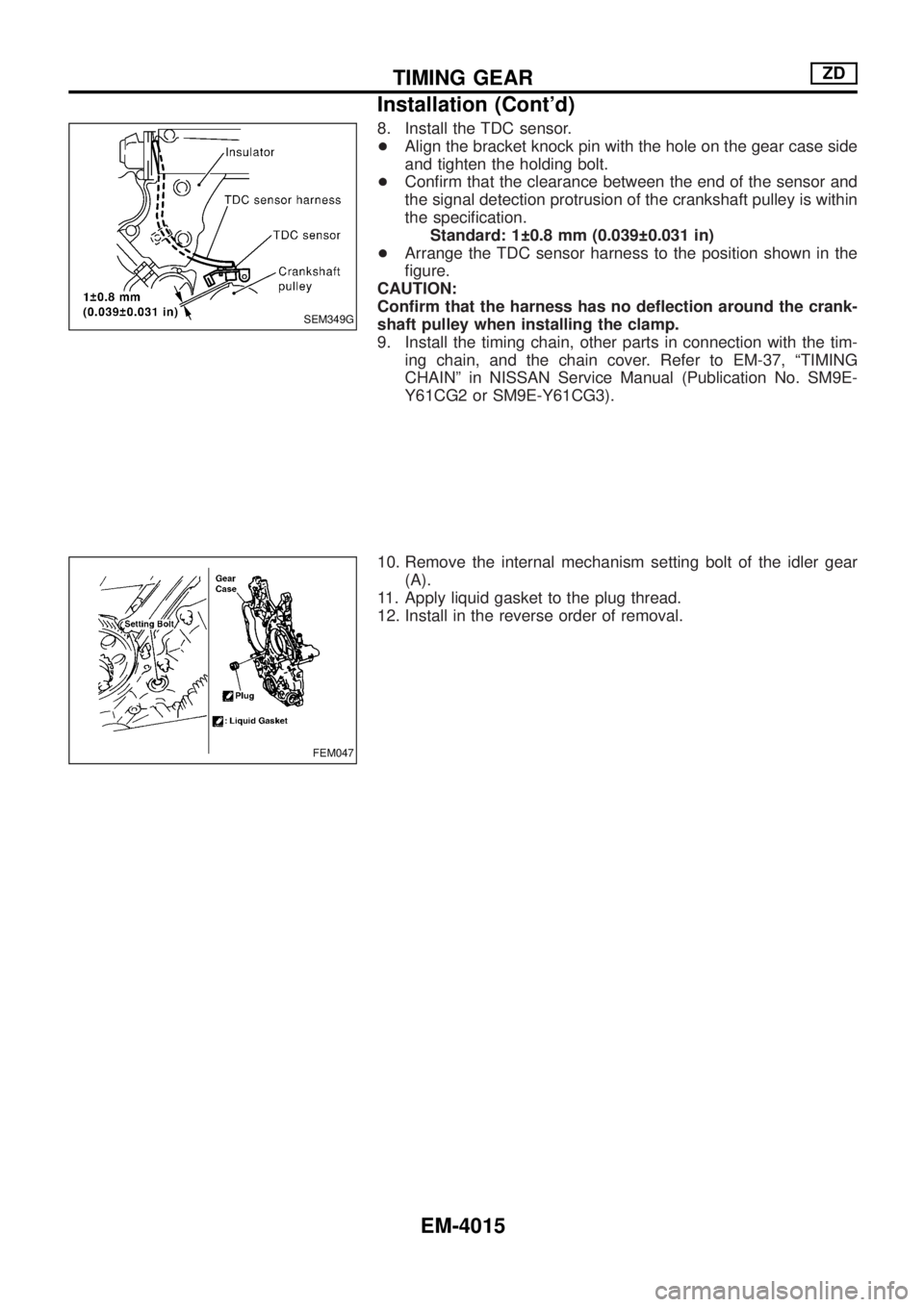
8. Install the TDC sensor.
+Align the bracket knock pin with the hole on the gear case side
and tighten the holding bolt.
+Con®rm that the clearance between the end of the sensor and
the signal detection protrusion of the crankshaft pulley is within
the speci®cation.
Standard: 1 0.8 mm (0.039 0.031 in)
+Arrange the TDC sensor harness to the position shown in the
®gure.
CAUTION:
Con®rm that the harness has no de¯ection around the crank-
shaft pulley when installing the clamp.
9. Install the timing chain, other parts in connection with the tim-
ing chain, and the chain cover. Refer to EM-37, ªTIMING
CHAINº in NISSAN Service Manual (Publication No. SM9E-
Y61CG2 or SM9E-Y61CG3).
10. Remove the internal mechanism setting bolt of the idler gear
(A).
11. Apply liquid gasket to the plug thread.
12. Install in the reverse order of removal.
SEM349G
FEM047
TIMING GEARZD
Installation (Cont'd)
EM-4015
Page 461 of 579
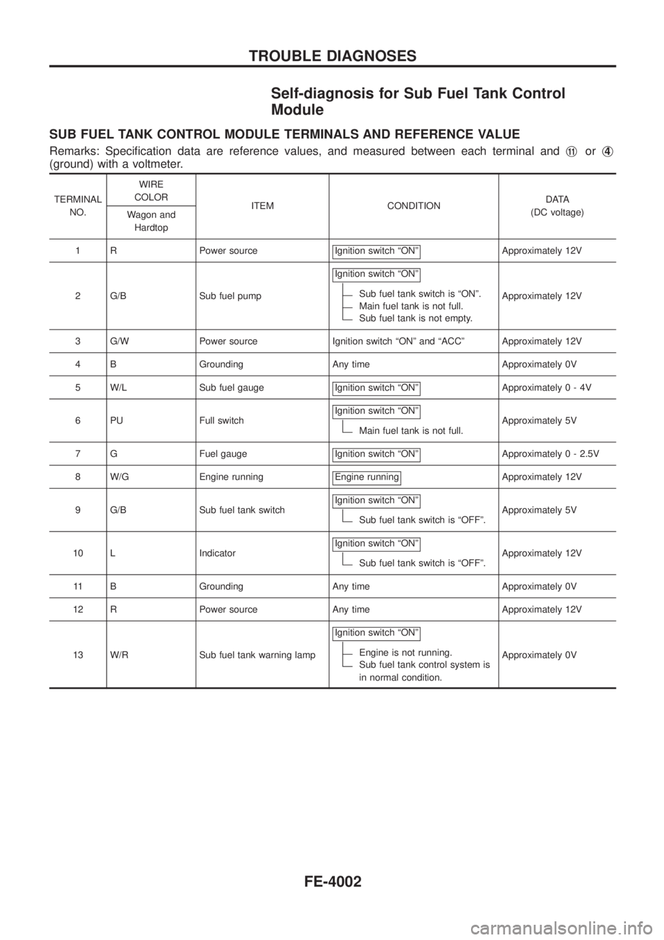
Self-diagnosis for Sub Fuel Tank Control
Module
SUB FUEL TANK CONTROL MODULE TERMINALS AND REFERENCE VALUE
Remarks: Speci®cation data are reference values, and measured between each terminal andj11orj4
(ground) with a voltmeter.
TERMINAL
NO.WIRE
COLOR
ITEM CONDITIONDATA
(DC voltage)
Wagon and
Hardtop
1 R Power source Ignition switch ªONº
Approximately 12V
2 G/B Sub fuel pumpIgnition switch ªONº
Sub fuel tank switch is ªONº.
Main fuel tank is not full.
Sub fuel tank is not empty.Approximately 12V
3 G/W Power source Ignition switch ªONº and ªACCº Approximately 12V
4 B Grounding Any time Approximately 0V
5 W/L Sub fuel gauge Ignition switch ªONº
Approximately0-4V
6 PU Full switchIgnition switch ªONº
Main fuel tank is not full.Approximately 5V
7 G Fuel gauge Ignition switch ªONº
Approximately 0 - 2.5V
8 W/G Engine running Engine running
Approximately 12V
9 G/B Sub fuel tank switchIgnition switch ªONº
Sub fuel tank switch is ªOFFº.Approximately 5V
10 L IndicatorIgnition switch ªONº
Sub fuel tank switch is ªOFFº.Approximately 12V
11 B Grounding Any time Approximately 0V
12 R Power source Any time Approximately 12V
13 W/R Sub fuel tank warning lampIgnition switch ªONº
Engine is not running.
Sub fuel tank control system is
in normal condition.Approximately 0V
TROUBLE DIAGNOSES
FE-4002
Page 547 of 579
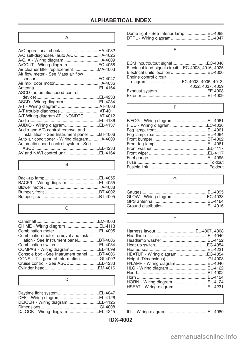
A
A/C operational check ................................HA-4032
A/C self-diagnoses (auto A/C)....................HA-4025
A/C, A - Wiring diagram .............................HA-4009
A/CCUT - Wiring diagram ..........................EC-4058
Air cleaner ®lter replacement .....................MA-4003
Air ¯ow meter - See Mass air ¯ow
sensor .....................................................EC-4047
Air mix. door motor.....................................HA-4036
Antenna .......................................................EL-4164
ASCD (automatic speed control
device) .....................................................EL-4233
ASCD - Wiring diagram ..............................EL-4234
A/T - Wiring diagram ...................................AT-4003
A/T trouble diagnoses .................................AT-4011
A/T Wiring diagram AT - NONDTC .............AT-4012
Audio ...........................................................EL-4136
AUDIO - Wiring diagram .............................EL-4137
Audio and A/C control removal and
installation - See Instrument panel .........BT-4006
Auto air conditioner - Wiring diagram ........HA-4009
Automatic speed control system - See
ASCD ......................................................EL-4233
AV and NAVI control unit ............................EL-4164
B
Back-up lamp ..............................................EL-4055
BACK/L - Wiring diagram............................EL-4055
Blower motor ..............................................HA-4038
Bumper, front ..............................................BT-4002
Bumper, rear ...............................................BT-4005
C
Camshaft ....................................................EM-4003
CHIME - Wiring diagram .............................EL-4113
Combination meter......................................EL-4095
Combination meter removal and instal-
lation - See Instrument panel..................BT-4006
Combination switch .....................................EL-4034
COMPAS - Wiring diagram .........................EL-4099
Console box - See Instrument panel ..........BT-4006
CONSULT-II general information.................GI-4002
Cruise control - See ASCD .........................EL-4233
Cylinder head .............................................EM-4016
D
Daytime light system...................................EL-4047
DEF - Wiring diagram .................................EL-4126
DEICER - Wiring diagram...........................EL-4125
Dimensions ..................................................GI-4008
D/LOCK - Wiring diagram ...........................EL-4245Dome light - See Interior lamp ...................EL-4088
DTRL - Wiring diagram ...............................EL-4047
E
ECM input/output signal .............................EC-4040
Electrical load signal circuit ...EC-4008, 4016, 4025
Electrical units location ...............................EL-4300
Engine control circuit
diagram .............................EC-4003, 4005, 4013,
4022, 4037, 4059
Exhaust system ..........................................FE-4008
Exterior ........................................................BT-4009
F
F/FOG - Wiring diagram .............................EL-4061
FICD - Wiring diagram ...............................EC-4036
Fog lamp, front............................................EL-4061
Fog lamp, rear ............................................EL-4064
Front bumper ..............................................BT-4002
Front fog lamp.............................................EL-4061
Front washer ...............................................EL-4117
Front wiper ..................................................EL-4117
Fuel gauge ..................................................EL-4095
Fuse ..............................................................Foldout
Fusible link....................................................Foldout
G
Gauges........................................................EL-4095
GLOW - Wiring diagram.............................EC-4033
GPS antenna ..............................................EL-4164
Ground distribution......................................EL-4016
H
Harness layout ..................................EL-4307, 4308
Headlamp ....................................................EL-4040
Headlamp washer .......................................EL-4122
Heat up switch............................................EC-4054
Heated seat.................................................EL-4231
HEATUP - Wiring diagram .........................EC-4054
Height (Dimensions) ....................................GI-4008
H/LAMP - Wiring diagram ...........................EL-4040
HLC - Wiring diagram .................................EL-4122
Hood............................................................BT-4002
Horn ............................................................EL-4124
HORN - Wiring diagram..............................EL-4124
HSEAT - Wiring diagram.............................EL-4231
I
ILL - Wiring diagram ...................................EL-4080
ALPHABETICAL INDEX
IDX-4002
Page 548 of 579
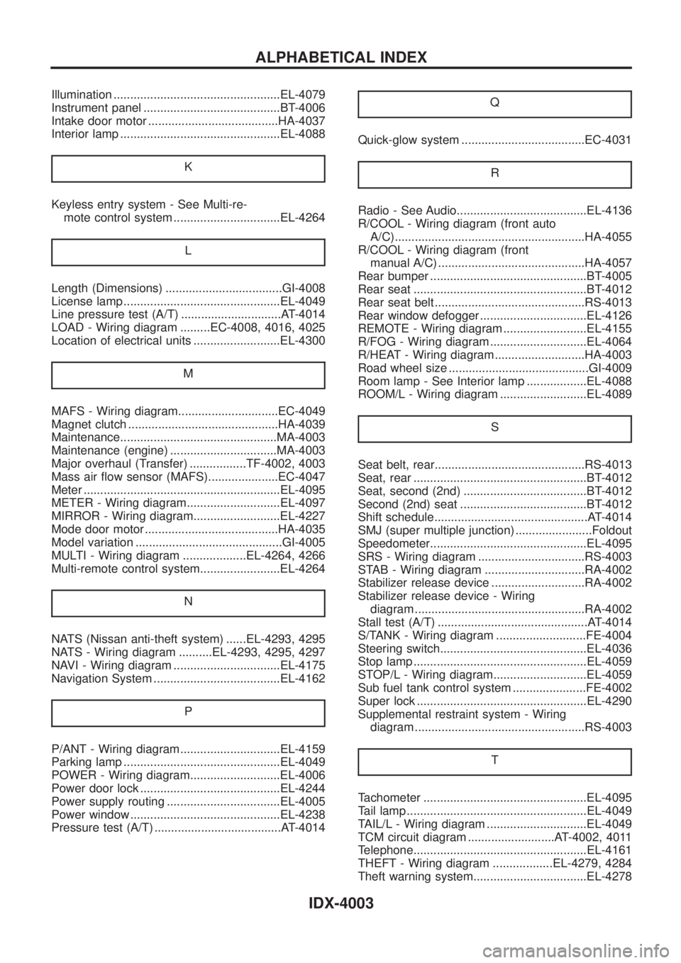
Illumination ..................................................EL-4079
Instrument panel .........................................BT-4006
Intake door motor .......................................HA-4037
Interior lamp ................................................EL-4088
K
Keyless entry system - See Multi-re-
mote control system ................................EL-4264
L
Length (Dimensions) ...................................GI-4008
License lamp ...............................................EL-4049
Line pressure test (A/T) ..............................AT-4014
LOAD - Wiring diagram .........EC-4008, 4016, 4025
Location of electrical units ..........................EL-4300
M
MAFS - Wiring diagram..............................EC-4049
Magnet clutch .............................................HA-4039
Maintenance...............................................MA-4003
Maintenance (engine) ................................MA-4003
Major overhaul (Transfer) .................TF-4002, 4003
Mass air ¯ow sensor (MAFS).....................EC-4047
Meter ...........................................................EL-4095
METER - Wiring diagram............................EL-4097
MIRROR - Wiring diagram..........................EL-4227
Mode door motor ........................................HA-4035
Model variation ............................................GI-4005
MULTI - Wiring diagram ...................EL-4264, 4266
Multi-remote control system........................EL-4264
N
NATS (Nissan anti-theft system) ......EL-4293, 4295
NATS - Wiring diagram ..........EL-4293, 4295, 4297
NAVI - Wiring diagram ................................EL-4175
Navigation System ......................................EL-4162
P
P/ANT - Wiring diagram..............................EL-4159
Parking lamp ...............................................EL-4049
POWER - Wiring diagram...........................EL-4006
Power door lock ..........................................EL-4244
Power supply routing ..................................EL-4005
Power window .............................................EL-4238
Pressure test (A/T) ......................................AT-4014Q
Quick-glow system .....................................EC-4031
R
Radio - See Audio.......................................EL-4136
R/COOL - Wiring diagram (front auto
A/C).........................................................HA-4055
R/COOL - Wiring diagram (front
manual A/C) ............................................HA-4057
Rear bumper ...............................................BT-4005
Rear seat ....................................................BT-4012
Rear seat belt .............................................RS-4013
Rear window defogger ................................EL-4126
REMOTE - Wiring diagram .........................EL-4155
R/FOG - Wiring diagram .............................EL-4064
R/HEAT - Wiring diagram ...........................HA-4003
Road wheel size ..........................................GI-4009
Room lamp - See Interior lamp ..................EL-4088
ROOM/L - Wiring diagram ..........................EL-4089
S
Seat belt, rear.............................................RS-4013
Seat, rear ....................................................BT-4012
Seat, second (2nd) .....................................BT-4012
Second (2nd) seat ......................................BT-4012
Shift schedule..............................................AT-4014
SMJ (super multiple junction) .......................Foldout
Speedometer...............................................EL-4095
SRS - Wiring diagram ................................RS-4003
STAB - Wiring diagram ..............................RA-4002
Stabilizer release device ............................RA-4002
Stabilizer release device - Wiring
diagram ...................................................RA-4002
Stall test (A/T) .............................................AT-4014
S/TANK - Wiring diagram ...........................FE-4004
Steering switch............................................EL-4036
Stop lamp ....................................................EL-4059
STOP/L - Wiring diagram............................EL-4059
Sub fuel tank control system ......................FE-4002
Super lock ...................................................EL-4290
Supplemental restraint system - Wiring
diagram ...................................................RS-4003
T
Tachometer .................................................EL-4095
Tail lamp ......................................................EL-4049
TAIL/L - Wiring diagram ..............................EL-4049
TCM circuit diagram ..........................AT-4002, 4011
Telephone....................................................EL-4161
THEFT - Wiring diagram ..................EL-4279, 4284
Theft warning system..................................EL-4278
ALPHABETICAL INDEX
IDX-4003
Page 549 of 579

Tire size .......................................................GI-4009
Tread-FR&RR (Dimensions)........................GI-4008
TRQ/SG - Wiring diagram................EC-4015, 4024
TURN - Wiring diagram ..............................EL-4068
Turn signal lamp .........................................EL-4067
U
UNIFIED METER CONTROL UNIT
(TIME CONTROL SYSTEM) ...................EL-4292
V
Valve clearance..........................................EM-4005
Valve lifter ..................................................EM-4003
Vehicle identi®cation number.......................GI-4007
Vehicle speed sensor (VSS) ...........EC-4004, 4007,
4053, 4060
Viscosity number (SAE) .............................MA-4002VSS - Wiring diagram ............EC-4004, 4053, 4060
W
WARN - Wiring diagram .............................EL-4102
Warning chime ............................................EL-4113
Warning lamps ............................................EL-4100
Washer, front ...............................................EL-4117
Water temperature gauge ...........................EL-4095
Wheel size ...................................................GI-4009
Wheelbase (Dimensions) ............................GI-4008
Width (Dimensions) .....................................GI-4008
WINDOW - Wiring diagram ........................EL-4239
WIP/R - Wiring diagram ..............................EL-4118
WIPER - Wiring diagram.............................EL-4117
Wiper deicer ................................................EL-4125
Wiper, front ..................................................EL-4117
Wiring Diagram (Cell code) list ...................EL-4347
ALPHABETICAL INDEX
IDX-4004
Page 552 of 579

Cleaning and Changing Air Cleaner Filter
+To properly tighten wing nuts, position clamps at four
places and tighten wing nuts until they touch air cleaner.
Then tighten them three more turns by hand.
CAUTION:
Do not use pliers or any other tools to tighten wing nuts.
+Clean inside air cleaner body when changing the element,
or cleaning for dry paper type.
SMA981C
ENGINE MAINTENANCETB45E, TB48DE
MA-4003